Embedded Programming
Group Assignment - Test the Toolchains and Workflows for Various Microcontrollers
For this assignment, my groupmates (Max Negrin, McKinnon Collins, and Oliver Abbot) and I worked with various microntrollers to create circuits and test their workflows. I worked with the Raspberry Pi Pico 2 W RP2350, and utilized the microcontroller to create a button LED circuit. You can find my documentation for this process on our group site
The Raspberry Pi Pico 2 is a compact microcontroller board built around the RP2350 chip, which provides dual-core processing, improved memory, and enhanced I/O capability. It is designed for embedded systems and prototyping, offering flexible GPIO and support for MicroPython or C/C++ to control electronic components and build efficient hardware projects.
Understanding the Pico 2 W
To develop an understanding of the microcontroller, I found the datasheet online, and consulted seller pages which summarized its features/specs. Using this information, I created the chart below.
| Feature | Raspberry Pi Pico 2W |
|---|---|
| Chip | RP2350A |
| CPU | Dual ARM Cortex-M33 (Armv8-M), or Dual RISC-V Hazard3 (RV32IMAC+) |
| CPU Clock | 48MHz, up to 150MHz |
| RAM Size | 520 KByte SRAM |
| Flash Size | 4 MByte Q-SPI Flash |
| Security | ARM TrustZone, 8KB OTP, Secure Boot |
| Wireless | IEEE 802.11 b/n/g (2.4GHz), Bluetooth 5.2 |
| Programming Language | MicroPython, CircuitPython, C, C++ |
| MCU Voltage | 3.3VDC |
| GPIO Voltage | 3.3VDC |
| GPIO | 26 x Digital Input/Output (Total) |
| PWM | 16 |
| Programmable IO | 3 x PIO v2 Blocks (12 PIO State Machines) |
| Debugging | ARM Serial Wire Debug (SWD) |
Setting up the Pico 2 W
To set up the Pico 2 W to work with MicroPython, I first downloaded the Pico 2 W UF2 firmware from the official micropython website (specifically from this page). Then, I put the microcontroller in BOOTSEL mode by holding the BOOTSEL button and then plugging it in. This opened a drive in my MacBook called RP2350. I then dragged the .uf2 file into the new drive. Once the drive disappeared, I could confirm that the Pico 2 W was successfully configured to run MicroPython.
To make working with MicroPython a lot easier, I installed the MicroPico VSCode extension (created by paulober). This extension allowed me to create and configure Python projects directly from the command palette, as well as freely load and run code onto my microcontoller. To create a new project, I first accessed the command palette by pressing Command + Shift + P, and then ran MicroPico: Create New Project. This generated a base file structure with all necessary MicroPython components.
Creating the Night Light Circuit
The idea for this circuit was heavily inspired by a list of ideas created by ChatGPT. The circuit itself and the corresponding code was based off of this video.
Here are the required components:
- x 1 Raspberry Pi Pico 2 W RP2350
- x 5 Male-to-Male Header Wires
- x 2 Female-to-Female Header Wires
- x 1 LDR Sensor Module
- x 1 LDR Photo Resistor
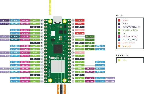
To start, I grasped an understanding of the circuit's wiring by consulting the Pico 2 W's pinout.
With this, I could then wire the circuit. I followed this wiring diagram/orientation to create my circuit.
| Component | Pin | Connects To (Pico 2 W) | Type | Purpose / Notes |
|---|---|---|---|---|
| LDR Module | VCC |
3V3 (OUT) |
Power | Supplies 3.3V to sensor |
| LDR Module | GND |
GND |
Ground | Common ground |
| LDR Module | AO |
GP26 (ADC0) |
Analog Input | Reads light level (0–3.3V) |
| LDR Module | DO (optional) |
Any GPIO (optional) | Digital Input | Threshold-based HIGH/LOW output |
| LED | Anode (long leg) | GP15 |
Digital Output | Controlled by GPIO |
| LED | Cathode (short leg) | GND |
Ground | Completes circuit |
| Resistor | — | Between GP15 and LED anode |
Current Limiting | Prevents LED damage |
| Power Rail (Breadboard) | + |
3V3 (OUT) |
Power Bus | Distributes 3.3V |
| Ground Rail (Breadboard) | – |
GND |
Ground Bus | Shared ground for all components |
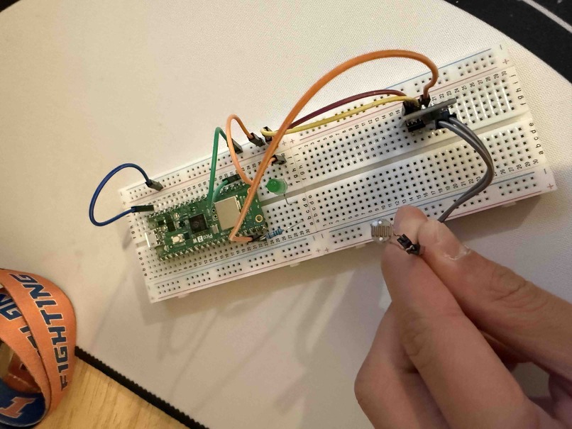
Once wired, I had a circuit that looked like this.
Coding the Circuit
To program this circuit, I asked ChatGPT to generate me code that would take photoresistor input to turn the LED on when dark, and off when it senses light. This translated into binary values (1, 0) for on and off which could then be used to power the LED. Here is the code that it gave me.
import machine
import utime

led = machine.Pin(15, machine.Pin.OUT)
ldr = machine.Pin(14, machine.Pin.PULL_DOWN)

while True:
    if ldr.value():
        led.value(1)
        print("on")
        utime.sleep_ms(500)
    else:
        led.value(0)
        print("off")
        utime.sleep_ms(1000)
In my circuit, this code maps directly to the night light behavior. GP15 is set as an output to drive the LED, and GP14 is used as the sensor input from the LDR module's digital pin. Inside the loop, the Pico continuously reads the sensor value and switches the LED on (1) or off (0) based on that signal, while the serial prints just help me confirm what state it is in. The short delays make the output easier to read while testing.
I then ran this code in my VSCode MicroPython project by accessing the command palette and running MicroPico: Upload project to Pico (ensuring that my circuit was connected before). Luckily, my code functioned on the first try. When covering the photoresistor with my hand, the LED turned on and the terminal output was on. When left uncovered, the LED remained off and the terminal output was off.
If the player does not load, open the video directly
Reflection
This week helped me better understand what embedded programming actually looks like in practice, especially when hardware and software need to work together in real time. Reading the Pico 2 W datasheet was more useful than I expected because it gave me a clearer picture of the board's capabilities, not just the basic pin labels. Looking through things like voltage levels, GPIO behavior, and available interfaces made the wiring decisions feel more intentional instead of just copying a diagram.
Building the night light circuit also helped me connect theory to physical behavior. Once I wired the LDR module and LED to the Pico, I could see exactly how sensor input gets translated into output control. That process made it much easier to understand what each pin was doing and why stable power and ground connections matter so much for reliable behavior.
On the programming side, working in MicroPython was a really good introduction to embedded code because the syntax is simple, but the results are immediate on hardware. The while True loop and pin reads/writes made the logic very clear, and testing with serial output (on/off) helped me confirm what the board was reading from the sensor.
The MicroPico extension was especially helpful throughout this process. Being able to create the project, upload code, and run everything from VSCode command palette commands made the workflow much smoother and removed a lot of setup friction. Overall, this week gave me a much stronger foundation in microcontroller workflow, from reading documentation and wiring a circuit to deploying and testing code on the board.