For this assignment I designed two triply periodic minimal surface structures in Fusion 360. These are shapes with complex, repeating internal geometry that would be impossible to produce with subtractive manufacturing — you can't reach the inside with a drill or mill — making them perfect candidates for 3D printing.
Both models were created using the same process: I started with a solid cube, then used Fusion 360's Volumetric Lattice tool to replace the solid body with a lattice pattern. The tool lets you pick from different surface types and adjust cell size and thickness.
How to Find the Volumetric Lattice Tool in Fusion 360
The Volumetric Lattice tool isn't in the most obvious place — here's where to find it and how to use it:

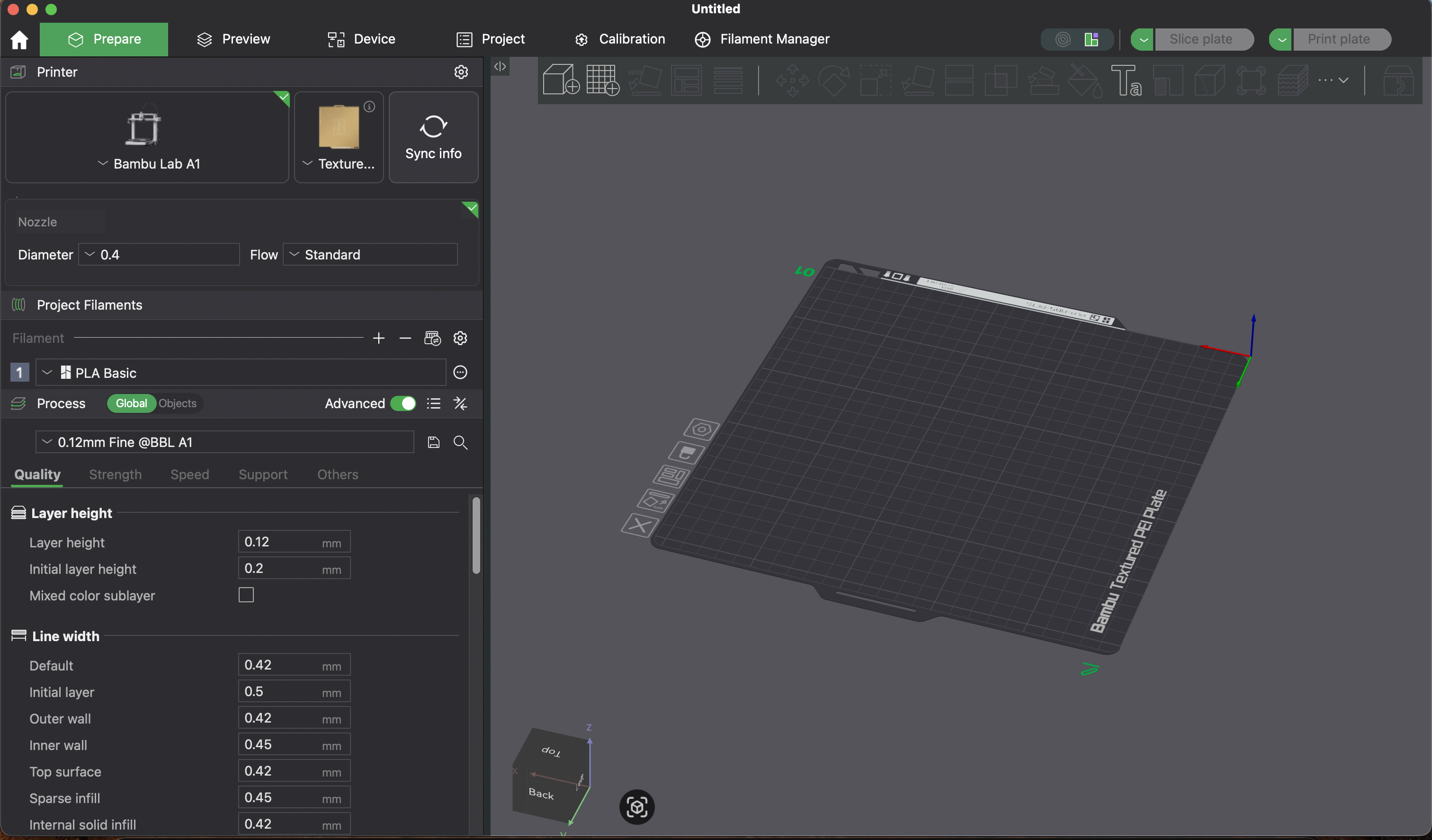
Where to find the Volumetric Lattice tool in Fusion 360 — it's under the Mesh workspace, not the standard Solid modeling workspace

Using the Volumetric Lattice tool — select your solid body, choose a surface type (Gyroid, Schwarz D, etc.), and adjust cell size and wall thickness
Volumetric Lattice Tool — Key Features
- Surface types: Gyroid, Schwarz D (Diamond), Schwarz P (Primitive), Neovius, and others — each produces a different repeating minimal surface geometry
- Cell size: Controls how large each repeating unit is. Smaller cells = more detail but harder to print; larger cells = easier to print but less structural density
- Wall thickness: How thick the lattice walls are. Thicker = stronger but heavier; thinner = lighter but more fragile
- Fill type: You can choose between surface-only (hollow walls) or solid fill (thickened walls)
- Important: After generating the lattice, you must convert it to a mesh (right-click → Convert to Mesh) before exporting as STL. If you skip this step, the slicer will just see a solid cube.
When I first tried to export the lattice to Bambu Studio for slicing, it just showed up as a solid cube — the slicer couldn't interpret the lattice data directly. After some troubleshooting, the solution I came up with was to convert the lattice structure to a mesh inside Fusion 360 before exporting the STL. That's why the models below look a bit faceted rather than perfectly smooth — the mesh conversion approximates the curved surfaces with flat triangles. Once 3D printed though, you won't be able to tell the difference at normal print resolution.
Gyroid Lattice Structure
The gyroid was discovered by NASA scientist Alan Schoen in 1970 while he was researching ultra-lightweight structures for space applications. It's a triply periodic minimal surface — meaning it repeats infinitely in all three directions and has zero mean curvature at every point (like a soap film). What makes it unique is that it has no straight lines and no planar symmetry — every surface curves smoothly in all directions.
Gyroids show up in nature too. Butterfly wings get some of their iridescent color from nanoscale gyroid structures, and certain types of sea urchin skeletons use the same geometry. In engineering, gyroids are used for lightweight structural parts because they distribute stress evenly across the entire surface, and their open-cell structure makes them useful for bone implants since tissue can grow through the channels.
I selected the Gyroid option in the Volumetric Lattice tool and adjusted the cell density to get a good balance between detail and printability.
Loading 3D model...
Gyroid lattice structure — designed in Fusion 360
Finished Gyroid Print
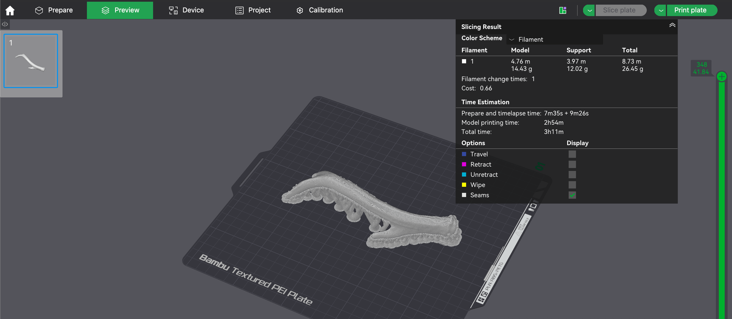
Bambu Studio — slicing the gyroid lattice for printing
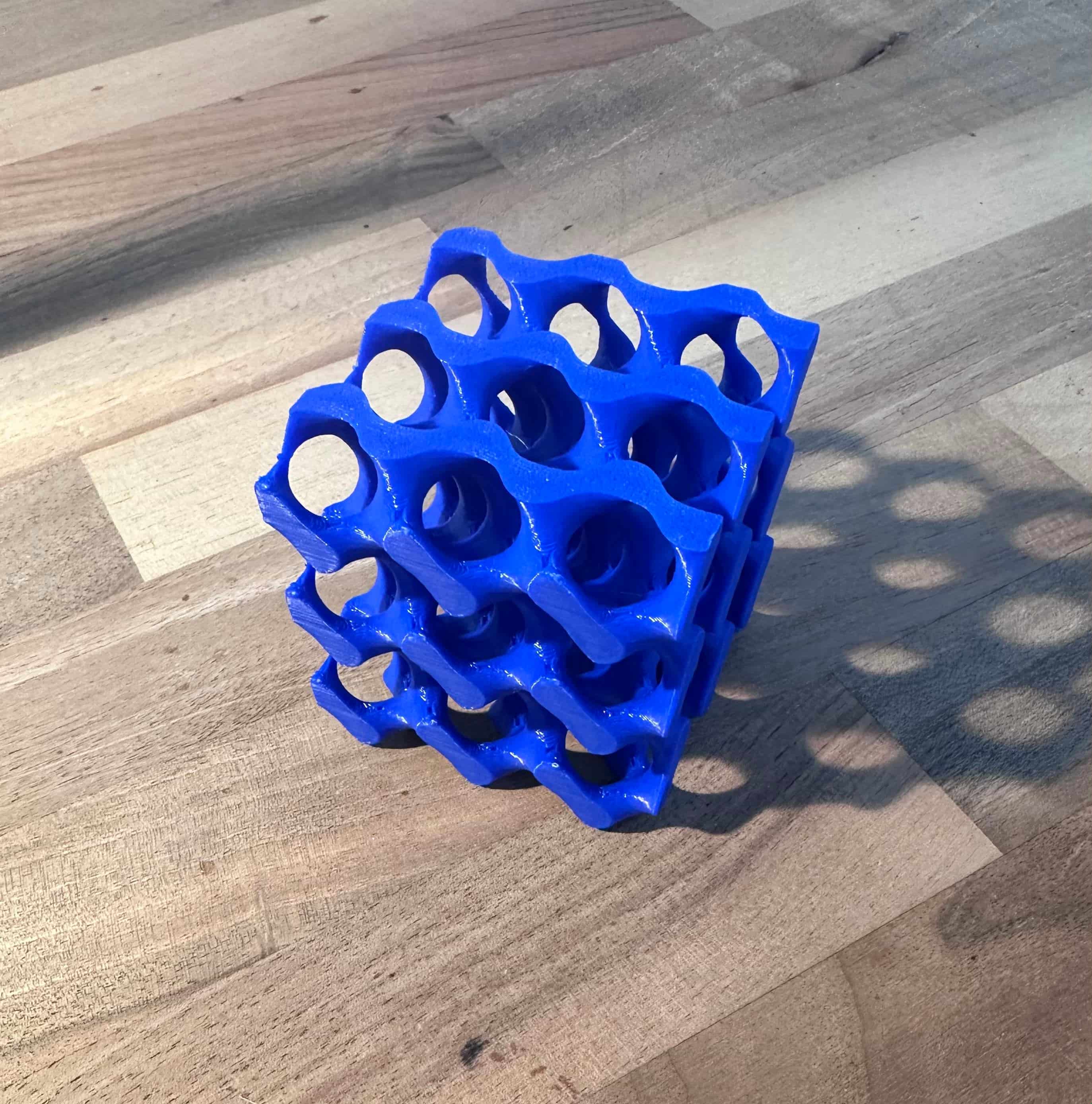
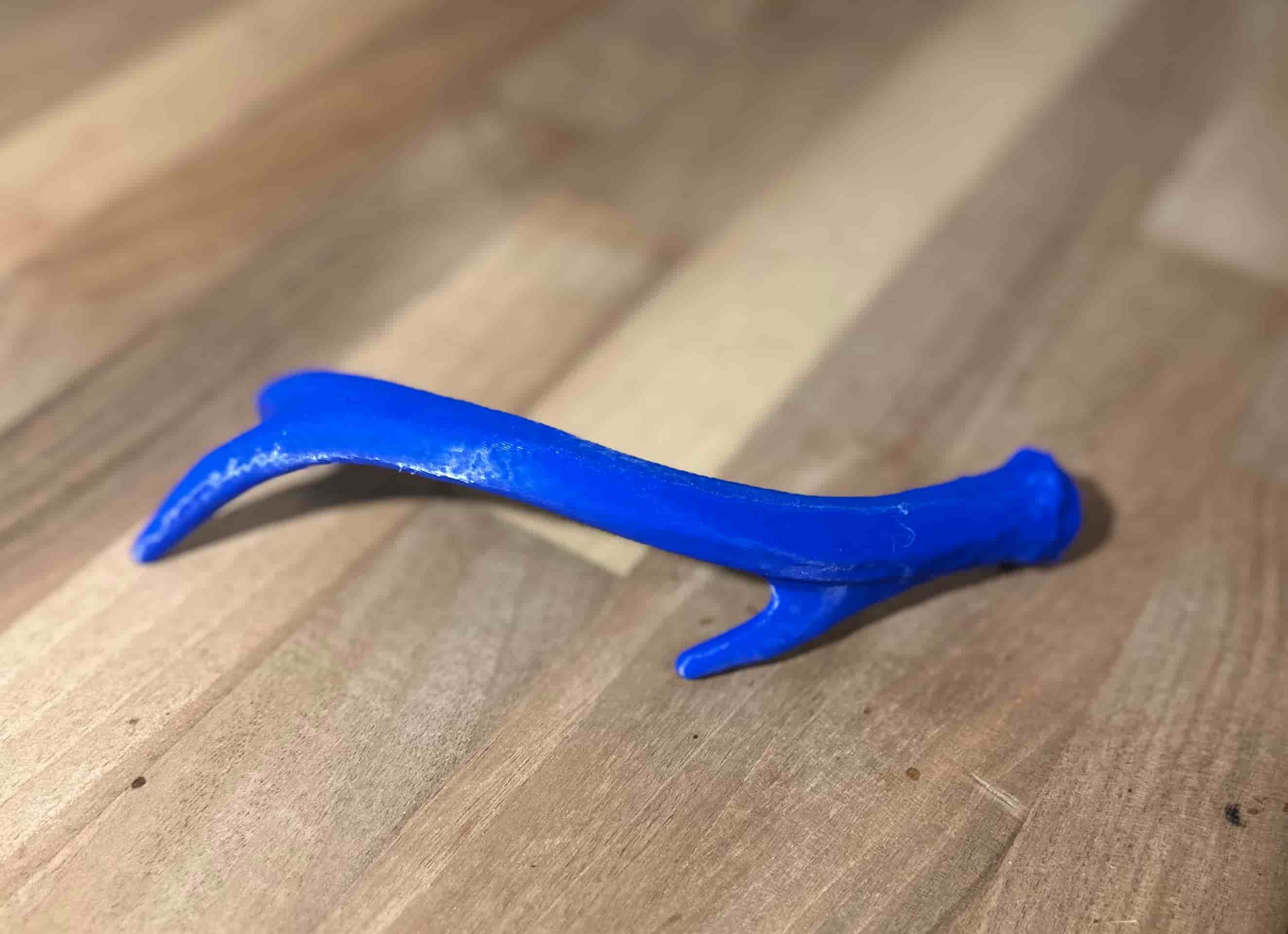
The finished gyroid lattice print — came out clean
Gyroid Print Settings & Troubleshooting
I printed the gyroid on a Bambu Lab A1 with Bambu Lab blue PLA Basic using the following settings:
- Infill pattern → Gyroid: Kind of funny — printing a gyroid with a gyroid infill pattern. But it actually makes sense: the gyroid infill follows similar curved paths as the model itself, which means the print head moves more smoothly and consistently rather than making sharp direction changes. This reduces vibration artifacts and gives better layer adhesion on the curved surfaces.
- Added thin tree supports: Tree supports branch out and only touch the model where needed, which means less scarring on the surface when you remove them. For a lattice structure with lots of small overhangs, tree supports reach into tight spots that normal block supports can't without filling the entire interior.
- Increased wall thickness: More walls means the outer shell of each lattice surface is thicker and stronger. On a model like this where the walls are the structure, adding wall thickness directly improves rigidity and reduces the chance of thin sections failing mid-print.
- Increased infill density to 30%: Higher infill gives the walls more internal support to bond to, which helps bridge the gaps between lattice surfaces. At lower densities, the thin curved sections don't have enough backing material and can warp or collapse during printing.
- Slow down by height: The printer automatically reduces speed on smaller layers near the top of the model, giving them more time to cool and solidify.
All other settings were left at the Bambu Studio slicer defaults.
Schwarz D (Diamond) Structure
The Schwarz Diamond surface was first described by German mathematician Hermann Schwarz in 1890, making it one of the oldest known triply periodic minimal surfaces. Schwarz was a student of Karl Weierstrass, and his work on minimal surfaces laid the groundwork for an entire branch of differential geometry. The "D" stands for Diamond because when you look at the surface's topology, it follows the same connectivity pattern as the carbon atoms in a diamond crystal lattice.
Compared to the gyroid, the diamond structure has sharper transitions and more defined channels running through it. This makes it particularly interesting for applications like heat exchangers (the channels allow fluid to flow through efficiently) and acoustic panels (the geometry scatters sound waves). It's also been studied for use in battery electrodes because the two interlocking channel networks can hold different materials while maximizing the surface area between them.
I used the same cube and Volumetric Lattice workflow, but selected the Schwarz Diamond option instead.
Loading 3D model...
Schwarz D (Diamond) structure — designed in Fusion 360
Finished Schwarz D Print
StructurePrintComp.jpg)
The finished Schwarz D diamond print — came out clean
Schwarz D Print Settings
I printed on a Bambu Lab A1 Mini with Bambu Lab white PLA Basic using the following settings:
- Infill pattern → Gyroid at 30% density: Gyroid infill prints faster than hexagonal because the nozzle moves in smooth continuous curves rather than making sharp direction changes at each corner. The 30% density gives the thin lattice walls enough internal support to bond to, which helps bridge the gaps between surfaces. At lower densities, the curved sections don't have enough backing material and can warp or collapse during printing.
- Increased wall loops: Adding more wall loops makes the printed walls thicker, which strengthens the model and reduces the chance of thin sections breaking mid-print. It also hides the internal infill pattern from being visible through the surface.
- Tree supports: Tree supports branch out from a central trunk and only touch the model where needed. They use less material than standard block supports, are easier to remove, and leave less scarring on the surface. For a lattice structure with lots of small overhangs, tree supports reach into tight spots that normal block supports can't without filling the entire interior.
- Slow down by height: This setting automatically reduces print speed as the model gets taller. As the lattice narrows toward the top, each layer has less area and less time to cool before the next layer goes down. Slowing down gives each layer more time to solidify, preventing heat buildup that can cause warping or blobbing on small cross-sections.
All other settings were left at the Bambu Studio slicer defaults.