Embedded Programming

This week focuses on programming microcontrollers and embedded systems, interacting with local input/output devices, and communicating with remote wired or wireless connections.

Assignment Requirements

Individual Assignment:

Project Documentation

Browsing the ATmega328P Datasheet

The Arduino Uno R3 is built around the ATmega328P microcontroller from Microchip (formerly Atmel). Here are the key specs I found while browsing the datasheet:

  • Architecture: 8-bit AVR RISC
  • Clock Speed: 16 MHz (external crystal on the Uno)
  • Flash Memory: 32 KB (0.5 KB used by bootloader)
  • SRAM: 2 KB
  • EEPROM: 1 KB
  • Digital I/O Pins: 14 (6 provide PWM output)
  • Analog Input Pins: 6 (10-bit ADC, 0–1023 range)
  • Operating Voltage: 5V
  • Communication: UART (Serial), SPI, I2C (TWI)
  • Built-in LED: Pin 13
  • USB Interface: ATmega16U2 handles USB-to-serial conversion

Compared to the ESP32-C6, the Uno is simpler — no WiFi or Bluetooth built in. But it runs at 5V logic, which makes it easier to interface with many sensors and modules directly without level shifting.

The Program — Button-Controlled LED

This program uses a pushbutton as local input and an LED as local output on the Arduino Uno R3. Each press of the button toggles the LED on or off using a simple state counter. The Arduino communicates with the computer over USB (UART serial) for uploading the code, satisfying the wired communication requirement.

Wiring

  • LED: Pin 8 → 220Ω resistor → LED anode (+) → LED cathode (−) → GND
  • Button: Pin 7 → one leg of button, other leg → 5V (with pull-down resistor to GND)
  • USB cable: Connected to computer for uploading code (wired serial communication)

Arduino Code

// Arduino Uno R3 — Button Toggle LED
// Local I/O: pushbutton (input on pin 7) + LED (output on pin 8)
// Wired communication: USB serial for code upload

unsigned const LED = 8;
unsigned const BUTTON = 7;
unsigned int bState = 0;

void setup() {
  pinMode(BUTTON, INPUT);
  pinMode(LED, OUTPUT);
}

void loop() {
  if (digitalRead(BUTTON) == 1) {
    digitalWrite(LED, HIGH);
    bState += 1;
    if (bState % 2 == 0) {
      digitalWrite(LED, LOW);
      bState = 0;
    }
    delay(100);
  }
}

How It Works

  • LED (pin 8): Configured as OUTPUT — this is the local output device.
  • Button (pin 7): Configured as INPUT — this is the local input device. When pressed, digitalRead returns 1 (HIGH).
  • Toggle logic: Each button press increments bState. On the first press (bState = 1, odd), the LED turns on. On the second press (bState = 2, even), the LED turns off and the counter resets to 0.
  • Delay: The 100ms delay acts as a simple debounce to prevent multiple triggers from a single press.
  • Wired communication: The program is uploaded to the Arduino over USB, which uses the ATmega16U2 chip for USB-to-UART serial conversion.

Tinkercad Circuit

Before building the physical circuit, I prototyped it in Tinkercad to verify the wiring and test the code in simulation:

Tinkercad circuit simulation of Arduino Uno with LED and pushbutton

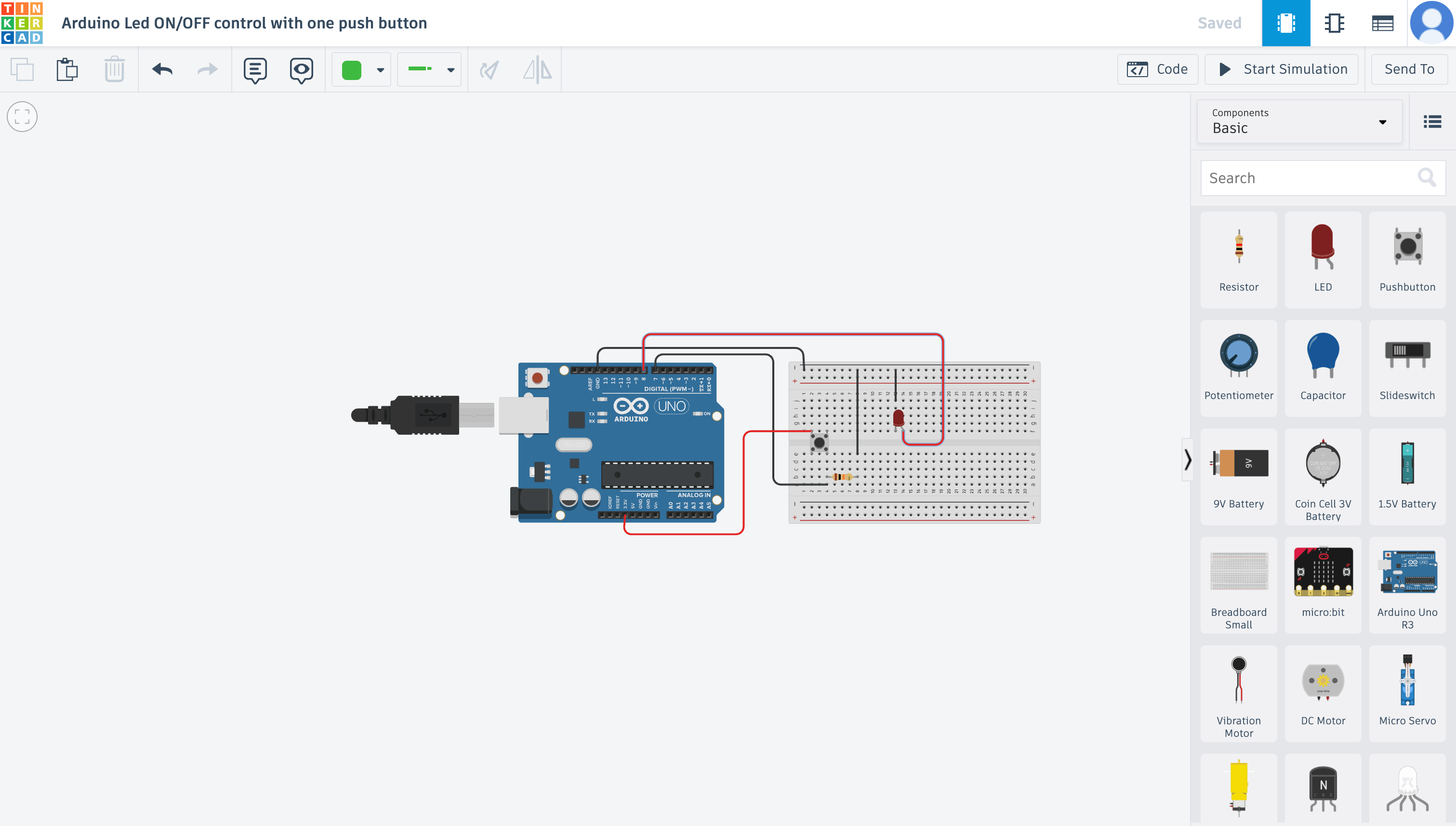
Tinkercad circuit simulation — Arduino Uno R3 with LED on pin 8 and pushbutton on pin 7

🔗 View Tinkercad Circuit

Video — Working Demo

Here's the circuit running on the real Arduino Uno R3. Each button press toggles the LED on or off — you can see the state change immediately after each press, with the 100ms delay preventing accidental double-triggers.

Arduino Uno R3 — pushbutton toggling the LED on and off

This demonstrates local interaction with both an input device (pushbutton) and an output device (LED), with the code uploaded via wired USB serial communication.

The XIAO ESP32-C6 is a compact, powerful microcontroller from Seeed Studio. Here are the key specs I found while browsing the datasheet:

  • Dual-core RISC-V processor
  • WiFi 6 (802.11ax) support
  • Bluetooth 5.3 (BLE)
  • Thread, Zigbee, and Matter protocol support
  • Built-in orange LED on GPIO 15
  • USB-C connector
  • No additional drivers required on Mac or Windows

The built-in LED on GPIO 15 is active-low, which means LOW turns it ON and HIGH turns it OFF. This tripped me up at first, so it's worth remembering.

Arduino IDE 2 is the simplest way to get started. It handles editing, compiling, and uploading all in one application.

Step 1 — Install Arduino IDE 2

Download the installer from arduino.cc/en/software. Run the installer and allow USB driver installation when prompted. No terminal commands needed.

Step 2 — Install the ESP32 Board Package

The IDE needs to know how to compile code for ESP32 boards:

  1. Go to File → Preferences
  2. Paste this URL into "Additional boards manager URLs":
    https://raw.githubusercontent.com/espressif/arduino-esp32/gh-pages/package_esp32_index.json
  3. Open Board Manager and search for "esp32"
  4. Install "esp32 by Espressif Systems"

⚠️ The download is 200+ MB, so be patient and keep a stable connection.

Step 3 — Select Board and Port

  1. Plug in the XIAO ESP32-C6 — the power LED should turn on
  2. Click "Select Board and Port" in the IDE
  3. Choose XIAO_ESP32C6 from the list
  4. Select the correct serial port (e.g., COM3 on Windows, /dev/cu.usbmodem14101 on Mac)

If no port appears, your cable is likely charge-only. This is the most common beginner mistake — make sure you're using a data-capable USB-C cable.

Step 4 — Upload a Blink Sketch

A "sketch" is an Arduino program with two required functions: setup() runs once, and loop() runs forever.

const int ledPin = 15;  // Built-in LED

void setup() {
  pinMode(ledPin, OUTPUT);
  Serial.begin(115200);
  Serial.println("ESP32-C6 Blink!");
}

void loop() {
  digitalWrite(ledPin, LOW);   // LED ON (active-low)
  delay(300);
  digitalWrite(ledPin, HIGH);  // LED OFF
  delay(300);
}

Click Upload (or press Ctrl/Cmd + U) and watch the LED blink. If it does, your environment is fully working.

Understanding the Code

  • const int ledPin = 15; — stores the LED pin number
  • pinMode(..., OUTPUT); — configures the pin to control the LED
  • Serial.begin(115200); — starts serial communication with the computer
  • digitalWrite(LOW); — turns LED ON (active-low wiring)
  • delay(300); — pauses the program for 0.3 seconds

Serial Monitor & Plotter

The Serial Monitor displays text messages from the board. If the text looks scrambled, the baud rate probably doesn't match your code (should be 115200).

The Serial Plotter graphs numeric data in real time. Send consistent numeric values and add small delays (10–100ms) for clean graphs. Note: Serial Monitor and Plotter cannot run at the same time.

Installing Libraries

Libraries provide pre-written code for sensors, displays, WiFi, and more:

  1. Open Library Manager
  2. Search for the library you need
  3. Click Install and choose "Install All" for dependencies
  4. Include it in your sketch: #include <LibraryName.h>

Check File → Examples after installing to see usage examples.

My Blink Test

To verify everything was working, I selected verbose output in the Arduino IDE upload settings. This let me see every step during compile and upload, which made it easy to confirm things were going through correctly.

Verbose output selection in Arduino IDE

Selecting verbose output in the Arduino IDE preferences

I uploaded a simple blink sketch to the board. To make sure it was actually running my code and not something pre-loaded, I changed the blink speed. When the LED matched my new timing, I knew the upload was successful.

#define LED_PIN 15   // built-in LED on XIAO ESP32-C6

void setup() {
  pinMode(LED_PIN, OUTPUT);
}

void loop() {
  digitalWrite(LED_PIN, HIGH);
  delay(100);
  digitalWrite(LED_PIN, LOW);
  delay(100);
}
XIAO ESP32-C6 board connected

XIAO ESP32-C6 board connected and running my blink code

The LED blinked at 100ms on/off — exactly what I set. This confirmed the board was receiving and running my code, and my development environment was fully working.

Blink Videos

I tested two different blink speeds to confirm the board was running my code and not something pre-loaded:

Fast blink

Slow blink

Changing the delay and seeing the LED match the new timing confirmed the upload was successful and my code was actually running on the board.

Helpful Keyboard Shortcuts

  • Compile: Ctrl/Cmd + R
  • Upload: Ctrl/Cmd + U
  • Serial Monitor: Ctrl/Cmd + Shift + M
  • Library Manager: Ctrl/Cmd + Shift + I

For a more structured workflow, you can use the Arduino CLI paired with VS Code. This gives you more control and a one-click build-and-upload process through VS Code tasks.

Step 1 — Install Arduino CLI

On Mac, install via Homebrew:

brew install arduino-cli
arduino-cli version

Step 2 — Configure the CLI

arduino-cli config init
arduino-cli config add board_manager.additional_urls https://raw.githubusercontent.com/espressif/arduino-esp32/gh-pages/package_esp32_index.json
arduino-cli core update-index
arduino-cli core install esp32:esp32

This installs everything needed to compile and upload code for ESP32 boards.

Step 3 — Set Up VS Code Tasks

Create a .vscode/tasks.json file in your project folder. This lets you compile and upload with a single click instead of typing commands every time. Use arduino-cli board list to find your board's port.

Step 4 — Project Organization

Recommended workflow:

  1. Create a template folder with your .ino file and .vscode config
  2. Copy it for each new project
  3. Rename the folder and .ino file so they match (Arduino requires this)
  4. Use Run Task → Build & Upload to deploy

Blink Test

Upload the same blink code to confirm your CLI setup works. If the LED blinks, you're good to go.

MicroPython is an alternative to Arduino for programming microcontrollers. This guide covers setting it up on RP2040-based boards like the Raspberry Pi Pico or Seeed XIAO RP2040.

What You Need

  • RP2040 microcontroller (Pico or XIAO RP2040)
  • Data-capable USB cable
  • Computer with internet
  • VS Code (recommended)

Step 1 — Install MicroPython Firmware

  1. Download the latest .uf2 firmware from the official MicroPython website
  2. Put your board into BOOT mode:
    • Raspberry Pi Pico: Hold the BOOTSEL button while plugging in USB
    • XIAO RP2040: Hold the small "B" button while connecting USB-C
  3. Your computer will detect a drive named RPI-RP2
  4. Drag and drop the .uf2 file onto the drive
  5. The board automatically reboots with MicroPython installed

✅ Success sign: The RPI-RP2 drive disappears after copying.

Step 2 — Install Python & mpremote

Make sure Python 3 is installed on your computer. On Mac, verify with:

python3 --version

Then install mpremote, which lets your computer send files directly to the microcontroller:

python3 -m pip install mpremote

Step 3 — Configure VS Code

  1. Install VS Code and the Python extension
  2. Create a project folder for your MicroPython files
  3. Create a .vscode/tasks.json that runs:
    mpremote connect auto fs cp main.py : + reset

This connects to the board, copies your main.py, and resets it so the code runs immediately — a one-click upload workflow.

Step 4 — Blink Test

Create a file named main.py using the onboard LED on Pin 25. Upload using Terminal → Run Task → Upload.

⚠️ Do NOT press the Play button in VS Code — that runs the script on your computer instead of the microcontroller.

How to Know It Worked

If the LED blinks, it means:

  • ✅ Firmware installed correctly
  • ✅ Computer communicates with the board
  • ✅ File upload works
  • ✅ Your development environment is ready

Common MicroPython Mistakes

  • "No module named machine" — You clicked Play instead of uploading. Use Run Task.
  • Board still shows "RPI-RP2" — It's still in bootloader mode. Unplug and reconnect without holding the boot button.
  • Permission errors (Mac) — Enable Input Monitoring in System Settings or reinstall mpremote.

Troubleshooting is a structured process — not guessing. Start simple, read error messages carefully, and change only one thing at a time so you know what fixed the issue.

The Master Flow

Always start with a Blink sketch and work through these checkpoints:

  1. Does the code compile?
  2. Does it upload?
  3. Does the LED blink?

If all three succeed, your system works. Many boards ship with a blink program pre-installed, so change the delay time to confirm your upload actually worked.

Code Won't Compile

Check in this order:

  1. Board selection — Make sure XIAO_ESP32C6 is selected
  2. ESP32 package — Install it through Board Manager if missing
  3. Syntax errors — Look for missing semicolons, brackets, or typos. The IDE highlights the problem line in red

Common compile errors:

Error Message Cause & Fix
"expected ';' before '}' Add the missing semicolon
'ledPin' was not declared Check spelling and declaration order
No such file or directory A library is missing — install via Library Manager
exit status 1 Scroll UP — the real error is above this message
Board not found / FQBN error Install the ESP32 package and reselect the board

Upload Fails

90% of upload failures come from three things:

  • Wrong cable (charge-only, no data)
  • Wrong port selected
  • Serial Monitor holding the port open

Boot Mode Rescue: If nothing else works, force programming mode: Hold BOOT → press RESET → release BOOT → then Upload.

LED Doesn't Blink After Upload

  • Confirm you're using GPIO 15
  • Remember the LED is active-low — LOW = ON, HIGH = OFF
  • Change delay(200) to delay(1000) — if the speed changes, your code is running

Serial Monitor Issues

  • Garbled text: Baud rate mismatch — match the monitor to your Serial.begin() value
  • Blank output: Check that Serial.begin() exists in your code, correct port is selected, and try pressing RESET
  • Can't open monitor: Port is busy — close Serial Plotter or other programs using the port

WiFi Connection Problems

  1. SSID must be spelled exactly (case-sensitive)
  2. Password must be correct
  3. Network must be 2.4 GHz — ESP32 cannot connect to 5 GHz-only networks
  4. School/corporate networks may block IoT devices

Power & Hardware Issues

  • Board won't power on: Try another cable, another USB port, or check for physical damage
  • Random resets: Usually a power issue or infinite loops in code
  • Flaky wiring: Push wires firmly, use shorter jumpers, check breadboard rails

When in doubt — go back to Blink. If Blink works, the problem is in your project code.

Quick Reference Table

Problem Likely Cause Fix
Won't compileWrong board / missing packageInstall ESP32 package
Syntax errorTypo or missing symbolFix highlighted line
Won't uploadWrong cable or portTry another cable
LED not blinkingHIGH/LOW reversedUse LOW for ON
Garbled serialBaud mismatchMatch baud rate
WiFi failsWrong credentials or 5GHzUse 2.4GHz network
Random resetsPower issueUse powered USB port

When to Ask for Help

Before asking, prepare:

  1. What you're trying to do
  2. The exact error message
  3. What you already tried

Try explaining the problem out loud first — it's called rubber duck debugging and it works surprisingly well.

For the week 4 group assignment, our team explored embedded programming across different microcontrollers. You can view the full group page here: Week 4 Group Assignment.

My Contributions

My portion of the group work focused on the Arduino Uno R3. I browsed the ATmega328P datasheet, documented the key specs, and programmed a button-controlled LED toggle circuit. I go into much deeper analysis of the Arduino Uno on my personal site in the Arduino Uno section.

I also helped troubleshoot problems that other students faced with the coding of the group site page.

Key Takeaways

Useful Links