This week focuses on laser cutting and vinyl cutting techniques for precise material processing and digital fabrication.
Assignment Requirements
Individual Assignments:
Design, lasercut, and document a parametric construction kit, accounting for the lasercutter kerf
Cut something on the vinyl cutter
Project Overview
From our group work/research, we found the kerf on the laser cutter to be 0.01 inch. This measurement is critical for designing parts that fit together properly, as the laser removes material equal to the kerf width when cutting.
My Group Work Contributions
For the group assignment, I wrote the Terms and Definitions section, covering the key laser cutting vocabulary: Focus/Focal Point, Power, Speed, Kerf, and Joint Clearance/Types. Each term includes a detailed explanation of what it means and why it matters for laser cutting. You can see my contributions on the group assignment page.
How I Compensated for Kerf
To account for the 0.01 inch kerf in my parametric construction kit, I adjusted all slot widths by adding 0.01 inch to ensure proper fit. For example, if the cardboard thickness was 3.53mm, I designed the slots to be 3.53mm + 0.01 inch to compensate for the material removed during cutting.
Why Kerf Matters
The laser beam has a physical width that removes material
Without compensation, parts will be too loose or won't fit
Parametric design allows easy adjustment for different materials
Testing is essential to verify the kerf measurement
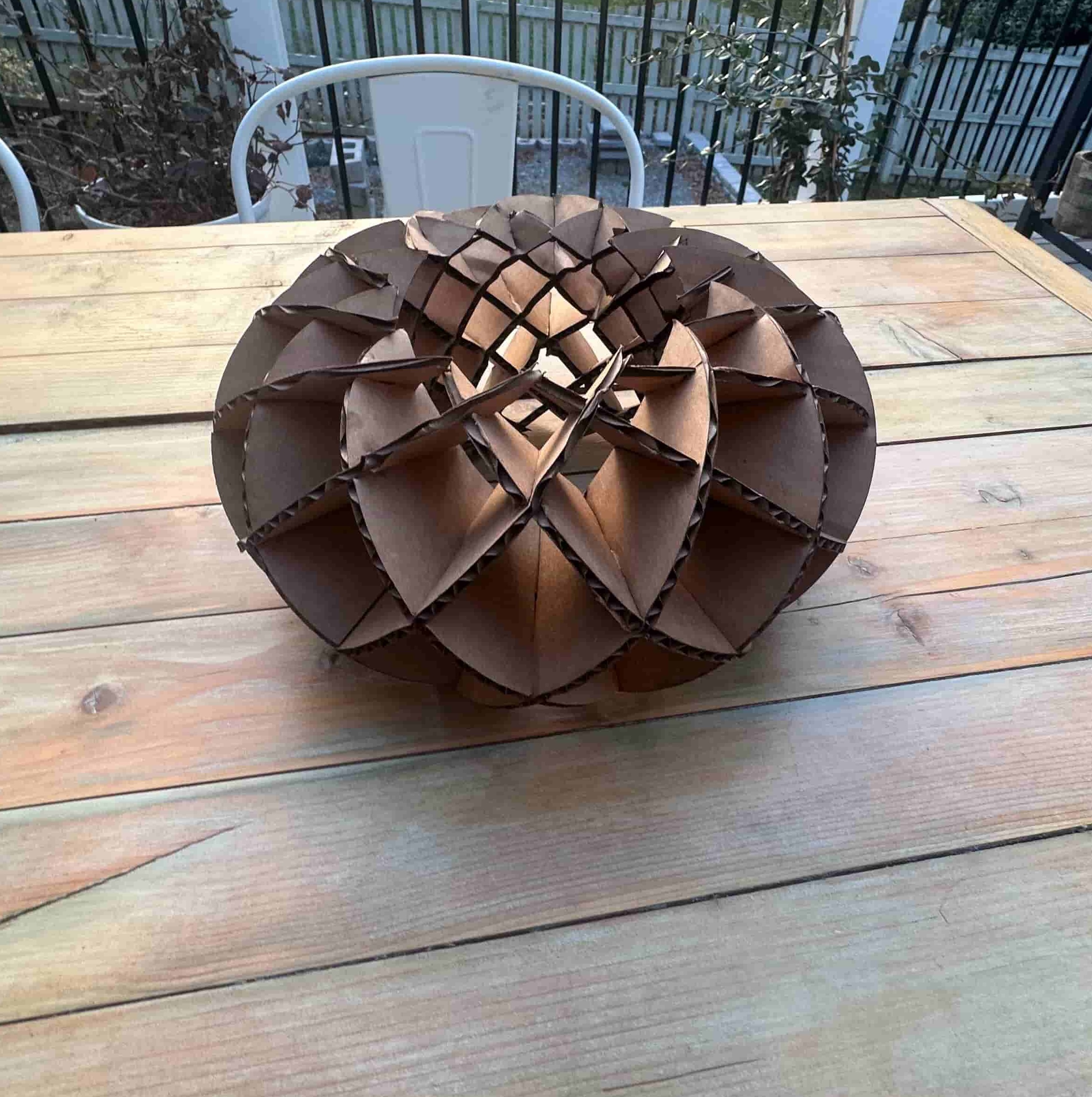
For my personal laser cut parametric construction kit, I was inspired by a sliceform torus design. This elegant geometric form is created by interlocking crescent-shaped pieces that assemble into a three-dimensional torus shape.
Design Inspiration
I found inspiration from this YouTube video that demonstrates the sliceform torus concept and provides a great explanation on how to assemble the design:
Design Process
CorelDRAW Design
I decided to start modeling this in CorelDRAW. I created 2 crescent moon shapes and added 6 grooves - one on the outside and the other on the inside of the crescent arch. Both grooves are aligned parallel, meaning if you were to continue drawing the line following from a crescent with the groove on the outside to the inside, it would be in the same spot.
The groove width is 3.53 mm, which matches the cardboard thickness I used for the project.
I also created a fully parametric version of the torus design in Fusion 360. The key advantage of parametric design is that you can change a single value — like material thickness — and the entire design updates automatically. Here's how I set it up:
Step 1: Adding User Parameters
In Fusion 360, I went to Modify → Change Parameters (or press S and search "parameters"). This opens the Parameters dialog where you can create custom variables. I clicked the + button under "User Parameters" and added:
cardboard_thickness = 3.53 mm — the measured thickness of my cardboard material
kerf = 0.254 mm (0.01 inch) — the laser kerf from our group testing
slot_width = cardboard_thickness + kerf — this is a formula, so it auto-calculates to 3.784 mm
The power of this approach: if I switch to a different material (say 3mm acrylic), I just change cardboard_thickness to 3.0 mm and every slot in the design updates instantly.
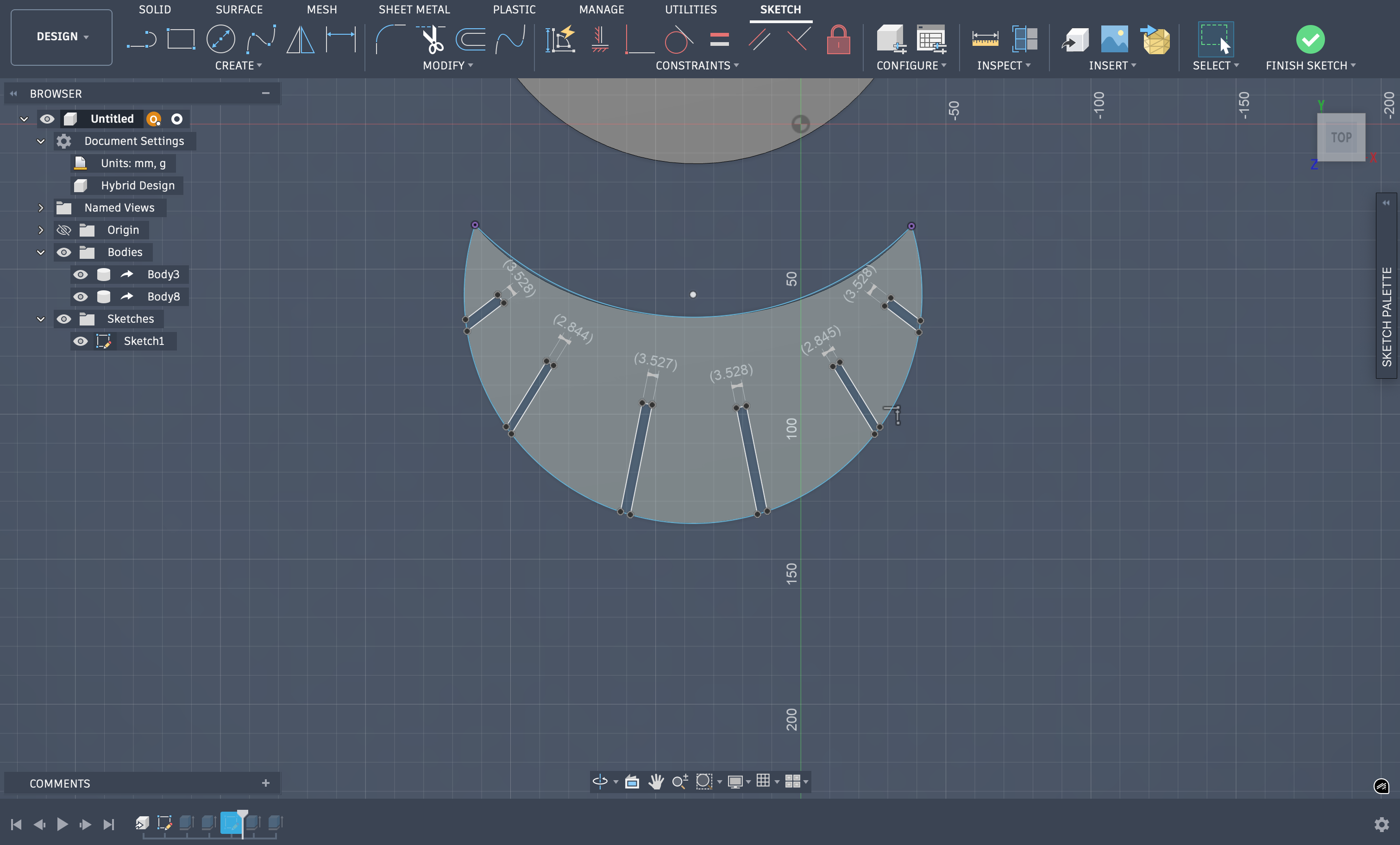
Step 2: Assigning Parameters to Sketch Dimensions
When sketching the crescent pieces, instead of typing a fixed number for the slot width, I typed the parameter name slot_width directly into the dimension input box. Fusion 360 recognizes it as a variable and links that dimension to the parameter. Any dimension in any sketch can reference these parameters — so every slot across both crescent piece types uses the same slot_width value.
I also constrained the overall crescent dimensions (outer radius, inner radius, arc angles) with parameters so the entire design is adjustable from the Parameters dialog without touching any sketches.
Step 3: Verifying the Parametric Constraints
To verify everything was linked correctly, I temporarily changed cardboard_thickness to a different value and confirmed that all slot widths updated throughout the design. Then I changed it back to 3.53 mm for the final cut.
Fusion 360 Parameters dialog — user parameters for cardboard thickness, kerf, and slot width with formula-based values
Note on File Formats: For 2D laser cutting, always use vector formats like DXF or SVG. These formats contain the actual cutting paths as lines and curves. STL files are for 3D models and are not suitable for laser cutting since they represent surfaces with triangular meshes rather than 2D cutting paths. The .f3d file above is the Fusion 360 native format which preserves the parametric design — you can open it in Fusion 360 and export to DXF or SVG for laser cutting.
Material Specifications
For this project, I used standard corrugated cardboard with the following specifications:
Material: Single-wall corrugated cardboard
Thickness: 3.53 mm (measured with calipers)
Color: Natural brown kraft
Flute Type: B-flute (medium thickness)
Why cardboard? Inexpensive, readily available, easy to cut, and perfect for prototyping construction kits before moving to more expensive materials like acrylic or wood
Epilog Laser Cutter Workflow
Our lab uses an Epilog Fusion Pro 48 laser cutter. Here's my complete workflow from design file to finished cut:
Step 1: Preparing the File
I designed the torus in CorelDRAW, creating the crescent shapes with the correct groove widths (3.53mm) to match my cardboard thickness. I made sure all my cutting paths were clean vector lines with no duplicate paths (which would cause the laser to cut the same path twice).
Step 2: Loading the File into CorelDRAW
Since I designed directly in CorelDRAW, the file was already in the correct format for the Epilog laser cutter. CorelDRAW serves as the print driver interface for the Epilog. I prepared the file by:
Set the page size to match the laser bed (48" × 36" for our machine)
Positioned my design in the upper-left corner of the page (this corresponds to the home position on the laser bed)
Set all cutting lines to Hairline width (0.001") and RGB Red (255, 0, 0) color — the Epilog driver interprets red hairlines as cut paths
If I had engraving areas, I would use black fills, but this design was cuts only
Step 3: Material Setup on the Laser Bed
Before sending the job, I prepared the material:
Placed the cardboard sheet flat on the laser bed
Made sure the material was completely flat — cardboard can warp, so I used small clips on the edges to hold the sheet down
Positioned the material in the upper-left area of the bed to match my CorelDRAW layout
Ensured there were no obstructions and the material wasn't overlapping any previous cuts or debris
Step 4: Auto-Focus
The Epilog Fusion Pro has an auto-focus feature that automatically sets the correct focal height for the material. The laser automatically zeros out and focuses on the material surface for optimal cutting.
Step 5: Configuring Cut Parameters
Back in CorelDRAW, I went to File → Print and selected the Epilog laser as the printer. The Epilog has preset settings for different materials stored in the machine. I selected the cardboard preset and used the following optimized settings for my 3.53mm cardboard:
Speed: 40% — optimized speed for clean cuts through cardboard
Power: 100% — full power to ensure complete cuts through the material
Frequency: 10% — lower frequency setting for cardboard
Vector Mode: Enabled (for cutting paths)
Air Assist: On — blows away smoke and prevents charring
These preset settings are stored in the Epilog machine and are optimized for cardboard. Different materials have different presets — acrylic, wood, and other materials each have their own optimized speed/power/frequency combinations.
Step 6: Safety Checks Before Cutting
Before hitting "Print" to send the job, I performed these safety checks:
✓ Exhaust fan running: The laser produces smoke and fumes that must be vented outside
✓ Lid closed: The laser will not fire with the lid open (safety interlock)
✓ Material is non-PVC: Never cut PVC or vinyl — it releases toxic chlorine gas. Cardboard is safe.
✓ Fire extinguisher nearby: Always know where it is. Cardboard can catch fire if settings are too high.
✓ Someone present: Never leave the laser unattended while cutting
✓ Clear cutting area: No debris or previous cut pieces that could interfere with the current job
Step 7: Running the Job
With everything set, I clicked Print in CorelDRAW. The job was sent to the laser cutter. On the Epilog control panel, I pressed the Go button to start the cut. I watched the entire process through the viewing window to ensure:
The laser was cutting cleanly through the material
No flames or excessive smoke (a little smoke is normal)
The cutting path matched my design layout
Since the torus design has two different crescent types (one with grooves on the inside, one with grooves on the outside), I had to run two separate cut files. Each sheet took about 14 minutes to cut, for a total of approximately 28 minutes of cutting time.
Step 8: Removing the Parts
After the laser finished and returned to home position, I waited 10 seconds for any smoke to clear, then opened the lid. I carefully removed the cut pieces from the bed, checking that all cuts went completely through the material. The pieces fit together perfectly, demonstrating the importance of accurate kerf compensation in parametric design.
Laser cutting the crescent pieces for the sliceform torus construction kit
Final Assembled Torus
The completed sliceform torus — all crescent pieces interlocked and assembled
Laser Cutting Tips
Always do a test cut with your material first
Verify kerf measurements before cutting final pieces
Ensure material is flat and secured to the bed
Check focus height for clean cuts
Monitor the cutting process for any issues
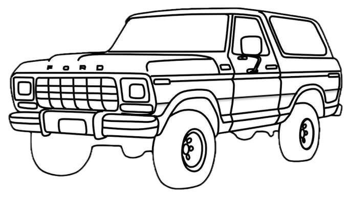
For the vinyl cutting project, I decided to create a Ford Bronco design. I wanted to incorporate the classic chromatic side stripes, but I knew it would be difficult to achieve the same color fade as the real vehicle. Instead, I split the stripes into three solid colors to better match what the vinyl cutter could produce.
Design Concept
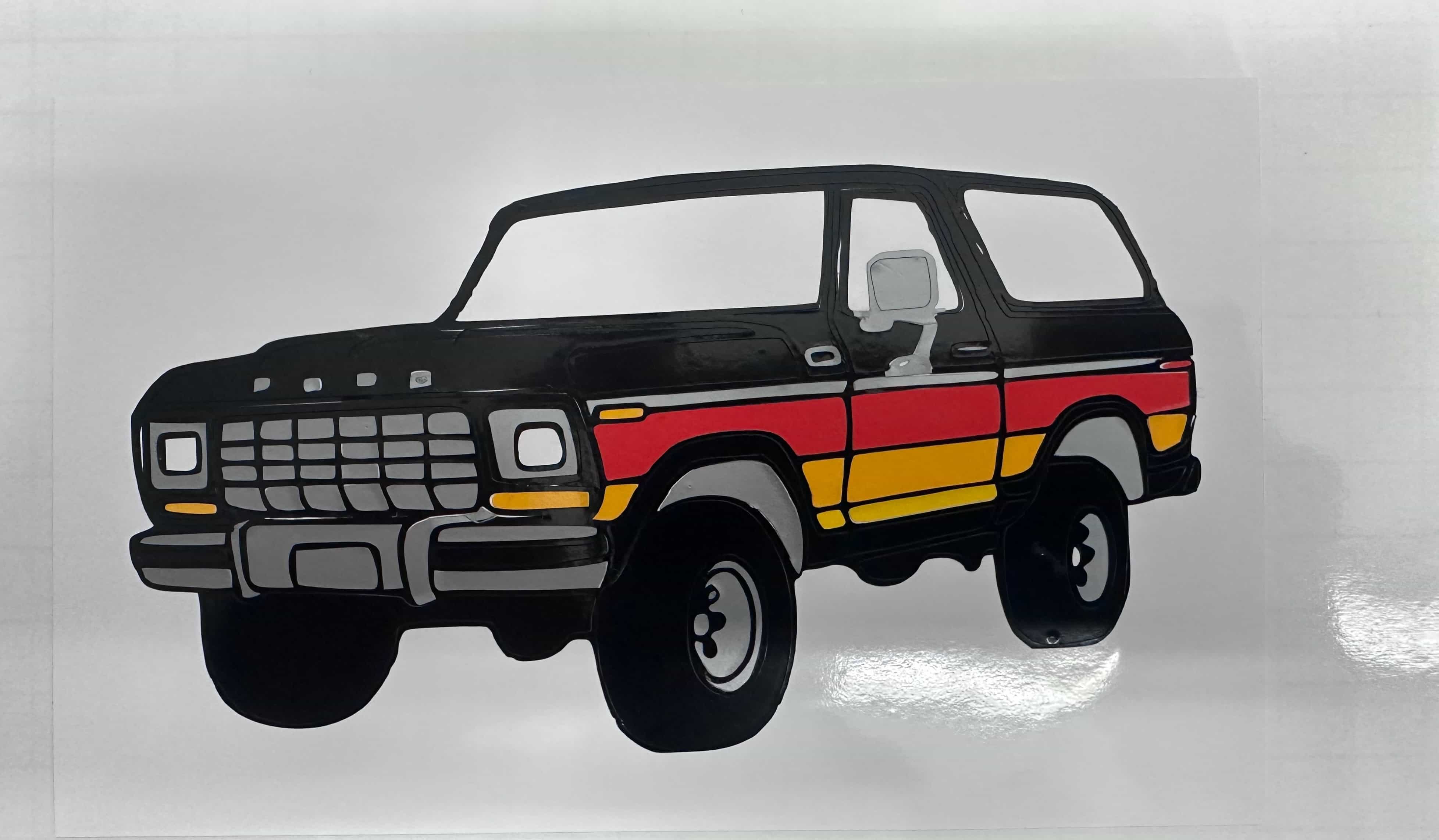
I chose a gray/silver color to add contrast and used a white background to help the design stand out. The colors I used were:
Black - Base layer and Bronco silhouette
Silver/Gray - Contrast and detail
Red - Chromatic stripe section
Yellow - Chromatic stripe section
Orange - Chromatic stripe section
White - Background layer for contrast
Layering Process
For most of the colors, I cut the exact same Bronco shape, removed the sections I didn't need, and layered the correct colored pieces onto the black base. The white layer was done differently. I added it after finishing the other layers because I believe it improves the overall contrast, especially since the stickers will be placed on the lab window.
Cutting & Assembly
I cut the design using a Cricut machine to ensure clean, precise edges. The multi-layer approach required careful alignment to ensure each color piece fit perfectly on the base layer.
For the background of the Bronco, I used Silhouette Studio and cut it at school to gain more experience with other software and devices. The basics are the same as my Cricut at home, so I was able to do it pretty quickly.
Multi-color Ford Bronco vinyl cut with chromatic stripes
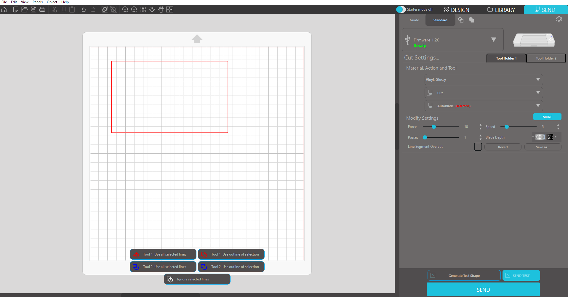
Silhouette Studio cut settings for the Bronco background
.jpg)