12. Mechanical Design, Machine Design
This week our group designed and built a prototype XIAO Vending Machine — a
column-based dispenser that releases Seeed Studio XIAO boards when a user taps a pre-programmed
RFID card. My individual contribution was to explore the STS3215 serial bus servo:
understand how it works, bring up the Waveshare SCServo library on the Wio Terminal,
assign unique IDs, tune gate positions, and deliver the servo test code that the team integrated
into the final firmware.
Assignment checklist
- Linked to the group assignment page
- Documented my individual contribution — STS3215 exploration and servo bring-up
- Explained how the STS3215 serial bus servo works (protocol, wiring, position control)
- Generated and shared related test code used in the group project
- Outlined problems encountered during servo testing and how I fixed them
- Included source code and links to the group design files
Group Assignment — XIAO Vending Machine
The full group documentation covers ideation, planning, mechanical assembly, RFID integration, and the final demo video. The machine flow is:
contains
TRUE tokenvalidates payment
open column gates
output chute
Week 12 Group Assignment — Mechanical Design / Machine Design (Chaihuo Fab Lab)
My Role — Exploring the STS3215
While other teammates focused on the enclosure, RFID writer, and mechanical column design, I took ownership of the actuator subsystem. Before we could integrate servos into the vending machine, we needed to answer several questions:
- How does a serial bus servo differ from the PWM SG90 I used in Week 11?
- How do we wire and power multiple STS3215 units on a single data line?
- How do we assign unique IDs when every servo ships with ID 1?
- What position values open and close the dispensing gate reliably?
I worked through these step by step on a Wio Terminal, producing three standalone test sketches
and the gate-motion parameters (HOME_POS = 1024, TRIGGER_POS = 0,
two dispense cycles) that the team merged into
vending_machine_final_code.ino.
| Task | What I did | Output |
|---|---|---|
| Research | Read Waveshare ST3215/STS3215 wiki, protocol manual, and compared bus vs PWM servos | Spec table and wiring notes (below) |
| ID assignment | Flashed change-ID sketch one servo at a time; assigned IDs 1 and 2 | STS3215_change_id.ino |
| Single-servo demo | Verified UART communication and position feedback on one unit | STS3215_demo_sweep.ino |
| Dual-servo gate test | Used SyncWritePosEx to move both servos together; tuned speed, acceleration, and delays |
STS3215_gate_test.ino |
| Integration support | Shared position values and timing constants with the team for RFID-triggered dispense | Group final firmware (GitLab link below) |
How the STS3215 Works
Why not a normal PWM servo?
In Week 11 I controlled an SG90 with a 50 Hz PWM pulse — one signal wire per servo, no feedback, and no way to know the actual horn angle. The STS3215 is a smart serial bus servo (Feetech / Waveshare ST series). Instead of PWM, it speaks a structured UART protocol over a single half-duplex data line. Multiple servos daisy-chain on that one bus, each addressed by a unique ID from 1 to 253.
| Feature | SG90 (PWM, Week 11) | STS3215 (Serial Bus) |
|---|---|---|
| Control signal | 50 Hz PWM pulse width | Half-duplex UART @ 1 Mbps (default) |
| Wiring | One signal wire per servo | Single daisy-chained data bus (GND + VCC shared) |
| Addressing | None — wired to a GPIO pin | Unique ID (0–253), set via EEPROM |
| Position resolution | ~180° analog pulse, no readback | 360° / 4096 steps (12-bit magnetic encoder) |
| Feedback | None | Position, load, speed, input voltage |
| Multi-servo control | Needs one GPIO per servo | SyncWritePosEx — one packet, all servos move together |
First principles: half-duplex UART bus
The STS3215 uses half-duplex communication — one data wire carries traffic in both directions, but only one device transmits at a time. The Wio Terminal (master) sends a command packet; every servo on the bus listens; only the servo whose ID matches executes the instruction and optionally replies with feedback.
Wio Terminal TX/RX → single DATA wire → Servo A (port A ↔ port B) → Servo B → …
Each servo has two 3-pin ports (A and B) so the signal passes through the chain. Power (6–12.6 V) and GND run alongside the data line. Because locked-rotor current can reach 2.7 A per servo, the team powered the bus from a dedicated 7.4 V supply rather than the Wio Terminal's 5 V pin.
Packet structure
The protocol follows the Feetech / Waveshare Smart Bus Servo format. Every instruction packet looks like this:
| Byte | Field | Meaning |
|---|---|---|
| 0–1 | Header | 0xFF 0xFF — start of packet |
| 2 | ID | Target servo ID (or 0xFE for broadcast) |
| 3 | Length | Number of bytes following |
| 4 | Instruction | PING, READ, WRITE, SYNC WRITE, etc. |
| 5… | Parameters | Register address, position, speed, acceleration |
| last | Checksum | ~(ID + Length + Instruction + Params) |
Position is a signed 16-bit value from 0 to 4095 representing 360°. The vending machine gate
uses a 90° swing: HOME_POS = 1024 (gate closed) and TRIGGER_POS = 0
(gate open). The Waveshare SCServo library wraps all of this into high-level calls
like WritePosEx(), ReadPos(), and SyncWritePosEx().
Key specifications
| Parameter | Value |
|---|---|
| Operating voltage | 6 – 12.6 V |
| Torque | 30 kg·cm @ 12 V |
| Position resolution | 360° / 4096 |
| Default baud rate | 1 000 000 bps |
| ID range | 0 – 253 (factory default: 1) |
| Max daisy-chain | 253 servos (power-limited in practice) |
| Feedback | Position, load, speed, input voltage |
| Connector | 3-pin: GND, VCC, DATA (per port) |
Hardware Setup — Wio Terminal + STS3215
On the Wio Terminal, the Grove UART port maps to Serial1. I connected the servo
bus DATA line to the UART pins and kept RFID on the separate I²C Grove port (Wire1),
so both subsystems could run simultaneously in the final firmware.
| Connection | Wio Terminal | STS3215 bus |
|---|---|---|
| Data (RX) | PIN_WIRE_SCL → Serial1 RX | DATA |
| Data (TX) | PIN_WIRE_SDA → Serial1 TX | DATA (same wire) |
| Power | External 7.4 V supply | VCC (both servos) |
| Ground | GND (common with Wio) | GND |
| RFID reader | Grove I²C (Wire1, addr 0x28) | — |

My Testing Process
-
1
Install the SCServo library — copied
scservo-mainfrom the group repo into Arduinolibraries/. This provides theSMS_STSclass for the ST/STS series. -
2
Assign unique IDs — connected one servo at a time and ran
STS3215_change_id.ino. Verified each ID withst.Ping(id)before connecting the next servo to the chain. -
3
Single-servo sweep — ran
STS3215_demo_sweep.inoto move one servo through positions 0 → 1024 → 2048 → 1024 → 0 and read back actual position withReadPos(). This confirmed the magnetic encoder feedback loop works. -
4
Dual-servo gate motion — daisy-chained both servos (IDs 1 and 2) and ran
STS3215_gate_test.ino. UsedSyncWritePosExso both gates open and close in sync. TunedSpeed = 1500,ACC = 50, forward delay 1800 ms, return delay 1200 ms. - 5 Hand off to integration — shared the position constants and timing values with teammates who merged them into the RFID-triggered final firmware on the Wio Terminal.
Gate Motion Code
The core dispense function I developed moves both servos together using synchronous write.
This is the same pattern used in the group's
vending_machine_final_code.ino:
Dual-servo gate cycle (from STS3215_gate_test.ino)
#define SERVO_NUM 2
byte ID[SERVO_NUM]    = {1, 2};
u16  Speed[SERVO_NUM] = {1500, 1500};
byte ACC[SERVO_NUM]   = {50, 50};
s16  Pos[SERVO_NUM]   = {1024, 1024};

const s16 HOME_POS    = 1024;   // gate closed
const s16 TRIGGER_POS = 0;      // gate open

void moveBothTo(s16 target) {
  for (int i = 0; i < SERVO_NUM; i++) Pos[i] = target;
  st.SyncWritePosEx(ID, SERVO_NUM, Pos, Speed, ACC);
}

void runGateCycles(byte cycles) {
  for (byte c = 0; c < cycles; c++) {
    moveBothTo(TRIGGER_POS);
    delay(1800);
    moveBothTo(HOME_POS);
    delay(1200);
  }
}
Integration in the Group Project
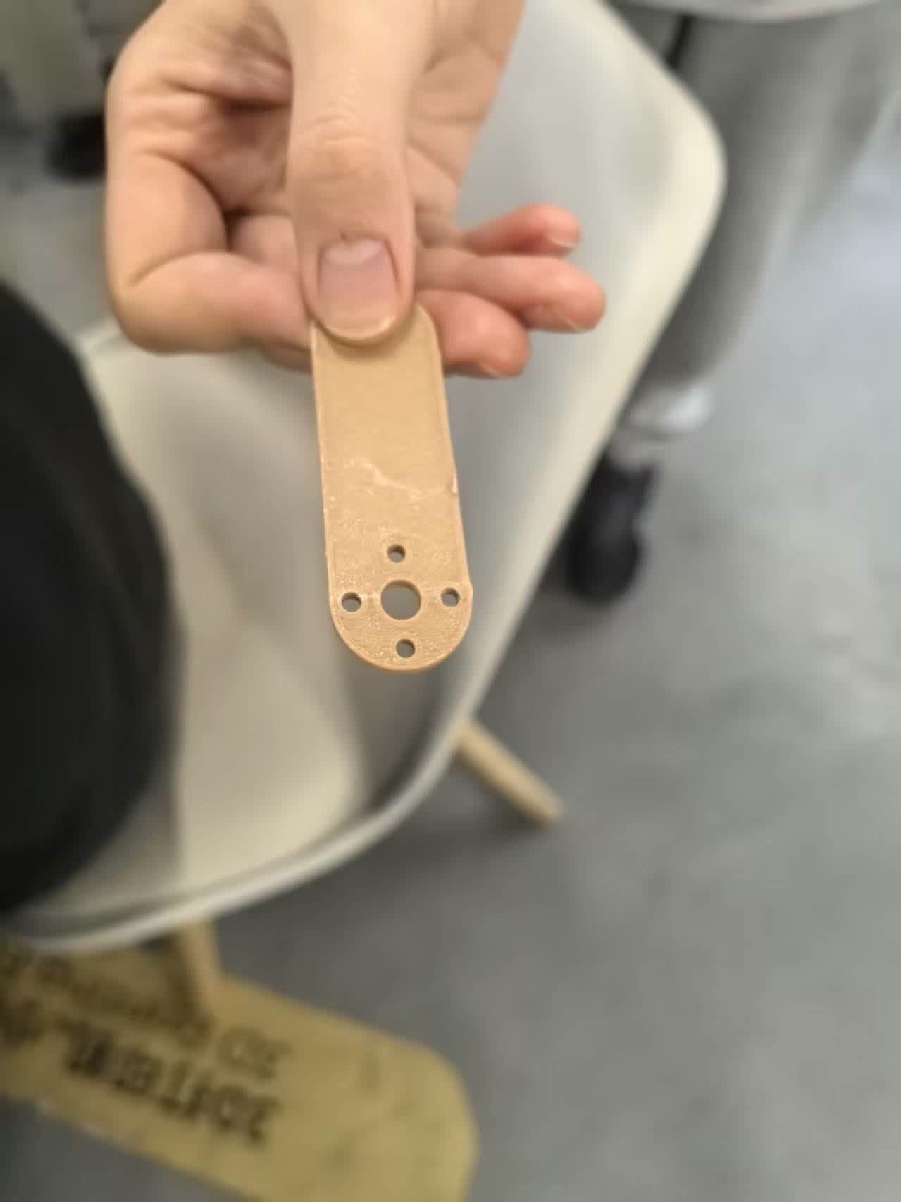
Once the gate motion was reliable on the bench, the team mounted each STS3215 to a 3D-printed
arm that pushes the column gate. The full system test — RFID card tap → Wio Terminal validates
TRUE token → two HOME → TRIGGER → HOME cycles on both servos → one
XIAO board drops — is documented on the
group page
(sections 5–7).
insert video:
The final firmware reads MIFARE block 4 over I²C and, on a TRUE match, calls
the same runDispenseCycles(2) function. Running two cycles ensures the XIAO board
clears the gate even if the first push only loosens the stack.
Problems and How I Fixed Them
When I daisy-chained two STS3215 units, both horns moved whenever I addressed ID 1. Every servo ships from the factory with ID 1.
Connected only one servo to the bus at a time and ran the change-ID sketch to assign ID 1
and ID 2 separately. Verified with Ping(1) and Ping(2) before
chaining them together.
On early tests the servo buzzed but the horn barely moved, or the Wio Terminal reset when both servos started simultaneously.
The STS3215 needs 6–12.6 V and up to 2.7 A per servo under load. Powering from the Wio Terminal's 5 V pin was insufficient. Switching to a dedicated 7.4 V supply and tying GND to the Wio Terminal resolved both the weak torque and the brown-out resets.
A single open-close cycle sometimes left the bottom board stuck in the column — the gate opened but the board did not fall.
Increased the forward delay to 1800 ms so the arm fully clears the column opening, and set
DISPENSE_CYCLES = 2 in the final firmware. The second push dislodges any board
that did not drop on the first attempt.
Using the default Serial1.begin(9600) produced no movement and
Ping() returned errors.
The STS3215 defaults to 1 000 000 bps. Changed initialization to
Serial1.begin(1000000, SERIAL_8N1, SERVO_RX, SERVO_TX) and assigned
st.pSerial = &Serial1 before any other calls.
What I Learned
The biggest takeaway is that serial bus servos change how you think about actuators. With a PWM servo you send a pulse and hope; with the STS3215 you send a structured command, read back the actual position, and can synchronously move an entire chain from one UART port. This is exactly what the vending machine needs — two gates must open and close together, and the team can add more columns later by daisy-chaining additional servos with new IDs.
I also learned that bus servo bring-up has a specific order: correct baud rate → assign IDs → single-servo test → multi-servo sync write → mechanical integration. Skipping the ID step or under-powering the bus causes problems that look like firmware bugs but are really wiring issues.
Design Files & Source Code
My individual sketches
- STS3215_change_id.ino — assign unique bus IDs
- STS3215_demo_sweep.ino — single-servo position sweep + feedback
- STS3215_gate_test.ino — dual-servo gate motion test
Group repository (GitLab)
- code_servo/ — SCServo library and all group servo sketches
- vending_machine_final_code/ — final Wio Terminal firmware
- test_for_assemble/ — first RFID + servo integration sketch
References
Hero Shot
STS3215 servos daisy-chained on the Wio Terminal, driving the vending machine column gates.