11. Networking and Communications
This week I implemented wireless communication between a Seeed XIAO ESP32-C3 (ultrasonic input) and a Seeed XIAO ESP32-S3 (servo output) using ESP-NOW — Espressif's peer-to-peer, connection-less radio protocol. I also participated in the group assignment to send messages between populated PCB nodes over wired and wireless links. Board A reuses my Week 8 XIAO ESP32-C3 carrier PCB from Week 9; Board B is a XIAO ESP32-S3 on a breadboard.
The system works as follows: Board A (ESP32-C3) reads distance from an HC-SR04 ultrasonic sensor and sends the value over ESP-NOW to Board B (XIAO ESP32-S3), which maps distance to a SG90 servo angle — the closer the object, the farther the servo rotates (up to 180 °).
Assignment checklist
- Linked to the group assignment page
- Documented the project and what I learned from implementing networking/communication
- Explained the programming process(es) used
- Ensured and documented that addressing for boards works
- Outlined problems and how I fixed them
- Included design files and a hero shot of the network setup
Group Assignment — Send a Message Between Two Projects
The group brief was to send a message between two projects — connecting populated PCBs and microcontroller nodes from earlier weeks over wired and wireless links. We built on the carrier boards from Week 6 and Week 8, with XIAO modules, I²C OLEDs, and Grove radios soldered to the designed buses rather than loose breadboard jumpers.
Week 11 Group Assignment — Networking and Communications (Chaihuo Fab Lab)
Platform — PCB nodes connected
Each node in the group setup combines:
- A populated carrier PCB or XIAO breakout with soldered headers
- I²C OLED (status display) on the designed SDA/SCL pins
- Wireless module — BLE (on-board ESP32), or Grove LoRa 868 MHz (UART)
- Common 3.3 V / 5 V rails and ground tied across probes and radios
Messages travel over the buses and radios we designed into the board — the networking tests exercise the full stack, not just a dev kit on a breadboard.
Earlier group experiments — direct node-to-node
Before the MQTT + LoRa integration, the cohort tested direct communication between two nodes:
| Experiment | Nodes | Bus / link | Result |
|---|---|---|---|
| Bluetooth BLE | 2× XIAO ESP32-C3 + OLED | BLE (2.4 GHz) | Server advertises; client scans and connects. Range ~10 cm without antenna, >10 m with two IPEX antennas. |
| I²C decode | XIAO ESP32-C3 + OLED | I²C (wired) | Logic analyzer captured 0x3C write packets updating the OLED framebuffer. |
| SPI / RFID | Raspberry Pi 4 + MOSFET + LED | SPI (wired) | Proof-of-concept load switch; CS/CLK/MOSI/MISO visible on the analyzer. |
Lessons from these tests:
- Wireless needs both sides defined — server/client roles, reconnect logic, and OLED feedback.
- Antennas matter — ESP32-C3 BLE without an IPEX antenna is usable on the bench only.
- I²C is wired networking — address byte + ACK; same decode skills as Week 9 scope work.
- Two-node messaging is harder than one-direction UART — manage state on both microcontrollers.
Wireless technology comparison
| Technology | Range | Frequency | Data rate | Internet |
|---|---|---|---|---|
| Wi-Fi | 50–100 m | 2.4 / 5 GHz | 10–600 Mbps | Yes (via AP) |
| Bluetooth BLE | 10–50 m | 2.4 GHz | 125 kbps–2 Mbps | Via gateway |
| LoRa | 2–15 km | 433 / 868 / 915 MHz | 0.3–50 kbps | No (needs LoRaWAN) |
Higher frequency → more data, shorter range. LoRa trades speed for distance — good for field nodes that should not depend on Wi-Fi.
Wired/wireless integration — MQTT + WiFi + LoRa
Taking the two-node work further, we tested wireless communication between multiple units of the solar PV final-project concept: location detection and bidirectional command exchange. A WiFi + LoRa combination was chosen as robust for mixed indoor/outdoor use. Because cloud services and a payment system are planned later, MQTT was added so the embedded chain mirrors a realistic IoT publish/subscribe flow.
Basics of MQTT
MQTT (Message Queuing Telemetry Transport) uses a publish/subscribe model:
| Role | Function |
|---|---|
| Broker | Central server (we used Mosquitto) — receives and routes messages |
| Publisher | Sends messages to a topic (e.g. lora/tx) |
| Subscriber | Receives messages from topics it subscribed to |
Devices do not talk to each other directly — they talk through the broker. This decouples the WiFi-connected node from the LoRa-only node.
Two-node MQTT + LoRa setup
| Node (left) | Node (right) |
|---|---|
| XIAO ESP32-C3 + Grove LoRa 868 MHz + OLED WiFi + MQTT subscriber Forwards MQTT messages over LoRa UART |
XIAO RP2040 + Grove LoRa 868 MHz + OLED LoRa receiver only Processes commands on display |
The RP2040 has no built-in Wi-Fi — it depends on LoRa from the ESP32-C3, reducing reliance on internet at the remote node.
topic: lora/tx
port 1883
LoRa UART TX
OLED display
LoRa wiring (both boards):
| LoRa pin | XIAO pin |
|---|---|
| TX | D7 (MCU RX) |
| RX | D6 (MCU TX) |
| VCC | 3.3 V |
| GND | GND |
OLED (I²C, both boards): SDA → D4, SCL → D5
End-to-end flow:
- ESP32-C3 connects to WiFi and subscribes to MQTT topic
lora/tx - PC publishes via
mosquitto_pub→ broker → ESP32-C3 callback - ESP32-C3 forwards the string over LoRa UART to RP2040
- RP2040 shows the message on the OLED
Test commands we used in the lab:
mosquitto_pub -t "lora/tx" -m "Hello ESP32"
mosquitto_pub -t "lora/tx" -m "turn on the system"
mosquitto_pub -t "lora/tx" -m "turn off the system"
What I learned from the group work
| Topic | Key takeaway |
|---|---|
| PCB nodes as integration point | Radios and OLEDs mount on the same boards we designed and fabricated — networking tests the full stack, not just a dev kit. |
| Pick the link for the job | BLE for short-range peer pairing; LoRa for longer range without Wi-Fi; MQTT when a PC or cloud service must inject commands. |
| Brokers decouple nodes | The ESP32-C3 and RP2040 never need a direct IP path to each other — only to the broker (ESP32) and LoRa link (both). |
| Antennas and UART wiring | Swapped TX/RX or a missing IPEX antenna shows up immediately as silent radios or dropped BLE. |
| Test with known strings first | Hello ESP32, turn on the system, turn off the system made it obvious when each hop in the chain worked. |
These group findings informed my individual assignment: I chose ESP-NOW for direct ESP32-to-ESP32 control with no broker or router — a different trade-off than the group's MQTT + LoRa chain, but the same underlying idea of defining addresses, roles, and feedback on both nodes.
Individual Assignment — ESP-NOW Ultrasonic → Servo
Goal: connect an input device on one board and an output device on another, and exchange data wirelessly. A XIAO ESP32-C3 with HC-SR04 measures distance; an XIAO ESP32-S3 drives the servo — no wire between the two nodes.
Communication Protocol Comparison
Before choosing a protocol, I compared the main options available on the ESP32 platform. The table below summarises the key characteristics of each method and explains why I selected ESP-NOW for this project.
| Method | Common Pins | Wired / Wireless | Typical Use | Speed | Range | Good For | Main Limitation |
|---|---|---|---|---|---|---|---|
| UART / Serial | TX, RX | Wired | Board-to-board, PC debugging, modules like GPS / DFPlayer | Medium | Short | Simple communication between two devices | Usually one-to-one |
| I²C | SDA, SCL | Wired | Sensors, OLEDs, RTC, multiple devices | Medium | Short | Many devices on just 2 signal wires | Short distance, address conflicts possible |
| SPI | MOSI, MISO, SCK, CS | Wired | Displays, SD cards, fast sensors, radio modules | Fast | Short | High-speed communication | Uses more pins |
| Wi-Fi | Built into ESP32 / ESP8266 | Wireless | IoT, web server, remote control, sending data online | Fast | Medium | Internet, phone / web dashboard | Higher power use |
| Bluetooth / BLE | Built into ESP32 | Wireless | Phone control, apps, nearby device connection | Medium | Short | Easy phone-to-board communication | Shorter range than Wi-Fi |
| Radio (RF) | Often via SPI modules | Wireless | Remote control, board-to-board wireless | Varies | Medium to long | No Wi-Fi needed | Needs extra module |
| CAN Bus | CAN TX/RX + transceiver | Wired | Automotive, robotics, robust multi-device systems | Medium | Long | Reliable in noisy environments | Extra hardware needed |
| ESP-NOW ✓ | ESP32 / ESP8266 wireless | Wireless | Direct ESP-to-ESP communication | Fast | Medium | No router needed, low latency | Mostly for ESP family only |
Why I chose ESP-NOW — and ruled out the alternatives
My project needs two ESP32 boards to communicate in real time: as the ultrasonic reading on Board A changes, the servo on Board B must follow with no noticeable delay. Here is why I rejected each alternative:
- Wi-Fi — requires a router (or one board acting as a software access point). Connection setup takes seconds, and even after connecting, the TCP/IP stack adds latency that makes servo responses feel sluggish. Wi-Fi is the right choice when you need internet access or a web dashboard, but not for fast local control.
- Bluetooth / BLE — designed primarily for phone-to-board communication. Setting up a board-to-board BLE connection requires a GATT server/client pairing process that is significantly more complex than ESP-NOW. Typical BLE round-trip latency is 15–50 ms, compared to <5 ms for ESP-NOW. For a robotic arm where smooth motion matters, this difference is noticeable.
- Radio (RF modules such as nRF24L01 or LoRa) — would require soldering an external SPI module to each board, increasing wiring complexity and cost. Since the ESP32 already has a built-in 2.4 GHz radio that ESP-NOW can use directly, adding external RF hardware would be redundant.
- UART / I²C / SPI (wired) — perfectly valid for short distances, but a physical cable between the two boards defeats the purpose of demonstrating networking. The assignment specifically asks for board-to-board communication, and a wireless link is more interesting to document and demonstrate.
ESP-NOW wins because: both boards are Espressif ESP32-family chips (C3 and S3),
the latency is <5 ms (servo tracks hand motion smoothly), no router or infrastructure is needed,
the API is straightforward — register a peer by MAC address and call
esp_now_send(). For a robotic arm lamp that needs real-time local control,
it is the right tool for the job.
Note: if the lamp later needs phone app control, I would add BLE on top of ESP-NOW. If it needs to log data to a server, I would add Wi-Fi. ESP-NOW and Wi-Fi can even run simultaneously on the same ESP32.
What is the first principle behind ESP-NOW?
At the most fundamental level, ESP-NOW works because two ESP32 boards use their built-in 2.4 GHz Wi-Fi radio hardware to send and receive specially formatted wireless frames directly, without needing a router or a normal Wi-Fi network connection.
So the core idea is:
- ESP-NOW is not a completely different radio system.
- It uses the same Wi-Fi hardware inside the ESP32, but instead of connecting to a router and using TCP/IP, it sends small direct packets from one ESP32 to another.
First-principles view: what is wireless communication?
Wireless communication is simply this:
- One device converts digital data (0s and 1s) into electromagnetic signals.
- Those signals are transmitted through the air using a radio frequency.
- Another device listening on the same frequency receives the signal.
- It converts the signal back into digital data.
For ESP32, this happens using its 2.4 GHz Wi-Fi radio. So when two ESP32 boards communicate with ESP-NOW, they are really doing this:
- one ESP32 uses its antenna and Wi-Fi hardware to radiate a signal
- the other ESP32 listens for that signal
- if the message format matches ESP-NOW and the address matches, it accepts the data
How do two ESP32 boards communicate without a router?
Normally, Wi-Fi communication looks like this:
Device → Router → Network → Another device
But ESP-NOW skips the router. Instead, it works more like this:
ESP32 A → direct wireless packet through the air → ESP32 B
So ESP-NOW is a peer-to-peer communication method. That is why it is fast and lightweight.
What happens step by step?
Here is the real process:
On ESP32 A:
- Wi-Fi hardware is turned on.
- ESP-NOW is initialized.
- ESP32 B is added as a peer using its MAC address.
- A program calls
esp_now_send(). - The ESP32 packages the data into a special wireless frame.
- Its antenna transmits that frame through the air.
On ESP32 B:
- Its Wi-Fi hardware is listening on the same channel.
- It receives the frame.
- It checks whether the address matches.
- If valid, the received data is passed to the receive callback function.
So from first principles: ESP-NOW is direct device-to-device wireless packet delivery using Wi-Fi radio hardware, but without traditional networking layers.
Why is ESP-NOW so useful?
Because it avoids a lot of extra overhead.
With normal Wi-Fi, you usually need:
- a router
- connection setup
- an IP address
- a full network protocol stack
With ESP-NOW, you can just send short data directly.
That makes it very useful for:
- sensor nodes
- remote controls
- robots
- smart lamps
- communication between multiple ESP32 boards
System Architecture
HC-SR04 on D1 / D2
Sends distance (cm)
Peer MAC address
No router needed
SG90 on D8 (GPIO7)
Serial debug output
I chose ESP-NOW over standard Wi-Fi for three reasons:
- No router required — the two boards talk directly, making the setup fully standalone.
- Very low latency — packets are delivered in < 5 ms, so the servo tracks hand motion smoothly.
- Simple API — after registering a peer by MAC address, sending a float distance is a single
esp_now_send()call.
Distance → servo mapping: Board B maps 5 cm (hand close) to 180° and 50 cm (hand far) to 0°, using the same inverse relationship as my Week 10 NeoPixel brightness demo — closer target, stronger output response.
Circuit Design & Wiring
Board A reuses the populated Week 8 XIAO ESP32-C3 carrier PCB. Board B is a Seeed XIAO ESP32-S3 on a breadboard; I documented the servo circuit in Cirkuit Designer before wiring.
Board A — Ultrasonic Sender (XIAO ESP32-C3)
An HC-SR04 ultrasonic module measures distance to a nearby object, wired to my
Week 8 XIAO ESP32-C3 carrier board — the same setup as
Week 9. The sensor needs 5 V on VCC; Trig and Echo
connect to D1 and D2. Board A averages five samples per reading, then
transmits the distance in centimetres over ESP-NOW whenever the value changes by more than 1 cm.
| HC-SR04 pin | XIAO ESP32-C3 pin | Notes |
|---|---|---|
| VCC | 5V | Sensor requires 5 V supply |
| GND | GND | Common ground |
| Trig | D1 (GPIO3) | Digital output — 10 µs trigger pulse |
| Echo | D2 (GPIO4) | Digital input — echo pulse width |
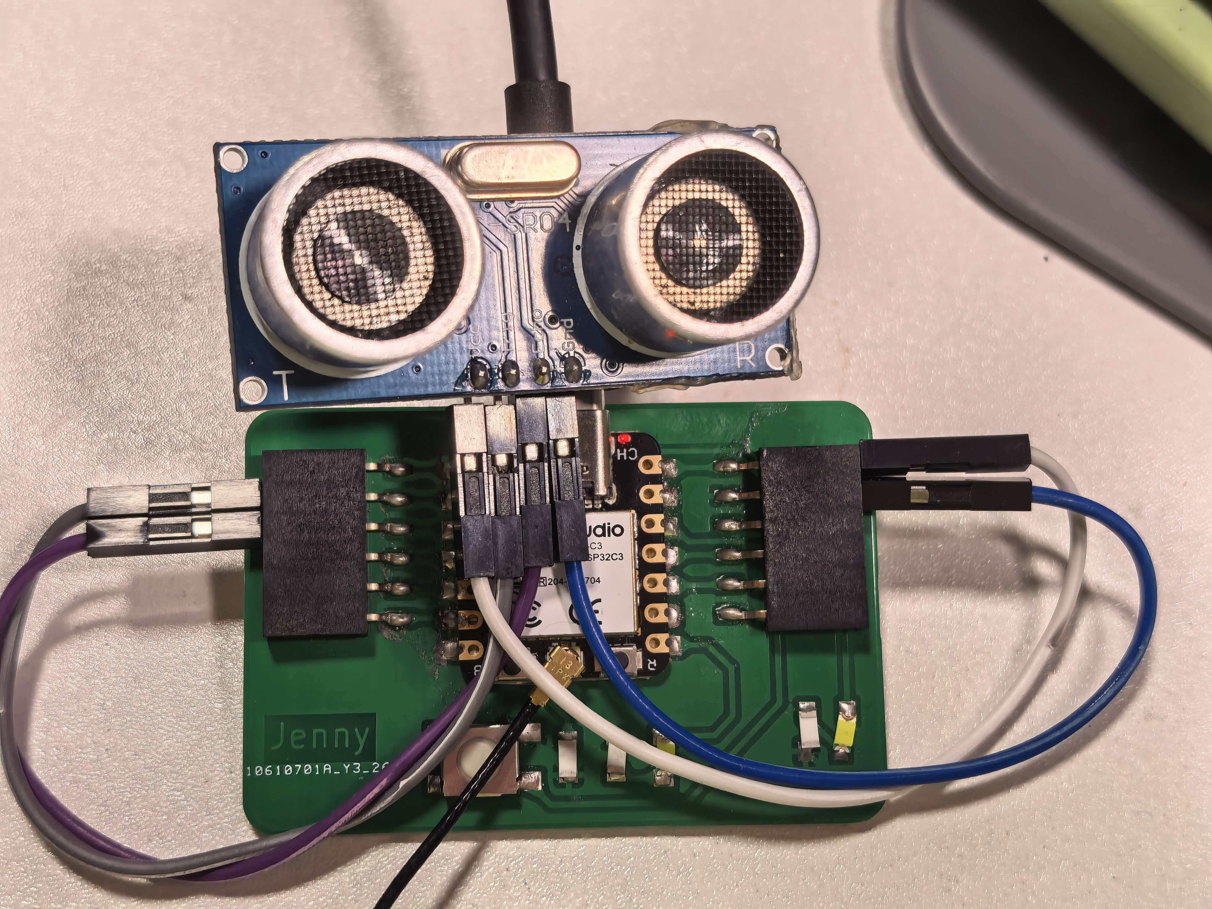
Board A — HC-SR04 on the Week 8 XIAO ESP32-C3 carrier PCB (5V, GND, D1 Trig, D2 Echo).
Board B — Servo Receiver (XIAO ESP32-S3)
The SG90 servo signal wire connects to D8 (GPIO7), which supports LEDC PWM on the XIAO ESP32-S3. Servo power uses 5V and GND; a 100 µF capacitor across the servo supply absorbs inrush current when the motor stalls.
| SG90 wire | XIAO ESP32-S3 pin | Notes |
|---|---|---|
| Signal (orange) | D8 (GPIO7) | PWM control — avoid D4/D5 (I²C) and D6/D7 (UART0) |
| VCC (red) | 5V / VBUS | 5 V servo supply from USB |
| GND (brown) | GND | Common ground with the board |
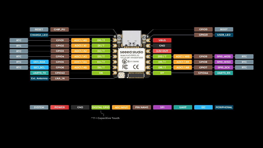
XIAO ESP32-S3 pinout — D8 (GPIO7) for servo PWM; 5V / VBUS for servo power.
Board Addressing
ESP-NOW uses the standard Wi-Fi MAC address of each ESP32 as its unique network identifier. There is no IP layer or DHCP — the sender simply registers the receiver's 6-byte MAC address as a "peer" and sends packets directly to it.
How I found the MAC addresses
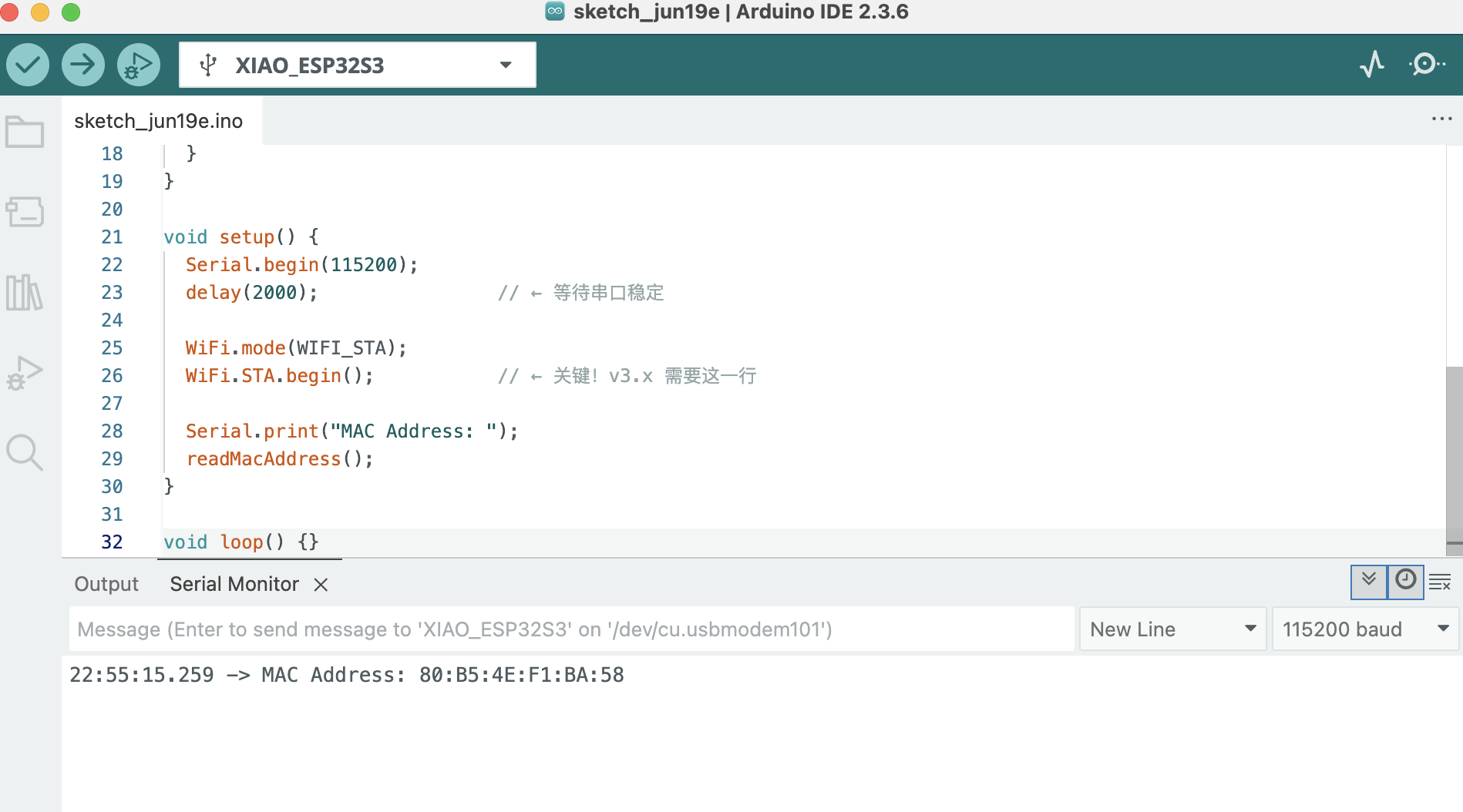
I uploaded the sketch below to each board (XIAO ESP32-C3 and XIAO ESP32-S3) and read the MAC
address from the Serial Monitor at 115200 baud. On ESP32 Arduino Core v3.x,
WiFi.macAddress() alone can fail — use esp_wifi_get_mac() after
WiFi.STA.begin():
GetMacAddress_Fixed.ino
Firmware: GetMacAddress_Fixed.ino — ESP32 Arduino Core v3.x (XIAO ESP32-C3 / S3)
/*
 * GetMacAddress_Fixed.ino
 * ESP32 Arduino Core v3.x (XIAO ESP32-C3 / S3)
 */

#include <WiFi.h>
#include <esp_wifi.h>

void readMacAddress() {
  uint8_t baseMac[6];
  esp_err_t ret = esp_wifi_get_mac(WIFI_IF_STA, baseMac);
  if (ret == ESP_OK) {
    Serial.printf("%02X:%02X:%02X:%02X:%02X:%02X\n",
                  baseMac[0], baseMac[1], baseMac[2],
                  baseMac[3], baseMac[4], baseMac[5]);
  } else {
    Serial.println("Failed to read MAC address");
  }
}

void setup() {
  Serial.begin(115200);
  delay(2000);

  WiFi.mode(WIFI_STA);
  WiFi.STA.begin();

  Serial.print("MAC Address: ");
  readMacAddress();
}

void loop() {}
The addresses I recorded are:
| Board | MCU | Role | MAC Address | GPIO used |
|---|---|---|---|---|
| Board A | XIAO ESP32-C3 | Sender (ultrasonic) | XX:XX:XX:XX:XX:XX (replace with your value) |
D1 (Trig), D2 (Echo) |
| Board B | XIAO ESP32-S3 | Receiver (servo) | 80:B5:4E:F1:BA:58 |
D8 (GPIO7, servo PWM) |
Board B's MAC address is hard-coded into Board A's firmware as the
receiverMac[] array (see source code below). This ensures that Board A only
sends to the correct peer and no other ESP32 in range can accidentally receive the packets.
Programming Process
Both sketches were written in Arduino IDE 2 with the
esp32 by Espressif Systems board package (v3.x). The ESP-NOW API is included in the
package; Board B also needs the ESP32Servo library.
On ESP32 Arduino Core v3.x, the ESP-NOW callbacks use new signatures —
wifi_tx_info_t* for send (Board A) and esp_now_recv_info* for receive (Board B).
Upload settings
| Board | Arduino board setting | Serial notes |
|---|---|---|
| Board A (ESP32-C3) | XIAO_ESP32C3 |
Enable USB CDC On Boot; Serial Monitor 115200 baud |
| Board B (XIAO ESP32-S3) | XIAO_ESP32S3 |
Enable USB CDC On Boot; Serial Monitor 115200 baud |
-
1
Find MAC addresses — Upload
GetMacAddress_Fixed.inoto each board and record the output in the Serial Monitor. -
2
Write the sender sketch (Board A) — Initialise Wi-Fi in station mode,
initialise ESP-NOW, register Board B as a peer using its MAC, then in
loop()read the HC-SR04, average samples, and callesp_now_send()when distance changes. -
3
Write the receiver sketch (Board B) — Initialise ESP-NOW and register
an
OnDataRecvcallback. Inside the callback map the received distance to a servo angle (closer object → larger angle) and callmyServo.write(). - 4 Flash and test — Upload Board B's sketch first (receiver must be ready), then Board A. Open the Serial Monitor on Board B to confirm packets are arriving.
BoardA_Sender.ino (XIAO ESP32-C3, Ultrasonic → ESP-NOW)
Firmware: BoardA_Sender.ino — ESP32 Arduino Core v3.x
/*
 * BoardA_Sender.ino — XIAO ESP32-C3 + HC-SR04
 * ESP32 Arduino Core v3.x
 *
 * Wiring:
 *   TRIG → D1
 *   ECHO → D2
 *   VCC  → 5V
 *   GND  → GND
 */

#include <esp_now.h>
#include <WiFi.h>

// Board B (XIAO ESP32-S3) MAC address
uint8_t receiverMac[] = {0x80, 0xB5, 0x4E, 0xF1, 0xBA, 0x58};

const int TRIG_PIN = D1;
const int ECHO_PIN = D2;

const unsigned long PULSE_TIMEOUT_US = 30000;
const int SAMPLES = 5;
const float SEND_THRESHOLD_CM = 1.0;

typedef struct Message {
  float distanceCm;
} Message;

Message outgoing;
float lastSent = -1.0;

float readDistanceCm() {
  digitalWrite(TRIG_PIN, LOW);
  delayMicroseconds(2);
  digitalWrite(TRIG_PIN, HIGH);
  delayMicroseconds(10);
  digitalWrite(TRIG_PIN, LOW);

  unsigned long duration = pulseIn(ECHO_PIN, HIGH, PULSE_TIMEOUT_US);
  if (duration == 0) return -1.0;
  return duration * 0.0343 / 2.0;
}

float averageDistance() {
  float sum = 0;
  int valid = 0;
  for (int i = 0; i < SAMPLES; i++) {
    float d = readDistanceCm();
    if (d > 0) { sum += d; valid++; }
    delay(10);
  }
  return (valid == 0) ? -1.0 : sum / valid;
}

// v3.x send callback — first argument is wifi_tx_info_t*
void onSent(const wifi_tx_info_t *info, esp_now_send_status_t status) {
  Serial.print("Send status: ");
  Serial.println(status == ESP_NOW_SEND_SUCCESS ? "OK" : "FAIL");
}

void setup() {
  Serial.begin(115200);
  delay(1000);

  pinMode(TRIG_PIN, OUTPUT);
  pinMode(ECHO_PIN, INPUT);

  WiFi.mode(WIFI_STA);
  WiFi.STA.begin();

  Serial.print("Board A MAC: ");
  Serial.println(WiFi.macAddress());

  if (esp_now_init() != ESP_OK) {
    Serial.println("ESP-NOW init failed!");
    return;
  }

  esp_now_register_send_cb(onSent);

  esp_now_peer_info_t peer = {};
  memcpy(peer.peer_addr, receiverMac, 6);
  peer.channel = 0;
  peer.encrypt = false;
  esp_now_add_peer(&peer);

  Serial.println("Board A (Sender) ready");
  Serial.println("Target MAC: 80:B5:4E:F1:BA:58");
}

void loop() {
  float distance = averageDistance();

  if (distance > 0) {
    float delta = distance - lastSent;
    if (delta < 0) delta = -delta;

    if (lastSent < 0 || delta >= SEND_THRESHOLD_CM) {
      outgoing.distanceCm = distance;
      esp_now_send(receiverMac, (uint8_t *)&outgoing, sizeof(outgoing));
      lastSent = distance;

      Serial.print("Distance: ");
      Serial.print(distance, 1);
      Serial.println(" cm → sent");
    }
  }

  delay(200);
}
BoardB_Receiver.ino (XIAO ESP32-S3, ESP-NOW → Servo)
Firmware: BoardB_Receiver.ino — ESP32 Arduino Core v3.x
/*
 * BoardB_Receiver.ino — XIAO ESP32-S3 + Servo
 * ESP32 Arduino Core v3.x
 *
 * Wiring:
 *   Servo Signal → D8
 *   Servo VCC    → 5V
 *   Servo GND    → GND
 */

#include <esp_now.h>
#include <WiFi.h>
#include <ESP32Servo.h>

const int SERVO_PIN = D8;

Servo myServo;

// Must match Board A struct exactly
typedef struct Message {
  float distanceCm;
} Message;

// Distance → servo angle: 5 cm (close) → 180°, 50 cm (far) → 0°
int distanceToAngle(float cm) {
  if (cm < 5)  cm = 5;
  if (cm > 50) cm = 50;
  return map((int)cm, 5, 50, 180, 0);
}

// v3.x recv callback — first argument is esp_now_recv_info*
void onDataRecv(const esp_now_recv_info *info, const uint8_t *data, int len) {
  Message incoming;
  memcpy(&incoming, data, sizeof(incoming));

  int angle = distanceToAngle(incoming.distanceCm);
  myServo.write(angle);

  Serial.printf("From: %02X:%02X:%02X:%02X:%02X:%02X  ",
                info->src_addr[0], info->src_addr[1], info->src_addr[2],
                info->src_addr[3], info->src_addr[4], info->src_addr[5]);
  Serial.print("Distance: ");
  Serial.print(incoming.distanceCm, 1);
  Serial.print(" cm → Servo: ");
  Serial.print(angle);
  Serial.println("°");
}

void setup() {
  Serial.begin(115200);
  delay(1000);

  myServo.attach(SERVO_PIN);
  myServo.write(0);

  WiFi.mode(WIFI_STA);
  WiFi.STA.begin();

  Serial.print("Board B MAC: ");
  Serial.println(WiFi.macAddress());

  if (esp_now_init() != ESP_OK) {
    Serial.println("ESP-NOW init failed!");
    return;
  }

  esp_now_register_recv_cb(onDataRecv);

  Serial.println("Board B (Receiver) ready");
  Serial.println("Waiting for data from Board A...");
}

void loop() {
  // All work is done in onDataRecv callback
}
What I Learned
The biggest insight from this week was that networking does not require complex infrastructure. ESP-NOW's peer-to-peer model means the two boards can communicate across a room with no router, no DHCP, and no TCP/IP stack overhead. Once I understood that it is essentially just "send a byte array to this MAC address", the API became very approachable.
Combining Week 9's ultrasonic input with Week 10's servo output across a wireless link showed how sensor data and actuator control can live on separate nodes — the same pattern as the group's MQTT + LoRa chain, but with ESP-NOW for local, low-latency control.
Hero Shot
The XIAO ESP32-C3 (ultrasonic) and XIAO ESP32-S3 (servo) communicating wirelessly over ESP-NOW: moving a hand closer to the HC-SR04 on Board A increases the servo angle on Board B.
Demo — ESP-NOW link between Board A (distance sensor) and Board B (servo), no wires between the two nodes.
Design Files
- BoardA_Sender.ino — XIAO ESP32-C3 + HC-SR04 → ESP-NOW
- Board A wiring — documented in Week 9
- BoardB_Receiver.ino — XIAO ESP32-S3 + SG90 ← ESP-NOW
- GetMacAddress_Fixed.ino — read MAC on ESP32 Core v3.x (C3 / S3)
(Files will be uploaded once the Cirkuit Designer exports are finalised.)