10. Output Devices
This week I interfaced an 8-LED WS2812B NeoPixel strip to my Week 8 XIAO ESP32-C3 board and used an HC-SR04 ultrasonic sensor (from Week 9) as input — the closer my hand, the more LEDs light up. I also participated in the group assignment to measure output-device power consumption with a multimeter on our populated PCBs.
Assignment checklist
- Linked to the group assignment page
- Documented how I determined power consumption of an output device with my group
- Documented what I learned from interfacing output device(s) to my microcontroller
- Linked to the board I made in a previous assignment
- Explained how my code works
- Explained problems encountered and how I fixed them
- Included original source code and design files
- Included a hero shot of my board
Group Assignment — Measure Power Consumption
As a group we used the lab multimeter (DT-660B) to measure voltage and current on the
ESP32 carrier PCBs we designed in Week 6 and fabricated in
Week 8. Power consumption follows from those readings —
P = V × I.
Week 10 Group Assignment — Output Devices (Chaihuo Fab Lab)
How we measured power
| Step | Method | Our reading |
|---|---|---|
| Supply voltage | Multimeter in parallel across VCC and GND | 5.00 V — confirms the 5 V rail after soldering |
| Output current | Multimeter in series between GPIO and GND while output is active | 2.78 mA on GPIO 19 driving a light load |
| Power | P = V × I |
5.00 V × 2.78 mA ≈ 13.9 mW |
Applying this to NeoPixel
The group GPIO reading (2.78 mA) is typical for a single logic-level LED. A WS2812B NeoPixel draws from the 5 V power rail, not the GPIO — the data pin only sends a timing signal. One pixel at full white can draw ~60 mA; with 8 pixels at brightness 50, peak draw can reach ~240 mA when all LEDs are lit. For a full strip, always size the supply for peak current (pixels × 60 mA at full white), not the idle reading.
What I learned from the group work
| Topic | Key takeaway |
|---|---|
| Parallel vs. series | Measure voltage in parallel; measure current in series. Swapping these gives wrong readings or can blow the meter fuse. |
| Confirm the rail first | Check VCC ↔ GND is at the expected level before probing output branches. |
| Data vs. power current | GPIO carries only the data signal (~mA); NeoPixel LED current flows on the 5 V rail. |
| Measure on the real board | Solder joints and trace resistance differ from a breadboard — readings on the populated PCB are what matter. |
| Peak current sizing | NeoPixels spike current on color changes — add a bulk capacitor (100–470 µF) near the strip connector. |
Individual Assignment — Ultrasonic Input → NeoPixel Output
Goal: add an output device to my microcontroller board, program it to do something useful, and document the interface.
Output device: WS2812B NeoPixel strip (8 LEDs) — addressable RGB LEDs chained on one data line. Each pixel has an onboard controller; one GPIO from the ESP32 sets color and brightness for the whole strip.
Input → output: I reused the HC-SR04 ultrasonic sensor from Week 9 to measure distance and map it to how many LEDs are lit. Closer hand → more LEDs on (up to 8); farther hand → fewer LEDs; out of range → all off. Each lit LED gets its own color from a preset palette (red at LED 0 through white at LED 7), forming a distance bar graph on the strip.
Both modules connect to my Week 8 XIAO ESP32-C3 carrier board. This is the same lighting technology I plan to use in my JeLamp final project, where distance and gesture input will drive lamp color and brightness.
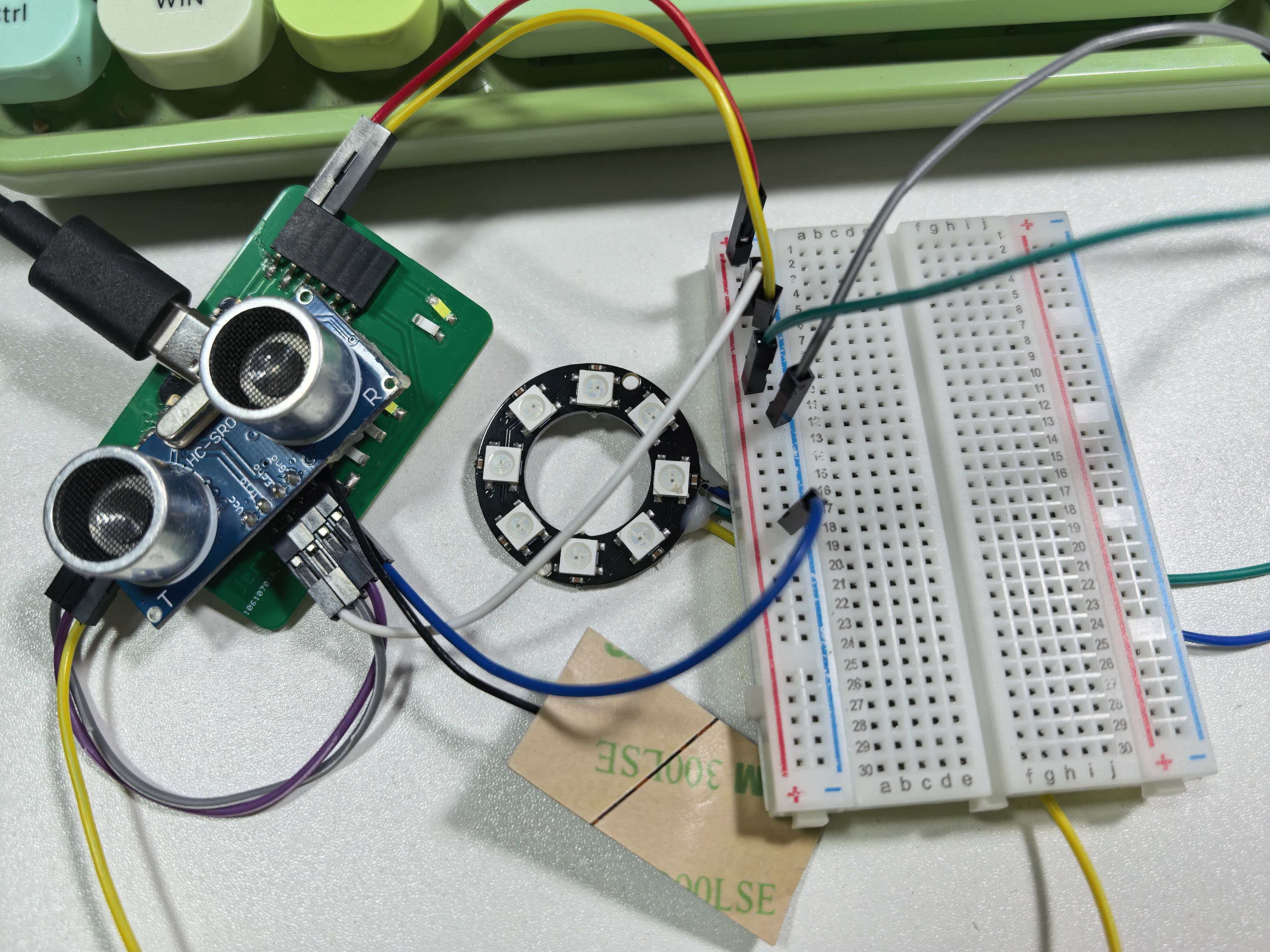
Test setup — HC-SR04 on D1/D2; 8-LED NeoPixel strip on 5V, GND, and D3.
HC-SR04 ultrasonic sensor (input)
| Parameter | Value |
|---|---|
| Operating voltage | 5 V |
| Measuring range | 2 cm – 400 cm (typical) |
| Trigger input | 10 µs HIGH pulse on Trig |
| Echo output | HIGH pulse, width ∝ round-trip time |
| Distance formula | distance (cm) = pulse_duration (µs) × 0.034 / 2 |
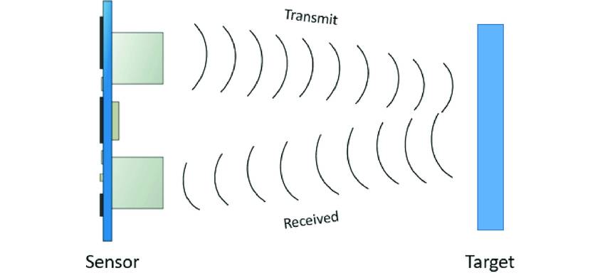
HC-SR04 module — four pins: VCC, Trig, Echo, GND (same sensor as Week 9).
NeoPixel strip (WS2812B) — output
| Parameter | Value |
|---|---|
| Operating voltage | 5 V (use board 5V header, not 3V3) |
| Data protocol | Single-wire serial — 24-bit RGB, ~800 kHz timing |
| Color order | GRB on most WS2812B modules (NEO_GRB) |
| Strip length | 8 pixels on one data line |
| Current per pixel | ~20 mA per channel at full brightness → ~60 mA max (white) |
| GPIO role | Data line only — does not power the LEDs |
Board and wiring
Full board documentation is on the Week 8 page. Both modules share the 5 V and GND rails. Pin assignments:
| HC-SR04 pin | XIAO pin | Notes |
|---|---|---|
| VCC | 5V | Sensor needs 5 V supply |
| GND | GND | Common ground with the board |
| Trig | D1 (GPIO3) | Digital output — sends trigger pulse |
| Echo | D2 (GPIO4) | Digital input — reads echo pulse width |
| NeoPixel pin | XIAO pin | Notes |
|---|---|---|
| VCC | 5V | LED power — NeoPixel needs 5 V |
| GND | GND | Common ground with the board |
| DIN (data in) | D3 (GPIO5) | One-wire serial data from firmware |
I avoided D7/D8/D9 because those are already used by
the on-board button and LEDs. The same pin layout as
Week 9, with NeoPixel data added on D3.
Distance → LEDs lit
| Distance | LEDs lit | Colors shown (LED 0 → last lit) |
|---|---|---|
| ≤ 5 cm (closest) | 8 (all) | Red → orange → yellow → green → cyan → blue → magenta → white |
| ~15 cm | ~6 | Red through blue |
| ~25 cm | ~3 | Red, orange, yellow |
| ~40 cm (farthest in range) | 1 | Red only (LED 0) |
| > 40 cm or out of range | 0 (all off) | — |
Interfacing input and output to the microcontroller
The ESP32-C3 runs two independent interfaces in one loop:
- Input path —
D1sends a 10 µs trigger;pulseIn()onD2captures echo width; firmware averages 5 samples and converts to centimeters. - Output path — measured distance maps to a lit count (0–8); firmware clears the strip, lights LEDs 0…N−1 with palette colors, then calls
show()onD3. - Power — both HC-SR04 and the 8-LED strip draw from the board
5Vrail; with all 8 LEDs on at brightness 50, current is much higher than a single pixel — USB supply may need a bulk capacitor or external 5 V source.
How the Code Works
Firmware: NeoPixelUltrasonic_8LED.ino — builds on UltrasonicRead.ino (Week 9) and drives an 8-LED NeoPixel strip.
- Setup: configures
D1/D2for HC-SR04; initializes an 8-pixel strip onD3at brightness 50. - Read distance: sends a 10 µs trigger, averages 5 echo readings, converts to cm with
duration × 0.0343 / 2. - Map to lit count: ≤ 5 cm → 8 LEDs; 40 cm → 1 LED; out of range → 0 LEDs.
- Update strip: clears all pixels, lights indices 0…N−1 with palette colors, calls
show()only when lit count changes. - Serial feedback: prints distance and number of LEDs lit.
/*
 * NeoPixelUltrasonic_8LED.ino — XIAO ESP32-C3 + HC-SR04 + WS2812B (8 LEDs)
 * Trig -> D1, Echo -> D2, NeoPixel DIN -> D3
 */

#include <Adafruit_NeoPixel.h>

const int trigPin     = D1;
const int echoPin     = D2;
const int neoPixelPin = D3;

#define NUM_PIXELS 8
const float MIN_CM = 5.0;
const float MAX_CM = 40.0;

Adafruit_NeoPixel strip(NUM_PIXELS, neoPixelPin, NEO_GRB + NEO_KHZ800);

const uint32_t palette[NUM_PIXELS] = {
  strip.Color(255,   0,   0),    // red
  strip.Color(255, 128,   0),    // orange
  strip.Color(255, 255,   0),    // yellow
  strip.Color(  0, 255,   0),    // green
  strip.Color(  0, 255, 255),    // cyan
  strip.Color(  0,   0, 255),    // blue
  strip.Color(255,   0, 255),    // magenta
  strip.Color(255, 255, 255)     // white
};

int lastLitCount = -1;

float readAverageDistanceCm() {
  float total = 0;
  int   valid = 0;
  for (int i = 0; i < 5; i++) {
    digitalWrite(trigPin, LOW);
    delayMicroseconds(2);
    digitalWrite(trigPin, HIGH);
    delayMicroseconds(10);
    digitalWrite(trigPin, LOW);
    long duration = pulseIn(echoPin, HIGH, 30000);
    if (duration > 0) {
      total += duration * 0.0343 / 2.0;
      valid++;
    }
    delay(10);
  }
  if (valid == 0) return -1.0;
  return total / valid;
}

int distanceToLitCount(float cm) {
  if (cm < 0 || cm > MAX_CM) return 0;
  if (cm <= MIN_CM)           return NUM_PIXELS;
  return constrain(map((long)(cm * 10), (long)(MIN_CM * 10),
                       (long)(MAX_CM * 10), NUM_PIXELS, 1), 0, NUM_PIXELS);
}

void setup() {
  Serial.begin(115200);
  pinMode(trigPin, OUTPUT);
  pinMode(echoPin, INPUT);
  strip.begin();
  strip.setBrightness(50);
  strip.clear();
  strip.show();
}

void loop() {
  float distance = readAverageDistanceCm();
  int   litCount = distanceToLitCount(distance);

  if (litCount != lastLitCount) {
    strip.clear();
    for (int i = 0; i < litCount; i++) {
      strip.setPixelColor(i, palette[i]);
    }
    strip.show();
    lastLitCount = litCount;
    Serial.print("Distance: ");
    Serial.print(distance, 1);
    Serial.print(" cm -> LEDs lit: ");
    Serial.println(litCount);
  }
  delay(200);
}
Upload settings
- Board:
XIAO_ESP32C3 - Enable USB CDC On Boot
- Library: Adafruit NeoPixel (install via Library Manager)
- Serial Monitor: 115200 baud
Measured results
With my hand 10–30 cm from the HC-SR04, Serial Monitor printed stable lines such as
Distance: 18.4 cm -> LEDs lit: 6. Moving closer increased the lit count;
pulling back reduced it. Beyond ~40 cm or with no reflecting surface, the strip turned off
(LEDs lit: 0).
Problems & Fixes
3V3
gives dim or no output. I confirmed GND was shared between the board and the strip,
and that strip.show() is called after every setPixelColor().
NEO_GRB + NEO_KHZ800 instead of NEO_RGB.
setBrightness(50) and will add a
470 µF capacitor across 5V/GND near the connector on the final lamp PCB.
What I Learned
- NeoPixels are addressable — each LED has an internal controller that decodes a serial data stream and passes the rest downstream.
- The data protocol is timing-critical (~800 kHz); the Adafruit library uses ESP32 RMT hardware so
delay()inloop()does not break the signal. - GPIO supplies the data signal only; LED current comes from the 5 V rail — same lesson as servos, but for lighting.
- Combining Week 9 input with Week 10 output shows how sensor data drives outputs — the same pattern JeLamp uses for gesture → NeoPixel colour.
- An 8-LED strip turns distance into a visible bar graph — easier to read than a single pixel changing color.
strip.clear()before rewriting ensures LEDs beyond the lit count turn off cleanly.- Multimeter group work (VCC = 5.00 V, GPIO ≈ 13.9 mW) confirmed NeoPixel power must be measured on the 5 V rail, not the data pin.
Design Files & Source Code
| File | Description |
|---|---|
| NeoPixelUltrasonic_8LED.ino | Week 10 — HC-SR04 distance → 8-LED NeoPixel bar graph |
| wring.jpeg | Photo — ultrasonic + NeoPixel strip on carrier board |
| wring.png | Wiring diagram |
| UltrasonicRead.ino | Week 9 distance-only test firmware (basis for input code) |
| HelloworldNew.kicad_sch | Board schematic (Week 6/8) |
| HelloworldNew.kicad_pro | KiCad project file |
| HelloWorldWeek8.ino | Week 8 board test firmware |
Hero Shot
My populated XIAO ESP32-C3 carrier board from Week 8, with HC-SR04 as input and an 8-LED WS2812B NeoPixel strip as output — distance controls how many LEDs light up.
Demo — moving hand closer lights more LEDs on the strip.
HelloWorld board — HC-SR04 on D1/D2, 8-LED strip on 5V/GND/D3.