9. Input Devices
This week I interfaced an HC-SR04 ultrasonic distance sensor to my Week 8 XIAO ESP32-C3 board and measured object distance in centimeters. I also participated in the group assignment to probe input signals with an oscilloscope on our populated PCBs, and individually practiced reading an NTC temperature sensor on a breadboard.
Assignment checklist
- Linked to the group assignment page
- Documented what I learned from interfacing an input device to my microcontroller
- Linked to the board I made in a previous assignment
- Explained how my code works
- Explained problems encountered and how I fixed them
- Included original design files and source code
- Included a hero shot of my board
Group Assignment
As a group we used the lab oscilloscope (OWON EDS102 CV) to probe analog levels and digital waveforms on the ESP32 carrier PCBs we designed in Week 6 and fabricated in Week 8. We measured servo PWM pulses and discussed how the same probing method applies to buttons, ultrasonic echo pulses, and other inputs.
Week 9 Group Assignment — Input Devices (Chaihuo Fab Lab)
Oscilloscope — Instrument Parts & Setup
In the lab we used an OWON EDS102CV (100 MHz, 1 GS/s) digital oscilloscope to probe signals on breadboard circuits and populated PCBs. Before measuring a real input, we walked through the main parts of the front panel and how they map to what appears on screen.
| Part / control | Function | What I checked |
|---|---|---|
| CH1 / CH2 BNC inputs | Signal inputs for each channel; probe GND clip must tie to circuit ground | Connected the probe to the sensor output and clipped GND to the breadboard blue rail |
| Volts/Div knobs (CH1, CH2) | Vertical scale — how many volts each grid division represents | Started at 2 V/div for a ~3 V logic-level signal, then zoomed to 50 mV/div for noise |
| Seconds/Div (timebase) | Horizontal scale — how much time each grid division covers | Used 200 ns/div to see high-frequency ripple on a nominally flat line |
| Trigger level & menu | Stabilises repeating waveforms at a chosen voltage crossing | Set DC coupling and adjusted trigger so the trace stopped drifting |
| Run/Stop · Autoset · Measure | Capture control and on-screen readouts (frequency, Vmax, Vmin) | Autoset gave a first guess; Measure panel reported ~552 kHz ripple and 1.6–3.1 V swing |
| Probe compensation (5 V 1 kHz) | Square-wave reference for trimming the probe before real measurements | Verified the probe was compensated so edges were square, not rounded or overshot |
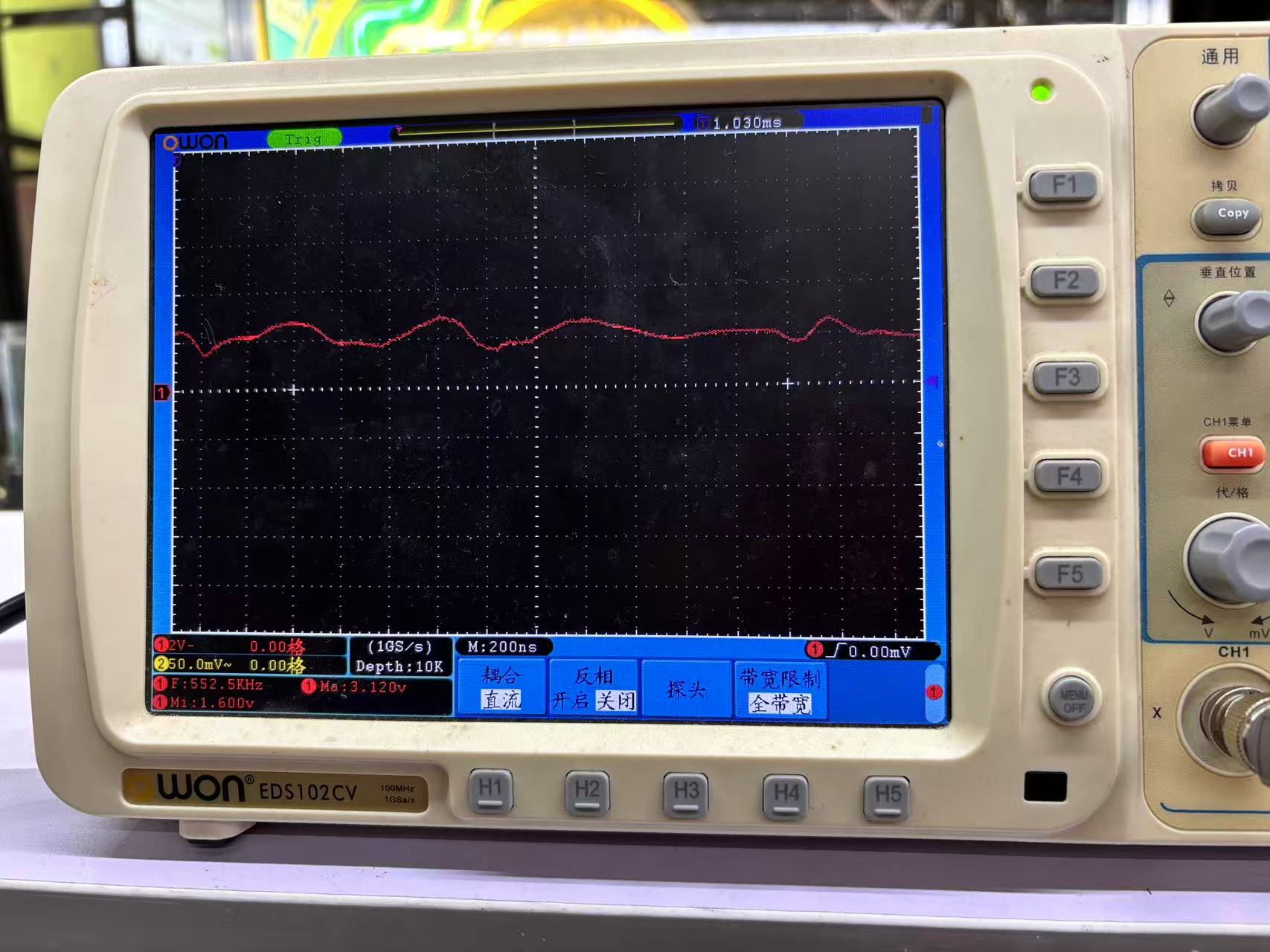
Scope capture: CH1 at 2 V/div, timebase 200 ns — Measure panel shows frequency and Vmax/Vmin.
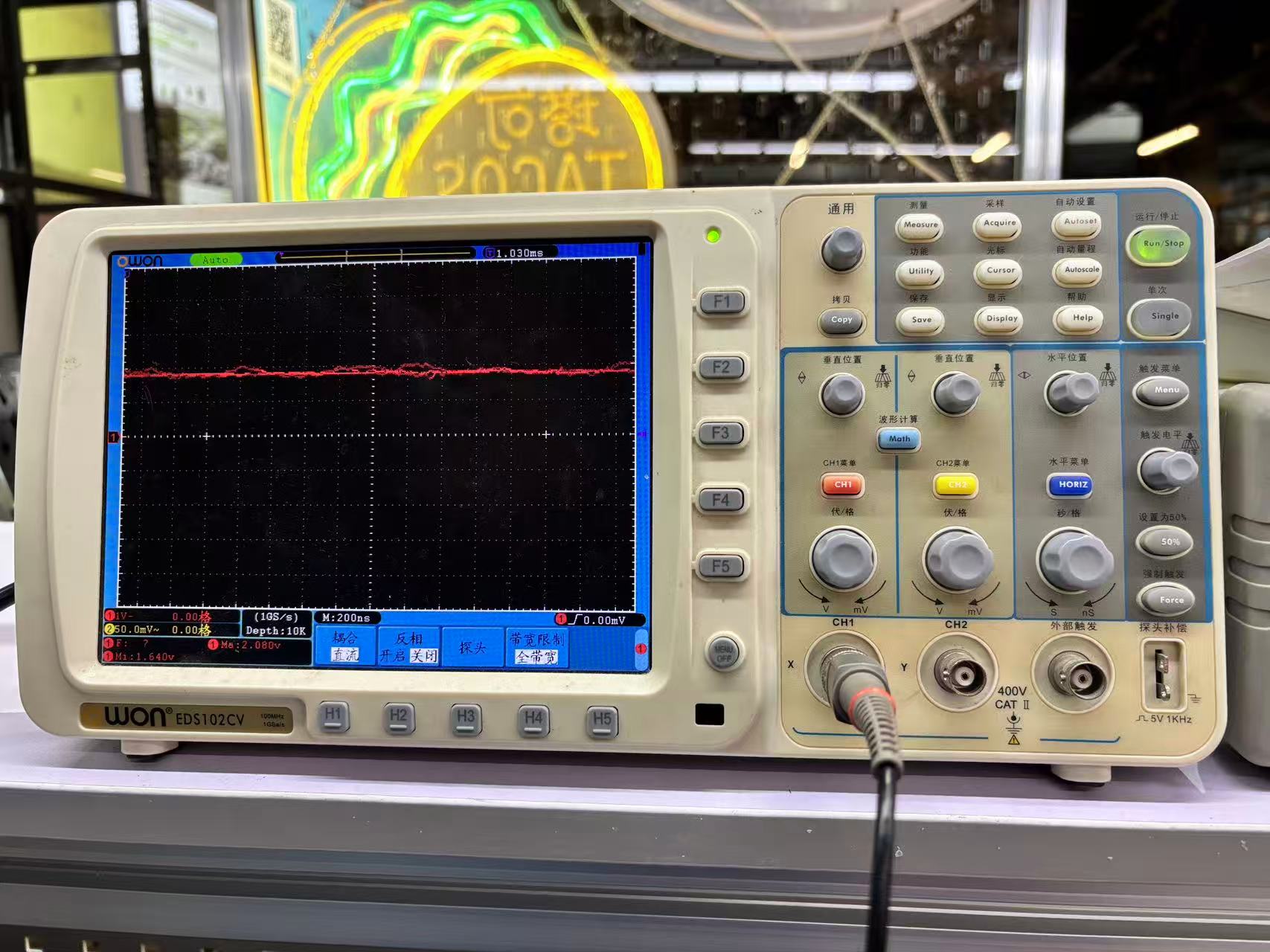
Front panel layout: vertical (CH1/CH2), horizontal (timebase), trigger, and BNC inputs.
Key takeaway: the oscilloscope shows how a signal changes over time, while a multimeter reports a single averaged value. For embedded debugging, I use the scope when I need to see noise, pulse width, or whether a pin is actually toggling — not just whether the voltage "looks right" on a meter.
What I learned from the group work
| Topic | Key takeaway |
|---|---|
| Scope vs. multimeter | The oscilloscope shows signal shape over time; the multimeter gives a steady DC level. Use the right tool for the job. |
| Common ground | Probe GND must connect to the PCB ground plane — floating grounds produce garbage waveforms. |
| PWM as reference | Servo control pulses (~20 ms period, ~1–2 ms width) are a clear digital signal you can see and measure on the scope. |
| Digital pulse inputs | Ultrasonic sensors return a timed echo pulse — the scope shows pulse width, while firmware uses pulseIn() to convert it to distance. |
Individual Learn — NTC Temperature Sensor
During the same group session I individually practiced reading an NTC thermistor module
(labeled NTC R1 on the breakout board) wired to a Seeed Studio XIAO on a breadboard.
The module exposes SIG, NC, VCC, and GND — the thermistor
forms a voltage divider whose output changes with temperature.
I verified the circuit in three steps: confirm supply voltage with the multimeter, probe the analog output with the oscilloscope to see whether the line was stable or noisy, then compare readings as I moved the sensor between my fingers and open air.
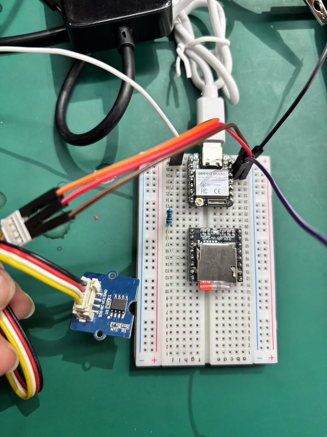
Breadboard setup: XIAO board, NTC R1 module (SIG / VCC / GND), and jumper wiring to the analog input.
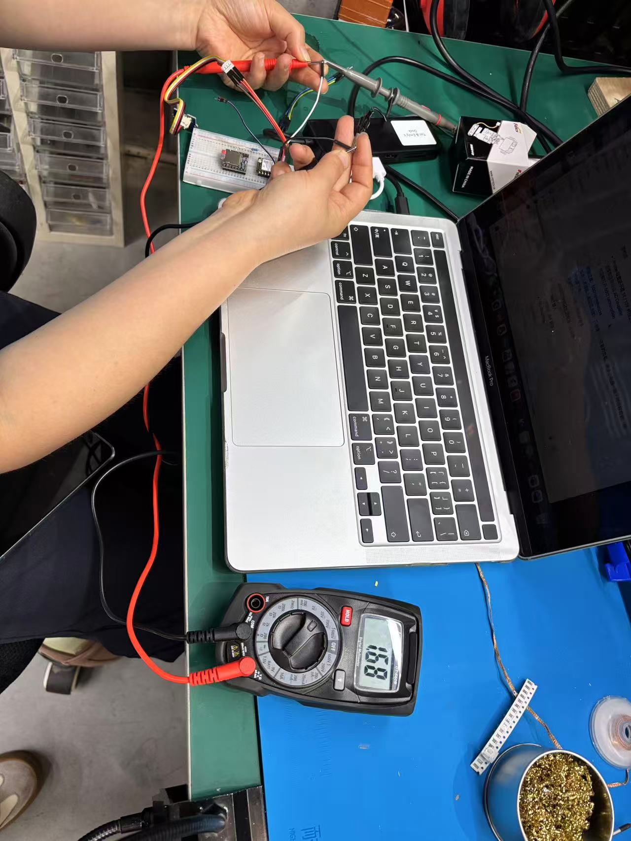
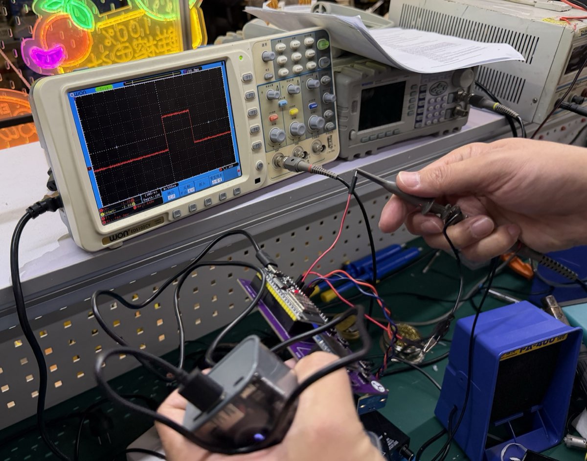
Multimeter reads 16.8 (mV scale) on the sensor node while the scope probe is attached.
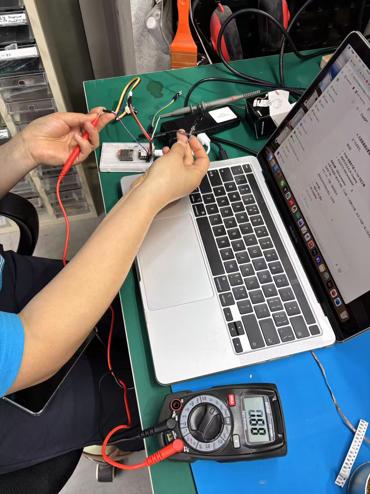
Following the lab probe guide on the laptop — checking coupling and termination before trusting the trace.
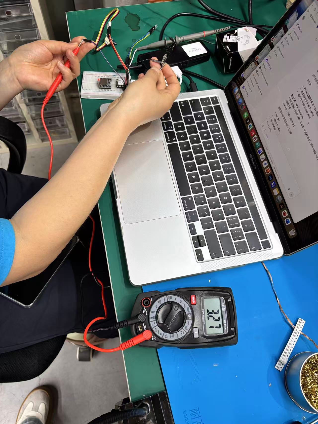
Supply / divider check: multimeter reads 3.27 V on the sensor output pin at room temperature.
What I learned: an NTC sensor does not output a fixed voltage — the divider ratio shifts with temperature, so firmware must either map voltage to °C with a lookup table / Steinhart–Hart equation, or calibrate against a known reference. Measuring with both tools first (meter for DC level, scope for stability) saved me from chasing a software bug when the real issue was a loose GND clip.
Individual Assignment — Measure with a Sensor
Goal: connect an input device to my microcontroller board, read it in firmware, and document the measured values.
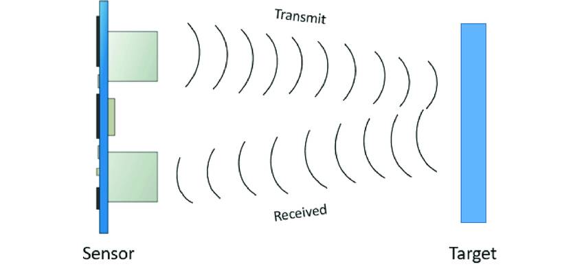
I used an HC-SR04 ultrasonic sensor to measure distance to an object. The module sends a 40 kHz sound burst and listens for the echo. The echo pulse width is proportional to round-trip time; dividing by two and scaling by the speed of sound gives distance in centimeters.
Input test setup — HC-SR04 on 5V, GND, D1 (Trig), and D2 (Echo).
Sensor overview
| Parameter | Value |
|---|---|
| Operating voltage | 5 V |
| Measuring range | 2 cm – 400 cm (typical) |
| Trigger input | 10 µs HIGH pulse on Trig |
| Echo output | HIGH pulse, width ∝ round-trip time |
| Distance formula | distance (cm) = pulse_duration (µs) × 0.034 / 2 |
HC-SR04 module — four pins: VCC, Trig, Echo, GND.
Board and wiring
The carrier PCB was designed in KiCad and manufactured in Week 8 — full documentation is on the Week 8 page. I wired the HC-SR04 to the XIAO header pins:
| HC-SR04 pin | XIAO pin | Notes |
|---|---|---|
| VCC | 5V | Sensor needs 5 V supply |
| GND | GND | Common ground with the board |
| Trig | D1 (GPIO3) | Digital output — sends trigger pulse |
| Echo | D2 (GPIO4) | Digital input — reads echo pulse width |
I chose D1 and D2 to avoid the on-board button (D7) and LEDs
(D8/D9). The echo line outputs 5 V logic; on this test it worked directly on
the ESP32-C3 GPIO, but a resistor voltage divider is safer for long-term use.
HC-SR04 module — four pins: VCC, Trig, Echo, GND.
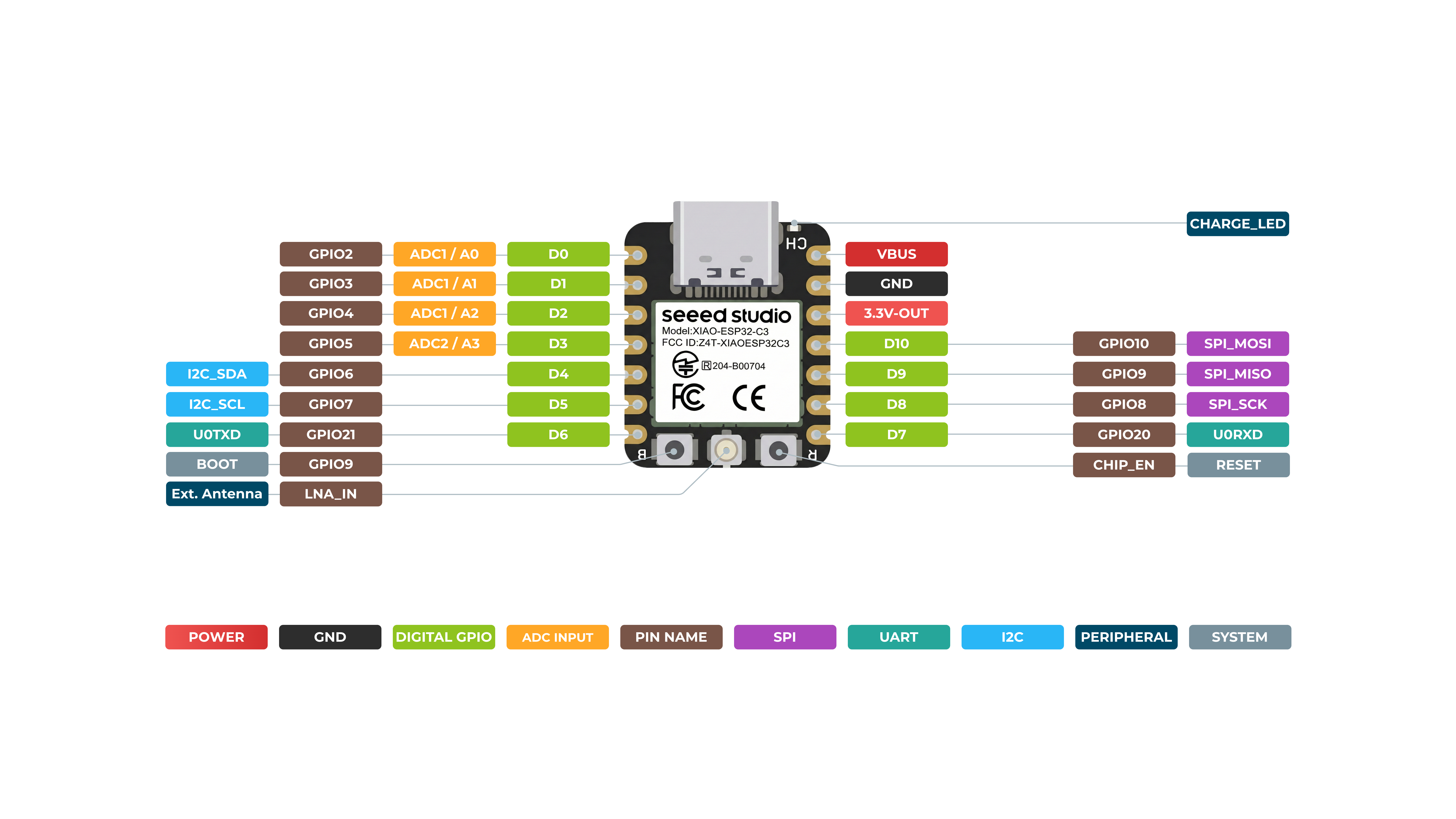
XIAO ESP32-C3 pinout — D1 and D2 used for Trig and Echo.
How the Code Works
Firmware: UltrasonicRead.ino
- Setup: starts USB serial at 115200 baud; configures
D1as output (Trig) andD2as input (Echo). - Trigger: pulls Trig LOW, waits 2 µs, sends a 10 µs HIGH pulse, then returns Trig LOW.
- Measure: uses
pulseIn(echoPin, HIGH, PULSE_TIMEOUT_US)to capture the echo pulse width in microseconds (30 ms timeout ≈ 5 m range). - Convert: applies
duration × 0.034 / 2to get one-way distance in cm. - Average: takes
SAMPLES(5) readings per loop and prints the mean to reduce noise.
/*
 * UltrasonicRead.ino — XIAO ESP32-C3 + HC-SR04
 * Trig -> D1, Echo -> D2
 */

const int trigPin = D1;
const int echoPin = D2;

const unsigned long PULSE_TIMEOUT_US = 30000;  // ~5 m max range
const int SAMPLES = 5;

float readDistanceCm() {
  digitalWrite(trigPin, LOW);
  delayMicroseconds(2);
  digitalWrite(trigPin, HIGH);
  delayMicroseconds(10);
  digitalWrite(trigPin, LOW);

  unsigned long duration = pulseIn(echoPin, HIGH, PULSE_TIMEOUT_US);
  if (duration == 0) return -1.0;
  return duration * 0.034 / 2.0;
}

void setup() {
  Serial.begin(115200);
  pinMode(trigPin, OUTPUT);
  pinMode(echoPin, INPUT);
}

void loop() {
  float sum = 0;
  int valid = 0;
  for (int i = 0; i < SAMPLES; i++) {
    float d = readDistanceCm();
    if (d > 0) { sum += d; valid++; }
    delay(10);
  }
  if (valid == 0) {
    Serial.println("Out of range");
  } else {
    Serial.print("Distance: ");
    Serial.print(sum / valid, 1);
    Serial.println(" cm");
  }
  delay(200);
}
Upload settings
- Board:
XIAO_ESP32C3 - Enable USB CDC On Boot
- Serial Monitor: 115200 baud
Measured results
With the sensor face 10–30 cm from a flat wall, Serial Monitor printed stable lines such as
Distance: 18.4 cm — each value is the mean of five samples. Moving the target
closer or farther updated the reading on the next loop (~200 ms). Targets beyond ~400 cm, or
surfaces too soft to reflect ultrasound, returned Out of range.
Oscilloscope — Trig and Echo Pulses
I probed the HC-SR04 on the oscilloscope while the firmware was running. The
red trace (CH1) shows the Trig pulse — a short HIGH burst sent by
the MCU to start each measurement. The yellow trace (CH2) shows the
Echo line going HIGH for a longer interval; that pulse width is the round-trip time
the firmware reads with pulseIn() and converts to distance.
Seeing both signals on the same timebase made the timing concrete: a narrow trig spike, then a wider echo pulse whose length grows when I moved the target farther away. That confirmed the Serial readings were tracking real ultrasound timing, not a software artifact.
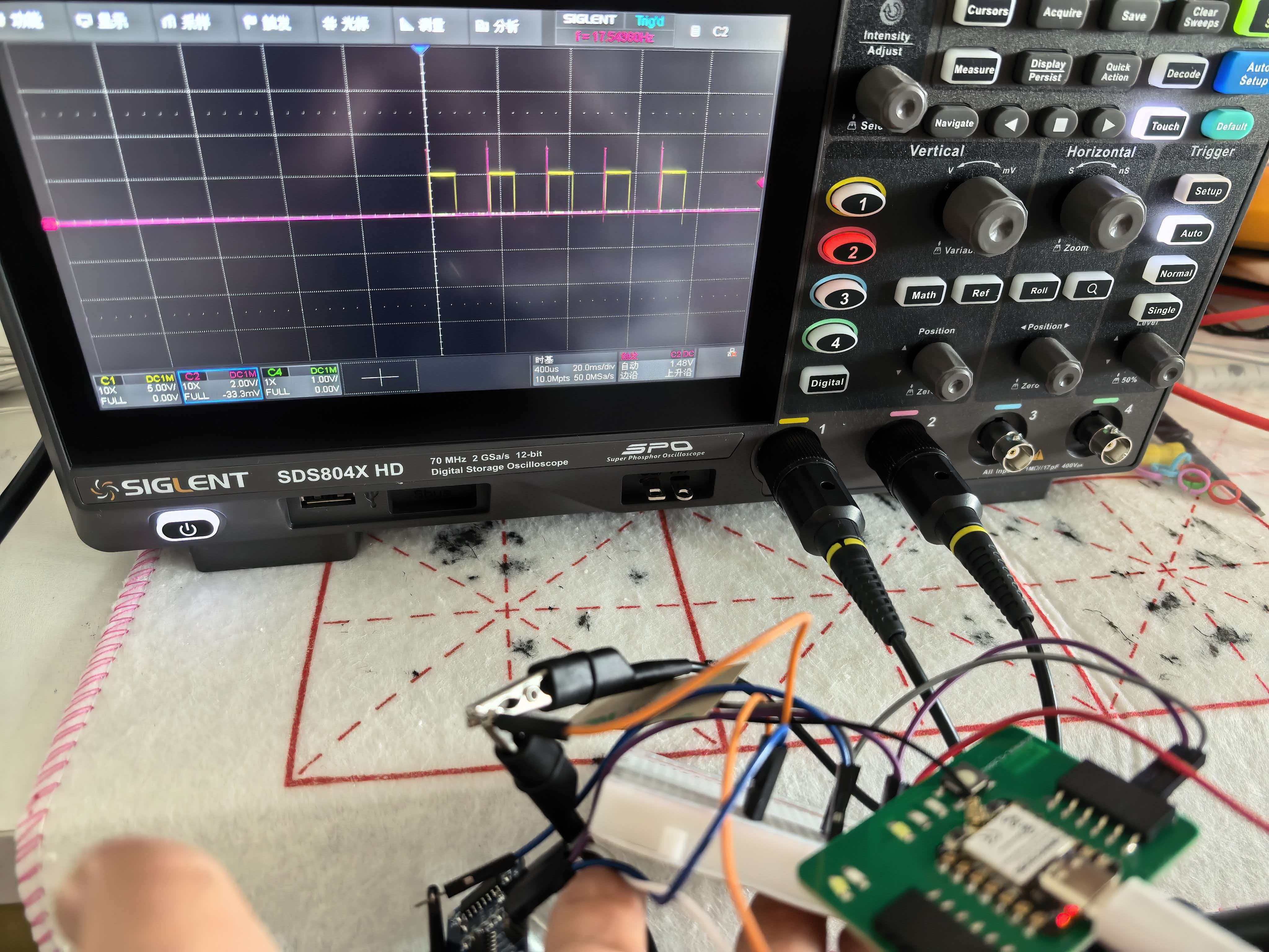
Scope capture on the XIAO carrier board — red (CH1) = Trig pulse, yellow (CH2) = Echo duration. Echo pulse width ∝ round-trip distance.
Problems & Fixes
Out of range even with an object in front of the sensor.
3V3 gives weak or no echo.
I also checked that Trig and Echo were not swapped, and kept the target at least 2 cm from the sensor face.
What I Learned
- How an ultrasonic sensor measures distance via round-trip echo time, not direct voltage.
- How to generate a precise trigger pulse and capture echo width with
pulseIn(). - How to convert pulse duration to physical distance using the speed of sound.
- Why averaging multiple samples reduces noise in time-of-flight measurements.
- From group scope work: an echo pulse is a timed digital input — the scope shows width, firmware converts it to distance.
Design Files & Source Code
| File | Description |
|---|---|
| UltrasonicRead.ino | Week 9 HC-SR04 distance sensor firmware |
Hero Shot
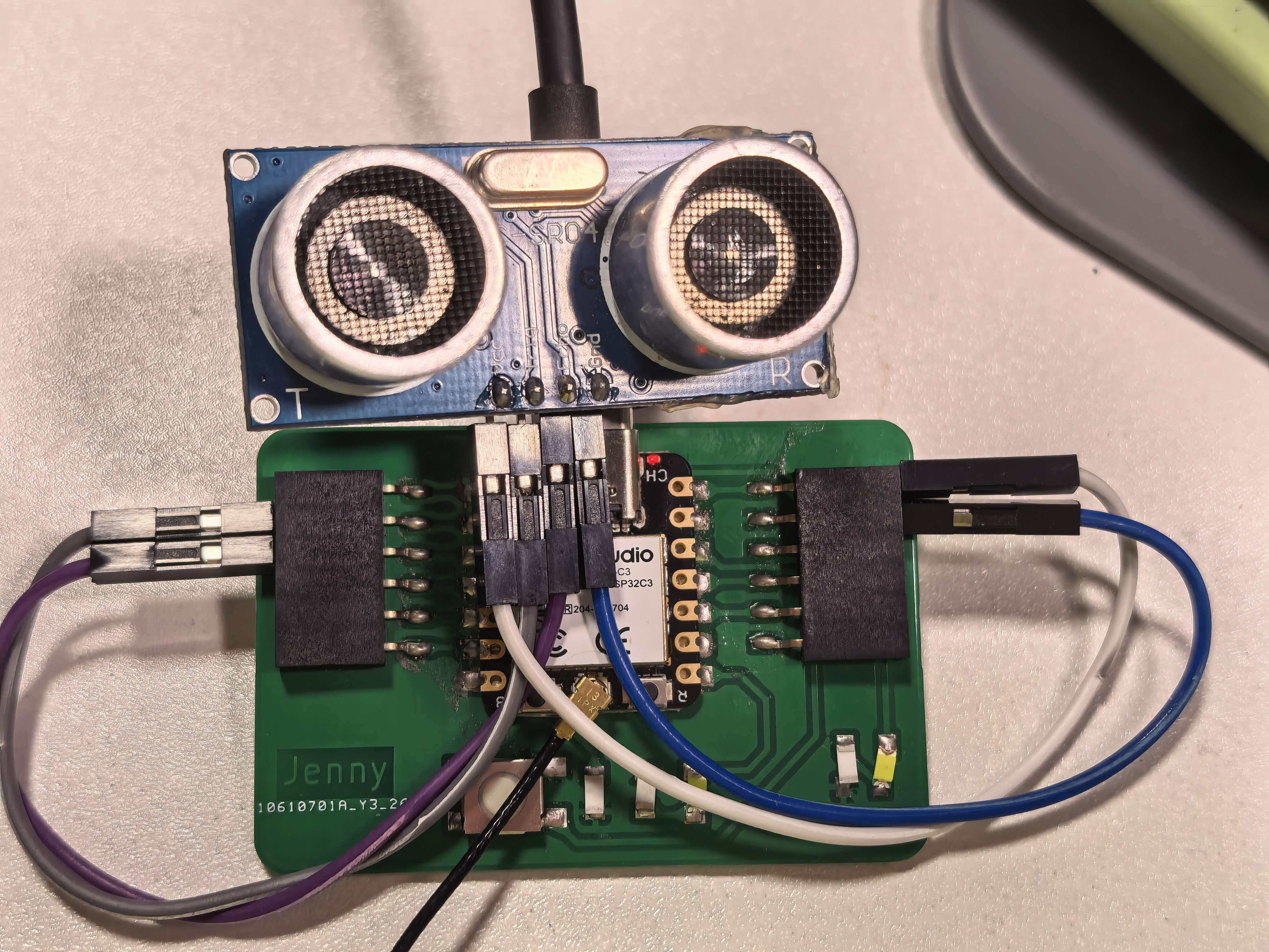
My populated XIAO ESP32-C3 carrier board from Week 8, now used as the platform for this week's ultrasonic distance measurement.
HelloWorld board with HC-SR04 wired to 5V, GND, D1 (Trig), and D2 (Echo) — distance readout on Serial Monitor.