4. Embedded Programming
This week I explored embedded programming using two microcontroller boards — an Arduino Uno (ATmega328P) and an ESP32. I studied their datasheets, wrote firmware for an airflow sensor + NeoPixel strip interaction project, and used Serial output to verify sensor state changes in real time.
Assignment checklist
- Linked to the group assignment page
- Browsed and documented information from a microcontroller datasheet
- Programmed a board to interact and communicate
- Described the programming process(es) used
- Included source code and hero shot(s)
Group Assignment
As part of the group assignment, we compared the programming workflows, tool-chains, and communication interfaces of several microcontroller families available in the lab. Full documentation — including side-by-side comparisons of Arduino, ESP32, and RP2040 — is on the group page:
Week 4 Group Assignment – Embedded Programming (Chaihuo Lab)
Microcontroller Datasheet Research
ATmega328P (Arduino Uno)
The ATmega328P is an 8-bit AVR RISC microcontroller manufactured by Microchip Technology (formerly Atmel). It is the heart of the Arduino Uno and is widely used in maker projects because of its simplicity, good community support, and robust 5 V I/O compatibility.
| Parameter | Value | Notes |
|---|---|---|
| Architecture | 8-bit AVR RISC | Harvard architecture; most instructions execute in 1 clock cycle |
| Max CPU clock | 20 MHz | Arduino Uno runs at 16 MHz with an external crystal |
| Flash memory | 32 KB | 0.5 KB used by bootloader, leaving 31.5 KB for user code |
| SRAM | 2 KB | Stack and heap share this space — tight for string-heavy code |
| EEPROM | 1 KB | Non-volatile; survives power cycles; endurance ≈ 100 000 write cycles |
| Digital I/O pins | 23 | All can source/sink up to 40 mA; 6 support PWM (Timer0/1/2) |
| ADC channels | 6 | 10-bit, successive approximation; reference selectable (AVCC, 1.1 V, external) |
| Communication interfaces | USART, SPI, I²C (TWI) | One of each; USART is shared with USB-Serial bridge on Arduino Uno |
| Operating voltage | 1.8 V – 5.5 V | Arduino Uno board regulates to 5 V |
| Supply current (active) | ≈ 12 mA @ 16 MHz, 5 V | Sleep modes can reduce this to < 1 µA |
Key insight from the datasheet: The ATmega328P has only 2 KB of SRAM. When I first
tried to include large String objects in my Serial debug messages, the program crashed unpredictably.
Switching to Serial.print(F("...")) — which stores string literals in Flash rather than SRAM —
immediately fixed the problem. This is a classic AVR footgun that the datasheet's memory map section
makes clear once you know what to look for.
Datasheet:
ATmega328P-datasheet.pdf
— Microchip ATmega328P datasheet (memory map, electrical characteristics, pinout).
ESP32 (Espressif ESP32-WROOM-32)
The ESP32 is a 32-bit dual-core microcontroller with integrated Wi-Fi and Bluetooth, made by Espressif Systems. Its much larger memory and wireless capabilities make it well-suited for IoT applications.
| Parameter | Value | Notes |
|---|---|---|
| Architecture | Xtensa LX6 dual-core, 32-bit | Two cores can run independently (Arduino IDE uses core 1 by default) |
| Max CPU clock | 240 MHz | 15× faster than Arduino Uno at max frequency |
| Flash (external) | 4 MB (WROOM-32 module) | Connected via SPI; much larger program and asset storage than AVR |
| SRAM | 520 KB | 260× more than ATmega328P — comfortable for JSON parsing, HTTP, etc. |
| Digital I/O pins | 34 (GPIO) | Most support PWM, input-only pins cannot source current |
| ADC channels | 18 | 12-bit SAR; ADC2 channels cannot be used when Wi-Fi is active |
| Wireless | Wi-Fi 802.11 b/g/n + Bluetooth 4.2 / BLE | Both can operate simultaneously |
| Communication interfaces | 3× UART, 2× I²C, 4× SPI, I²S, CAN, Ethernet MAC | Most peripherals are software-mapped to any GPIO |
| Operating voltage | 3.0 V – 3.6 V (I/O) | Not 5 V tolerant! Use level shifters when interfacing with 5 V devices |
Key insight from the datasheet: Unlike the ATmega328P, the ESP32's ADC2 pins are shared with the Wi-Fi radio. I initially tried to read an analogue sensor on GPIO 2 while the Wi-Fi was on and got garbage readings. Moving the sensor wire to an ADC1 pin (GPIO 34) resolved it immediately — a detail buried in the ADC section of the ESP32 Technical Reference Manual.
Datasheet:
esp32_datasheet_en.pdf
— Espressif ESP32 datasheet (ADC, GPIO, wireless, and power specifications).
Programming Process
Tool-chain: Arduino IDE 2
I used Arduino IDE 2 for both boards. The workflow is essentially the same: select the target board in Tools → Board, choose the correct COM / USB port, write the sketch, then click Upload.
- 1 Install board packages – Arduino Uno (AVR core) is built in; for ESP32, I added Espressif's board URL in File → Preferences and installed "esp32 by Espressif Systems" via the Boards Manager.
-
2
Write the sketch – Arduino sketches use a
setup()function that runs once and aloop()function that repeats indefinitely. Both C and C++ features are available. - 3 Compile – The IDE cross-compiles the sketch and links it against the appropriate Arduino core library. The output pane shows flash and SRAM usage, which I checked against the datasheet limits.
- 4 Upload – The compiled binary is uploaded via USB. For the Arduino Uno, the ATmega16U2 USB-to-Serial bridge handles this automatically. For the ESP32, the CP2102 chip provides the same service and also pulses the BOOT/EN pins to enter the bootloader automatically.
- 5 Monitor – I opened the Serial Monitor (Tools → Serial Monitor) at 9600 baud to read debug output and confirm the airflow-triggered color logic was working correctly.
Airflow Sensor Controls NeoPixel Strip Color
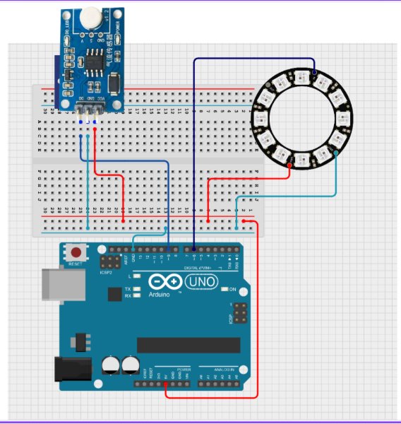
My project uses an airflow sensor as a digital trigger and a NeoPixel strip as visual feedback. The airflow sensor is connected to an Arduino input pin, and the NeoPixel strip is connected to a data output pin. When airflow is detected, the strip changes from yellow to white; when airflow stops, it returns to yellow. I added Serial output to monitor sensor transitions and confirm stable behavior with a short cooldown window.
Code Example
#include <Adafruit_NeoPixel.h>

const int sensorPin = 9;
int lastState = HIGH;
unsigned long lastTriggerTime = 0;
const unsigned long cooldown = 500;

#define PIXEL_PIN 6
#define PIXEL_COUNT 10
Adafruit_NeoPixel pixels(PIXEL_COUNT, PIXEL_PIN, NEO_GRB + NEO_KHZ800);

const uint32_t YELLOW = pixels.Color(255, 255, 0);
const uint32_t WHITE = pixels.Color(255, 255, 255);

void setup() {
  pinMode(sensorPin, INPUT);
  Serial.begin(9600);

  pixels.begin();
  for (int i = 0; i < PIXEL_COUNT; i++) {
    pixels.setPixelColor(i, YELLOW);
  }
  pixels.show();
}

void loop() {
  int currentState = digitalRead(sensorPin);
  Serial.println(currentState);

  if (lastState == HIGH && currentState == LOW) {
    if (millis() - lastTriggerTime > cooldown) {
      Serial.println("Triggered: Switch all to White");
      for (int i = 0; i < PIXEL_COUNT; i++) {
        pixels.setPixelColor(i, WHITE);
      }
      pixels.show();
      lastTriggerTime = millis();
    }
  } else if (currentState == HIGH) {
    for (int i = 0; i < PIXEL_COUNT; i++) {
      pixels.setPixelColor(i, YELLOW);
    }
    pixels.show();
  }

  lastState = currentState;
  delay(10);
}
Hero Shots
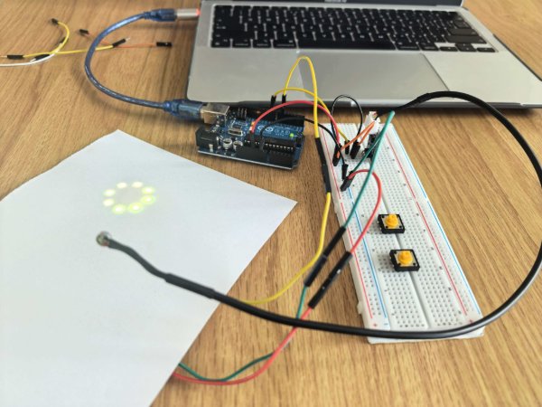
Arduino Uno wired with an airflow sensor and NeoPixel strip, successfully switching strip color based on airflow input.
Demo video: airflow input triggers real-time NeoPixel color change.
Board Interaction & Communication
Both boards communicate with a host computer over UART via USB. The Arduino Uno uses the onboard ATmega16U2 as a USB-to-Serial bridge (virtual COM port at 9600 baud), while the ESP32 dev board uses a Silicon Labs CP2102 chip (115200 baud).
In practice I opened the Arduino IDE Serial Monitor immediately after uploading the sketch. For the airflow + NeoPixel firmware on the Uno, I read sensor state values and trigger messages in sync with blowing on the sensor — confirming that the firmware logic and wiring were correct. For ESP32 work in the lab, I typically use 115200 baud in the Serial Monitor because many ESP32 examples default to that speed; the same USB-UART idea applies for quick debugging.
This simple Serial feedback loop is extremely useful for debugging: rather than relying solely on a logic analyser or oscilloscope, I could trace the program state line-by-line just by reading the monitor output.