5. 3D Scanning and Printing
This week I focused on CAD modeling for additive manufacturing and practiced designing a hinged box in Fusion 360. I also documented the full modeling workflow and design decisions that support reliable 3D printing.
Assignment checklist
- Linked to the group assignment page
- Documented 3D printing design rules from group characterization
- Documented 3D scanning process and results
- Designed and 3D-printed an object (hinged box)
- Included design files and hero shot(s)
Group Assignment Link
The full group assignment documentation is available here: Chaihuo Lab Week 5 Group Assignment .
Personal Reflection on Group Work
In this group assignment, I learned that design-rule testing gives me practical limits before I start modeling real parts. By reviewing overhang, bridging, tolerance, stringing, and diameter behavior from the team tests, I can set clearer expectations for what prints reliably without supports.
One key takeaway for me is that slicer and machine combinations affect small features differently, so I should not assume one profile works for every printer. Comparing results from different setups helped me understand why some details fail even when the CAD model is correct.
For my individual work, I will apply this by adding test-based clearances early, reducing unsupported angles when possible, and planning print orientation before finalizing geometry. This should lower iteration time and make my hinge designs more robust in real fabrication.
Hinged Box Design in Fusion 360
I designed a hinged box as a print-ready model and refined the hinge geometry so the lid and base can move smoothly after printing. The following video and screenshots show my workflow from sketching to final form.
Hinged box modeling demo in Fusion 360.
Modeling steps
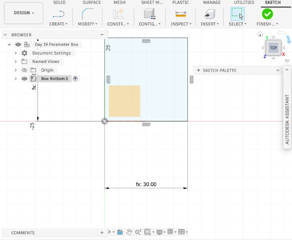
Step 1: In Change Parameters, set BoxWidth = 30 mm, then draw a 30 mm x 30 mm square sketch.
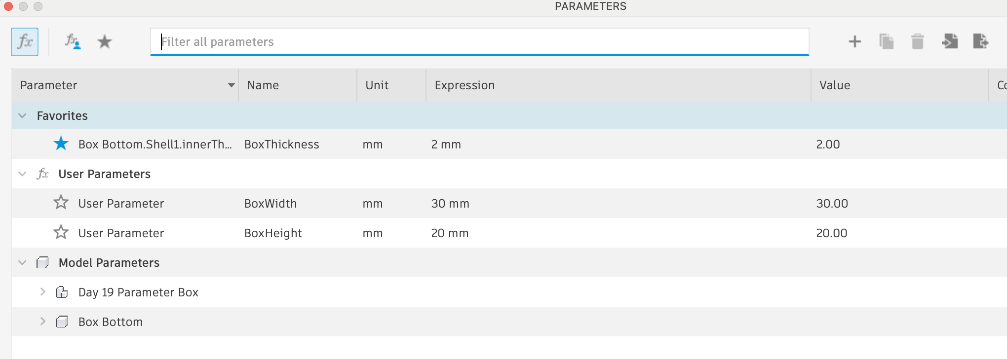
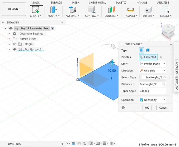
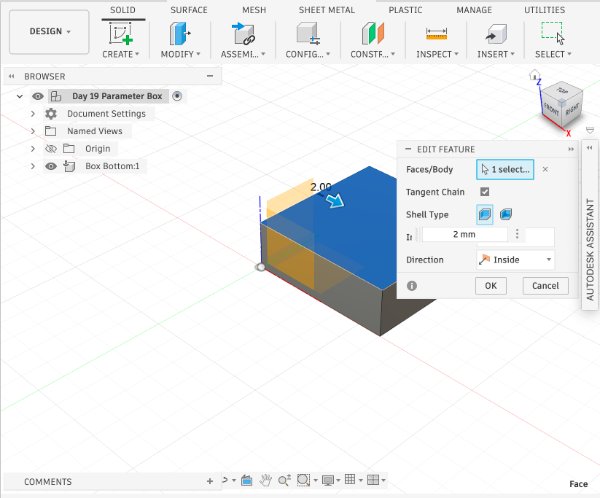
Step 2: Extrude the square to BoxHeight / 2, then apply Shell to hollow the interior volume.
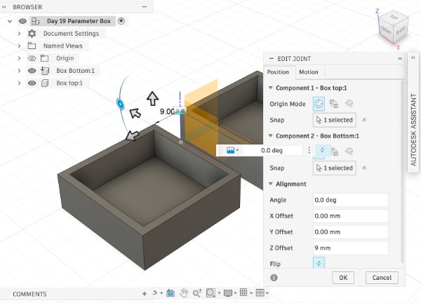
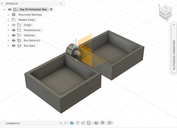
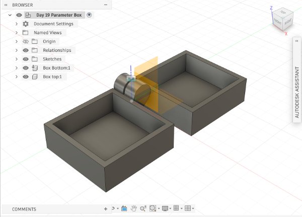
Step 3: Copy the box bottom body and use Paste New to create a separate box top component. Use Joint to place the top above the bottom with a 9 mm offset.
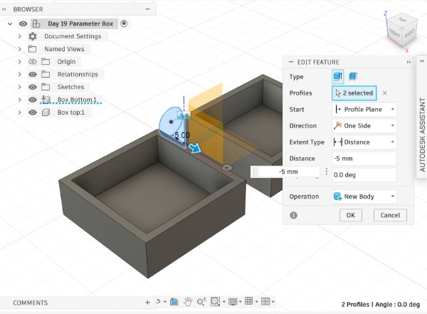
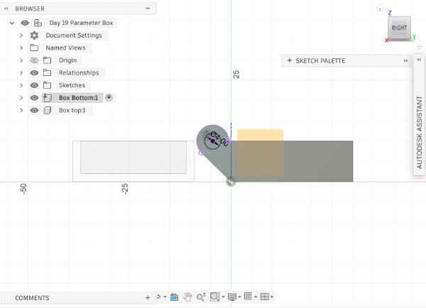
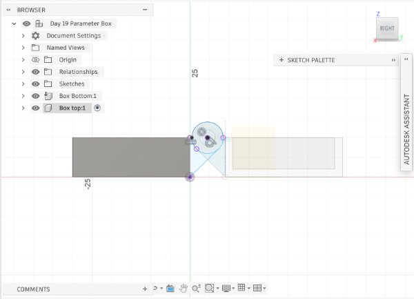
Step 4: Create a sketch on the side face of the box bottom, draw the hinge profile, and extrude it to -5 mm.
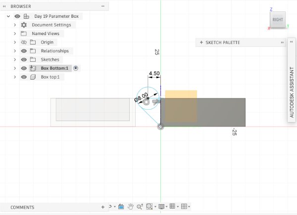
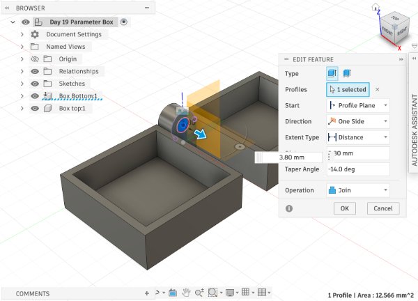
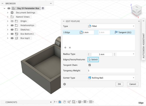
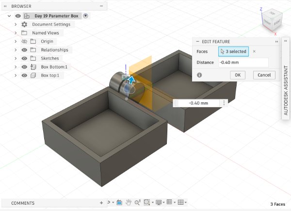
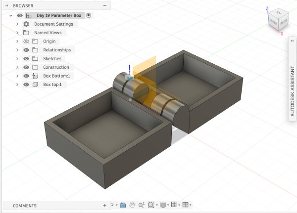
Step 5: Create a sketch on the hinge side face, draw the knob profile, then extrude to 3.8 mm with a taper angle of -14 degrees. Add a 1 mm fillet.
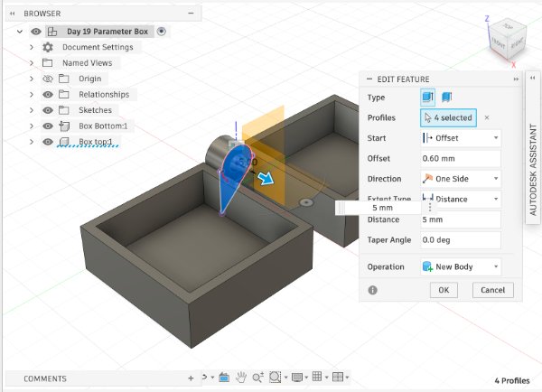
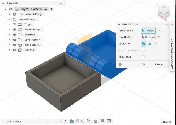
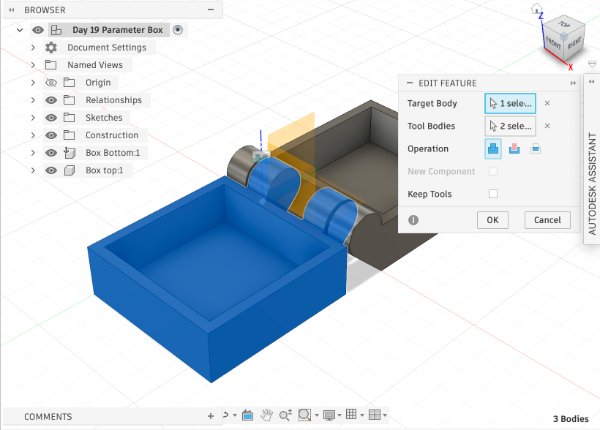
Step 6: Build the inner hinge by sketching on the inside face, projecting the needed edges, and extruding with a 0.6 mm offset. Use Combine to subtract knob-interference regions from the inner hinge.
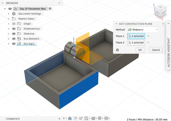
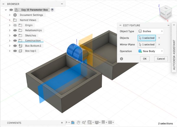
Step 7: After completing one hinge side, mirror the feature set to create the opposite hinge side.
Step 8: Use Joint to assemble the top and bottom components into a functional hinged box.
3D Scanning (Chair) - Detailed Workflow
I used the Revopoint scanner to scan a chair. During the process, I followed the software tracking indicator carefully and moved around the object in a stable path to keep alignment.
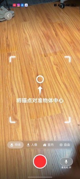
Demo video: scanning a chair with handheld motion.
Step-by-step scanning instructions
- Prepare the scene: place the chair in a clear area with enough walking space around it. Remove nearby moving objects to avoid tracking noise.
- Set stable lighting: use soft, even light. Avoid strong reflections and deep shadows because they reduce feature detection quality.
- Start from a feature-rich area: begin at the seat and backrest corner so the scanner can lock onto clear geometry before you move around.
- Walk slowly and smoothly: keep a constant scanner distance and walk slowly around the chair. Do not swing your arm quickly or change height abruptly.
- Scan in multiple passes: complete one middle-height loop first, then add higher and lower passes to capture top edges, legs, and underside details.
- Handle tracking loss correctly: if tracking is lost, stop immediately, return to a previously captured region, and re-align before continuing.
- Post-process: remove floating noise, trim unwanted mesh, and fill small holes only when needed. Keep important edges sharp for accurate geometry.
- Export for fabrication: export as STL/OBJ, then check mesh scale and orientation before slicing or importing into CAD.
Reflection
My most important lesson this week is that scanning quality depends heavily on movement control. At first I moved too fast, and the model had drift and double surfaces. After I slowed down, kept a fixed distance, and followed a consistent path, the scan result became much cleaner.
The practical rule I will keep using is: walk slowly, move steadily, and scan in planned loops. This approach reduces tracking errors and saves a lot of cleanup time later. In the next iteration, I want to test different chair materials and compare how texture affects scanning accuracy.
In the group assignment, I learned that comparing results across different settings is very helpful. Even small changes in scan path, lighting, or object surface characteristics can strongly affect final mesh quality. Working as a team made it easier to identify repeatable scanning habits and troubleshooting strategies.