3. Computer-controlled cutting
This week, I worked on computer-controlled cutting, focusing on the laser cutter and preparing to work with vinyl cutters. For my assignment, I completed a rounded-rectangle assembly practice exercise and designed a Chinese paper-cut-style box inspired by the famous sculpture "Galloping Horse Treading on a Flying Swallow (马踏飞燕)".
Assignment checklist
- Linked to the group assignment page
- Reflected on laser cutter safety training and characterization
- Completed individual cutting exercises (assembly practice + paper-cut box)
- Documented parametric design and cutting workflow
- Included design files and hero shot(s)
Group assignment
As part of the group assignment, we tested and characterised the Thunder Laser Nova 51 using 3 mm-thick plywood on 5 February 2026. The full test documentation — including focus adjustment, power/speed matrices, kerf measurements, joint clearance tests, and joint-type samples — is recorded on the group page:
Personal reflections
This week was my first time systematically characterising a laser cutter rather than simply using one, and it reshaped how I think about the machine.
The most surprising takeaway was how tightly all the parameters are coupled. I had assumed I could independently increase speed to save time, but a higher speed with unchanged power left the cut incomplete, while reducing speed too far caused excessive charring that actually weakened the wood fibres. Finding the 65% power / 15 mm/s sweet spot required running the full test matrix — there was no shortcut.
Measuring the kerf (≈ 0.15 mm per side) was equally eye-opening. Before this exercise, I had been designing finger joints using the nominal material thickness, then spending extra time sanding or re-cutting to get parts to fit. Now I understand that a 3 mm slot needs to be drawn as 3.0–3.1 mm in the file to account for the material already removed by the beam, and I can dial this in precisely rather than guessing.
The safety training reinforced habits that I want to carry into every future session: never walk away from a running job, always confirm the extraction fan is on before hitting start, and double-check the material. I was not previously aware that certain composite plywoods can contain formaldehyde-heavy glues that produce particularly harmful smoke.
Safety training
Before operating the laser cutter, I completed the lab's safety training, which covered the following key points:
- Never leave the machine unattended while it is running — fire hazards can develop within seconds.
- Always keep the fume extraction system on to prevent inhaling toxic smoke, especially when cutting plywood or acrylic.
- Check the material first — PVC and chlorine-containing materials are strictly forbidden because they release corrosive and toxic gases.
- Know the emergency stop — the big red button on the machine immediately halts the laser and the motion system.
- Keep the lid closed during cutting; the Thunder Laser Nova 51 has an interlock that pauses the job if the lid is opened.
- Fire extinguisher location — a CO₂ extinguisher is mounted next to the machine; never use a water extinguisher near electrical equipment.
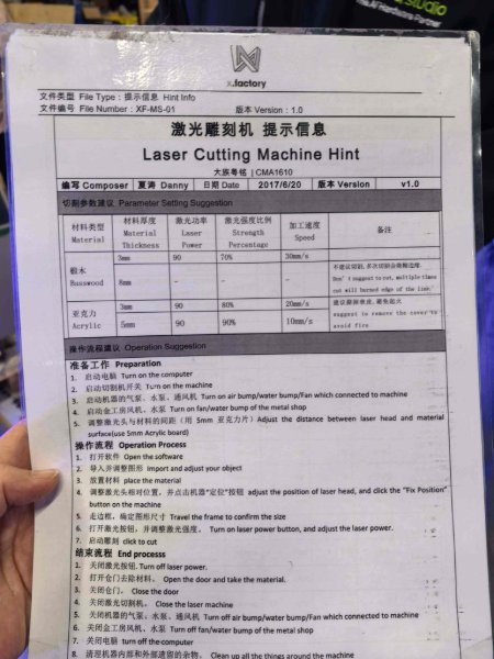
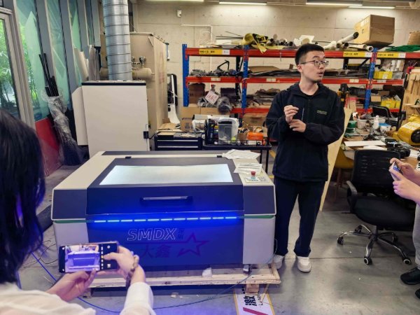
Laser cutter characterisation – Thunder Laser Nova 51
The tests below were performed on 3 mm plywood with the Thunder Laser Nova 51 (CO₂ laser, 100 W rated power).
Focus
The Nova 51 uses a fixed-focus lens with a focal length of 50.8 mm (2 in). Focus is set by placing the provided acrylic focus gauge between the nozzle tip and the material surface, then locking the Z-axis at that height. Proper focus produces the smallest, most intense spot, giving clean cut edges and minimising char.
Power, speed and rate (test matrix)
We ran a grid of test squares to find the optimal cutting parameters for 3 mm plywood. The table summarises selected results:
| Operation | Power (%) | Speed (mm/s) | Passes | Result |
|---|---|---|---|---|
| Vector cut | 70 | 20 | 1 | Clean cut, slight char on edge |
| Vector cut | 65 | 15 | 1 | Best result – clean cut, minimal char |
| Raster engrave | 25 | 300 | 1 | Light surface marking |
| Raster engrave | 40 | 200 | 1 | Best result – clear, even engraving depth |
The rate parameter (scan-line interval / DPI for raster, or pulse frequency for vector) was kept at the LaserMaker default of 500 DPI / ~20 kHz, which produced consistent results for both engraving and cutting on this material.
Kerf
We measured the kerf by cutting a 100 mm × 100 mm square and measuring both the cut-out piece and the remaining hole with digital calipers. The difference, divided by two (one side each), gave a kerf of approximately 0.15 mm per side (≈ 0.30 mm total beam width) at the optimal cutting settings above. This value was used to offset paths in subsequent designs.
Joint clearance
To find the correct press-fit clearance, we cut a series of finger-joint test pieces with slot widths ranging from 2.9 mm to 3.2 mm (in 0.1 mm steps) for a nominal 3 mm material thickness. The tightest friction fit without needing a mallet was achieved at a slot width of 3.0 mm, corresponding to a clearance of 0.0 mm offset (kerf alone provides the necessary play). A slot width of 3.1 mm gave a looser but still solid glue-ready fit.
Joint types tested
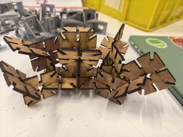
- Finger / box joints – used for the six-sided box; strong and self-aligning.
- T-slot joints – useful for perpendicular connections without glue.
- Living hinges – thin kerf patterns that allow the plywood to flex; requires careful power/speed tuning so the thin bridges survive.
- Press-fit slots – simple slot-and-tab connections; quick to design and assemble.
Laser cutting workflow
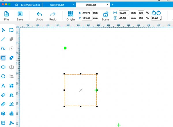
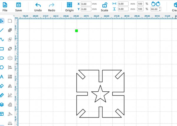
Individual exercise 1: rounded-rectangle assembly practice
Before starting my final decorative panel, I made a small fitting exercise in LaserMaker to validate slot sizing and array operations.
Parametric design using Fusion 360
-
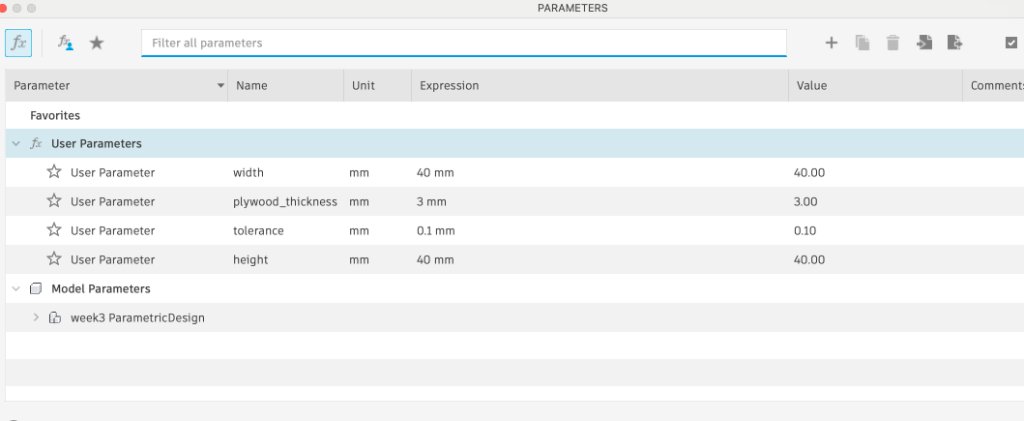
Create a new sketch and open the Parameters dialog. Add user parameters for
width and height (40 mm each), plywood_thickness
(3 mm), and tolerance (0.1 mm).
-
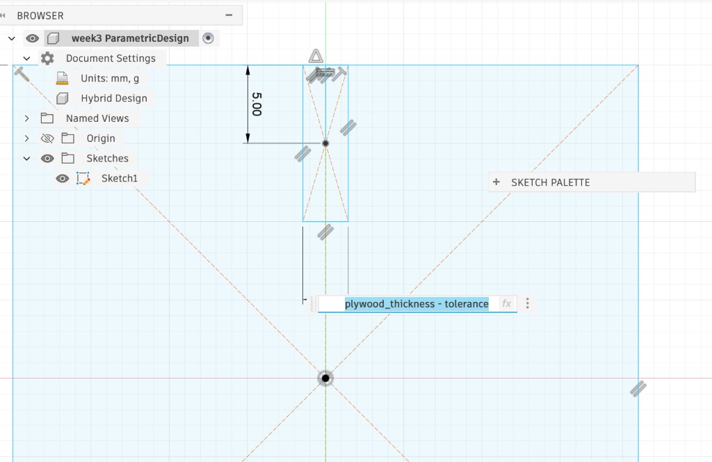
Draw a rounded rectangle with both dimensions linked to the width and
height parameters. Then sketch a slot rectangle with width set to
plywood_thickness - tolerance so joint clearance updates automatically when
the material thickness changes.
-
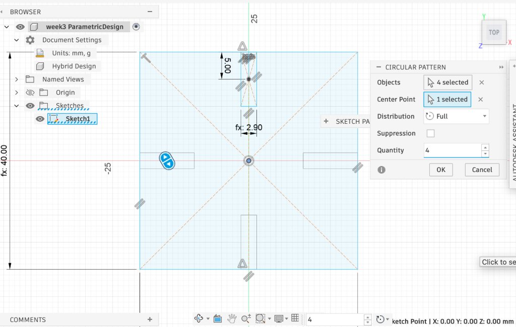
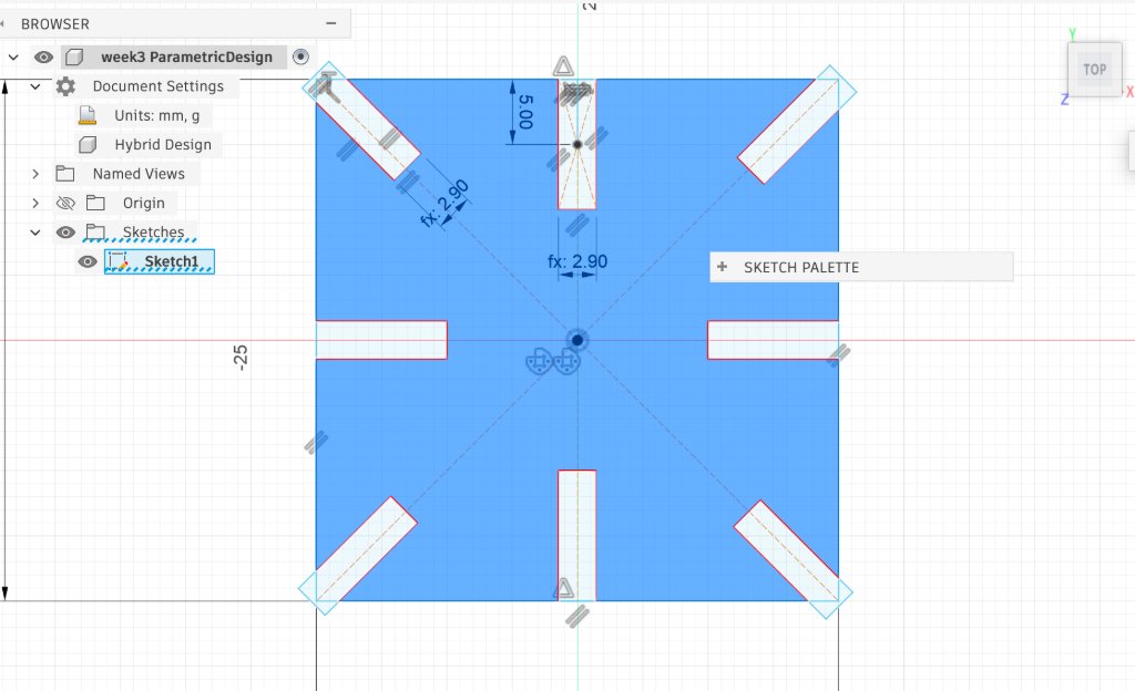
Select the slot geometry and use the Circular Pattern tool with the sketch origin
as the centre point, quantity 4, and full 360° distribution to
place slots around the panel.
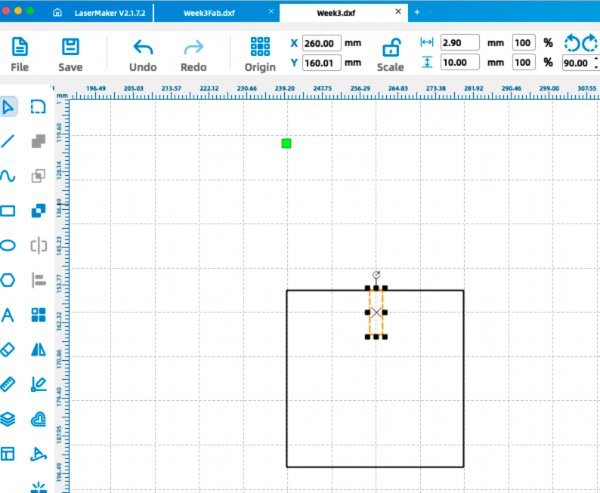
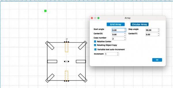
LaserMaker: rounded-rectangle assembly practice
-
Draw a rounded rectangle with both width and height set to 40 mm.
-
Draw a second rectangle with width 2.9 mm (for clearance testing) and length 10 mm.
-
Copy the slot rectangle and use the circular array feature with a step angle of 90°.
-
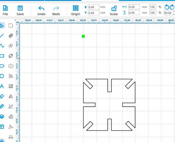
Use the difference operation to subtract the slot geometry from the rounded rectangle.
-
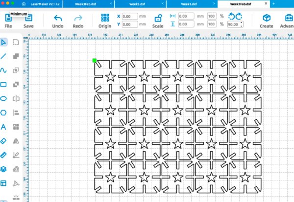
Add a five-point star at the center as an internal decorative element, then use the array feature to generate row and column copies.
-
Export the file as a
.dxf, load it into the laser software, and set the cutting parameters (power and speed) according to the tested profile.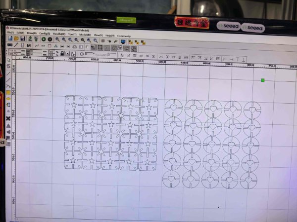
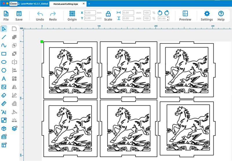
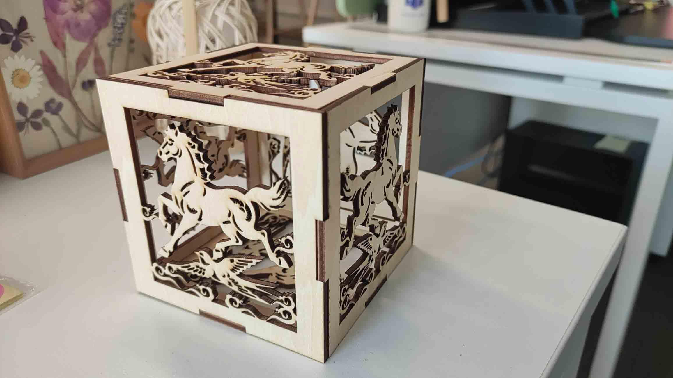
Individual exercise 2: paper-cut box panel
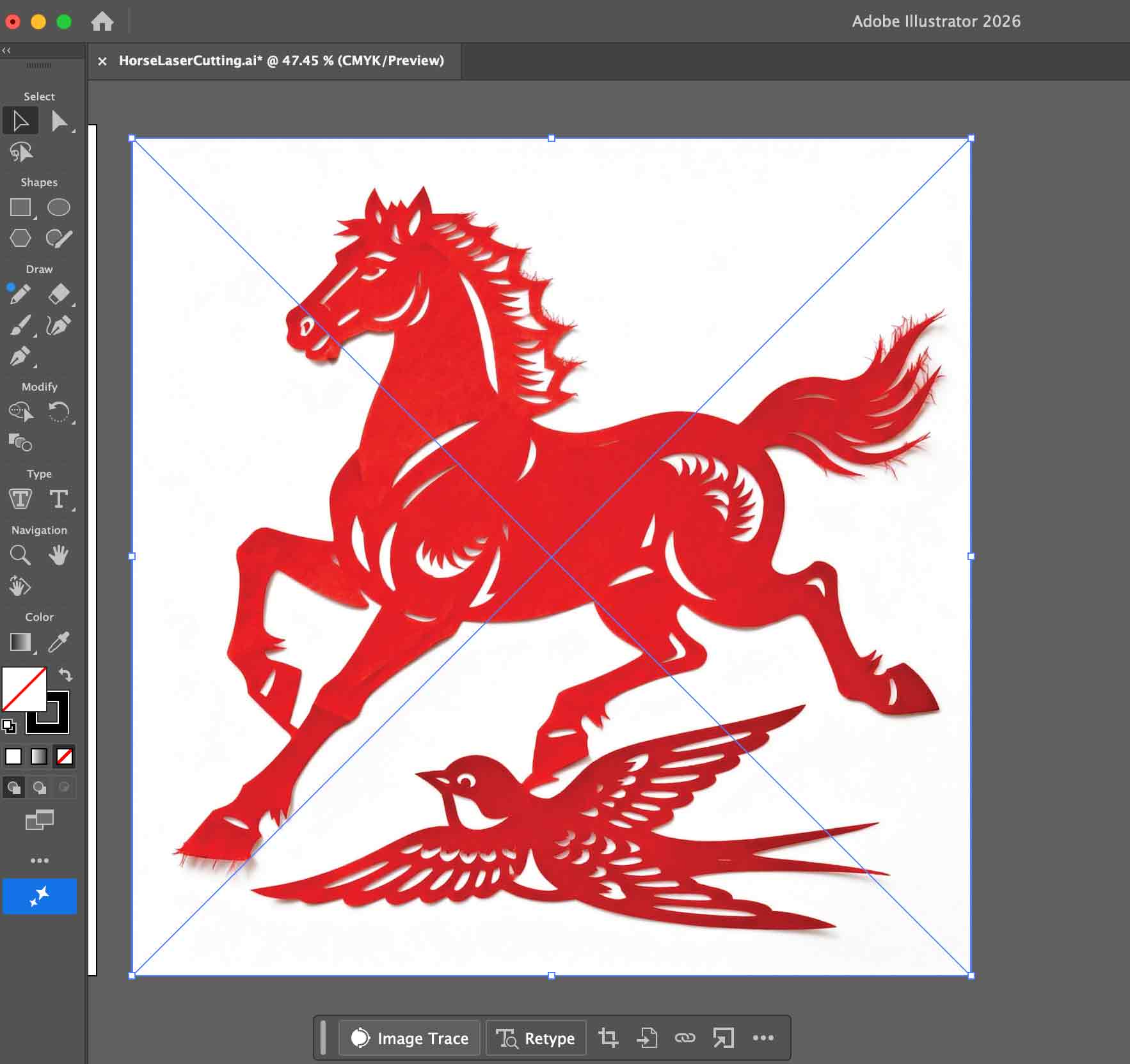
For my main individual exercise, I designed a laser-cut box panel in Chinese paper-cut style, based on the famous sculpture "Galloping Horse Treading on a Flying Swallow (马踏飞燕)". I applied the week's characterisation results directly: kerf offsets in Illustrator and the validated power/speed profile in LaserMaker. On the first full-scale cut, the internal bridges stayed intact and the box joints assembled cleanly, with no fit-up rework needed.
- AI-generated paper-cut design: I used Jimeng AI to generate a Chinese paper-cut-themed design based on the famous sculpture "Galloping Horse Treading on a Flying Swallow (马踏飞燕)". This gave me a high-contrast image suitable for vectorisation and laser cutting.
-
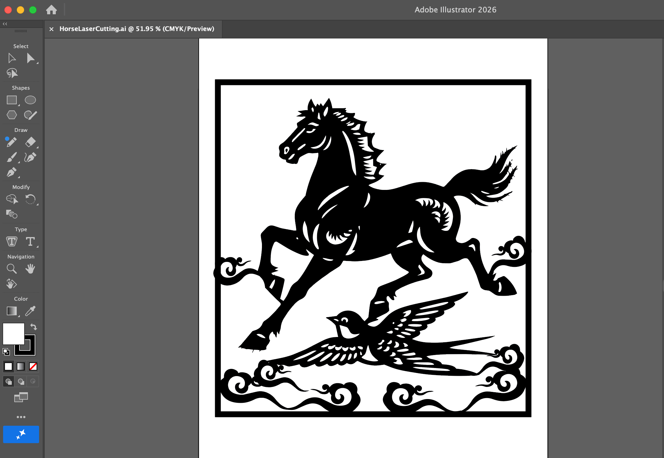
Vectorising the design in Illustrator:
I imported the image into Adobe Illustrator and used the Image Trace tool to convert it into vector paths.
I then refined the curves and simplified the shapes so that the design would cut cleanly on the laser cutter.
-
Ensuring structural connectivity for laser cutting:
I carefully adjusted the paths so that the horse, swallow, and decorative details were all structurally
connected to the outer frame. This prevents any isolated pieces from falling out after cutting and makes the
whole design behave like a single, continuous paper-cut.
-
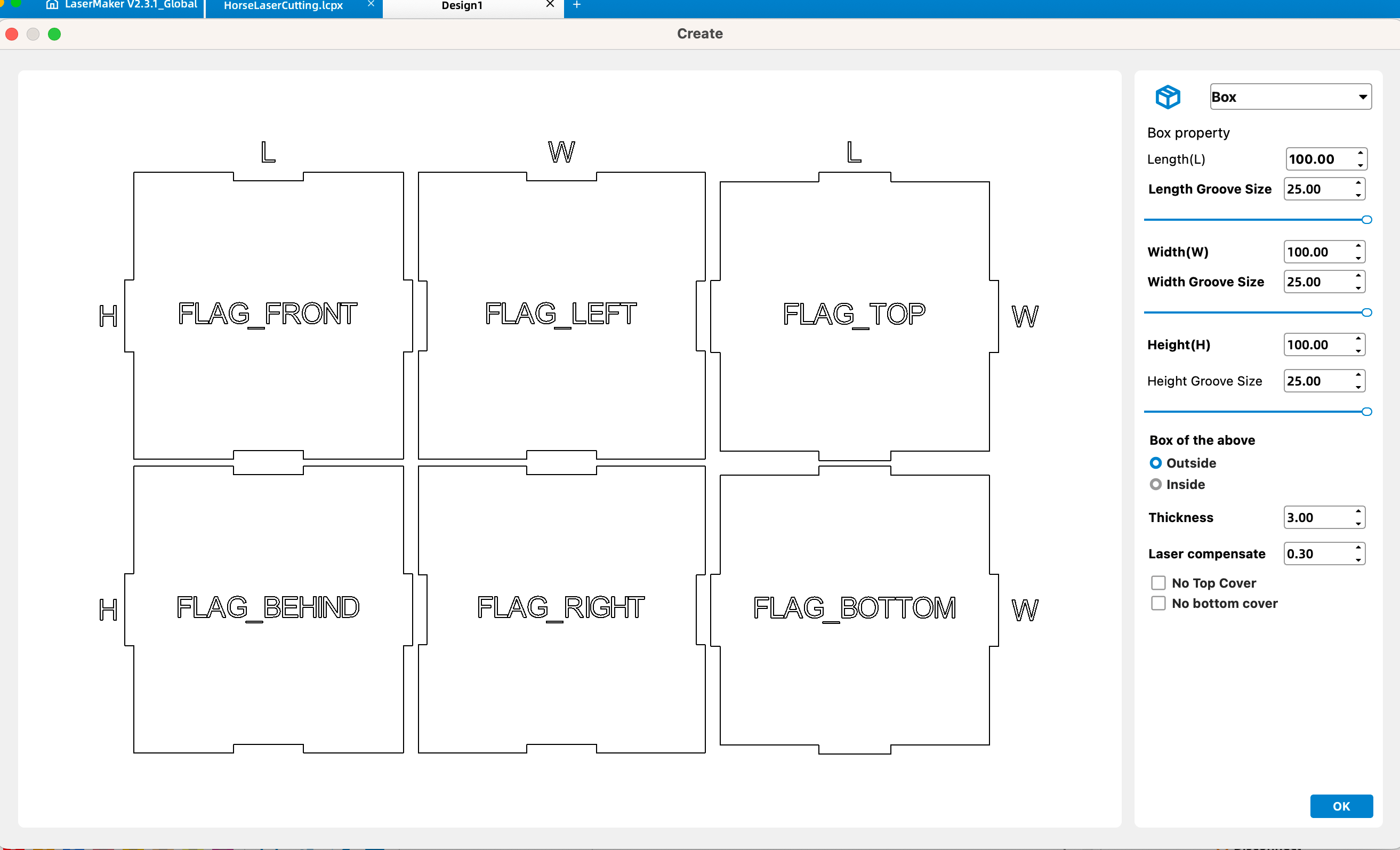
Designing the six-sided box:
Using LaserMaker's box-making feature, I generated a six-sided box and tuned the length, width, height, and
joint parameters so the paper-cut panel could be integrated into one side of the box while keeping the
overall structure easy to assemble.
-
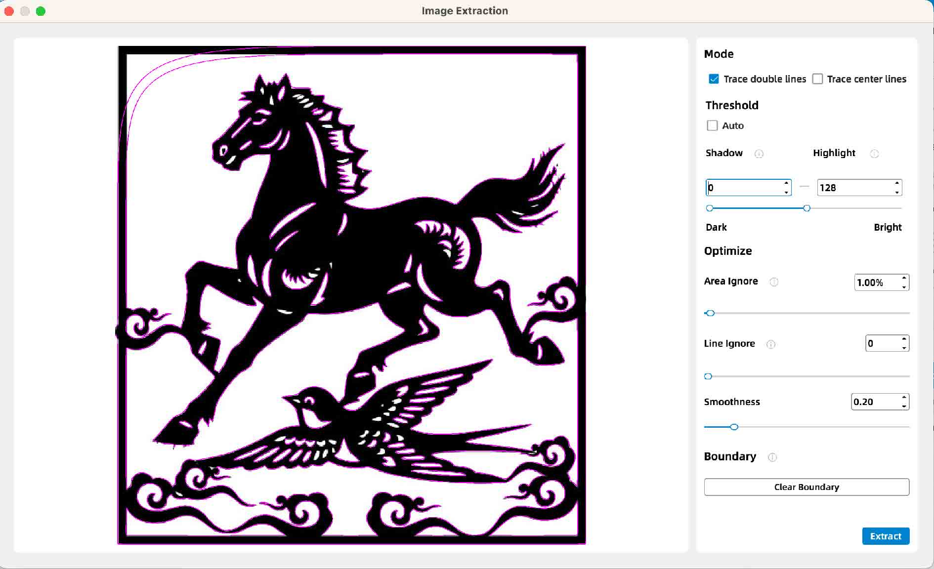
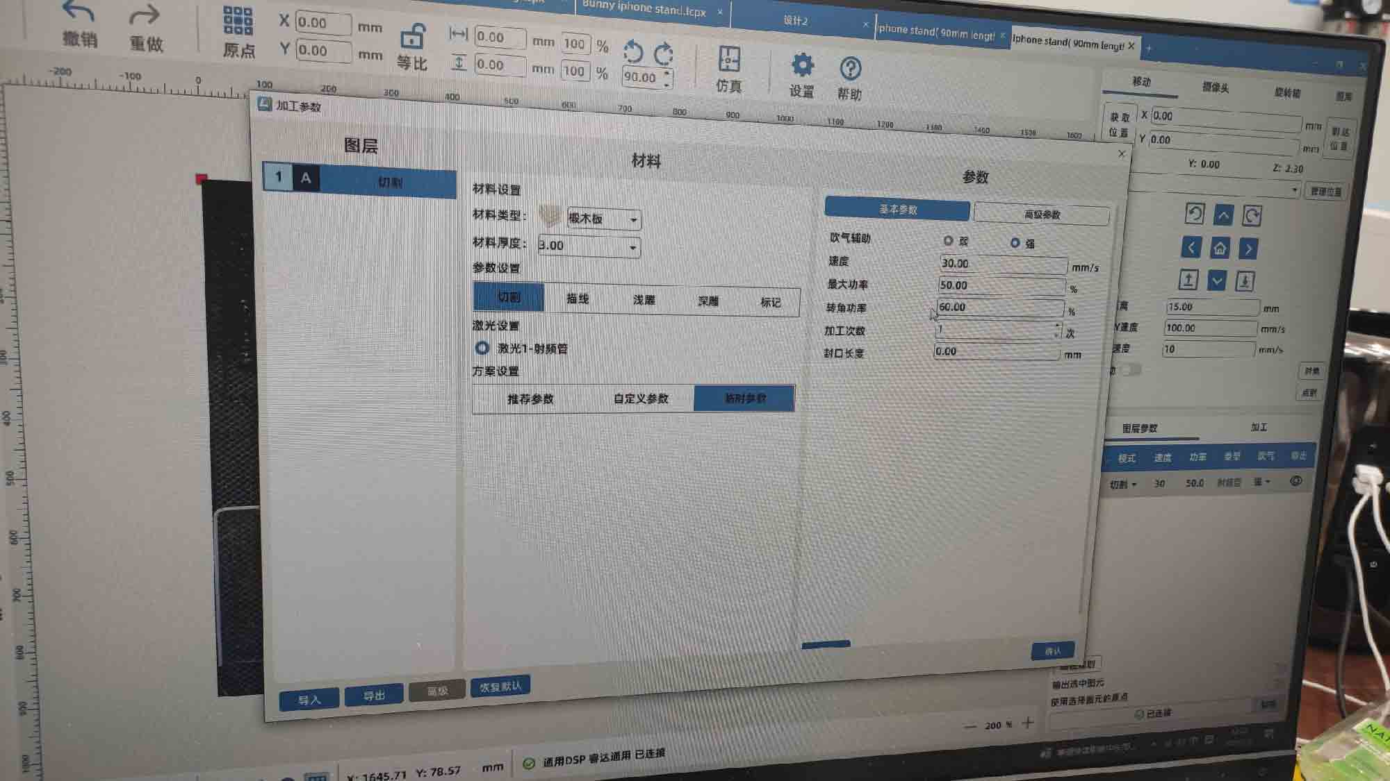
Preparing cutting paths in LaserMaker:
I imported the cleaned vector file into LaserMaker, extracted the outlines as cutting paths, and adjusted the
routing settings (power, speed, and pass count) according to the material thickness and the laser cutter's
capabilities.
-
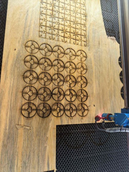
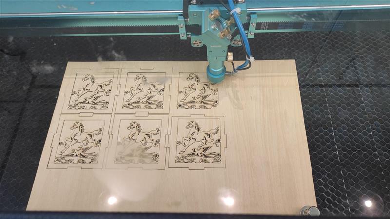
Cutting the design on the laser cutter:
I set the laser cutter to cutting mode and started the cutting process.
-
Final result:
The final result is a paper-cut box depicting the famous sculpture
"Galloping Horse Treading on a Flying Swallow (马踏飞燕)".
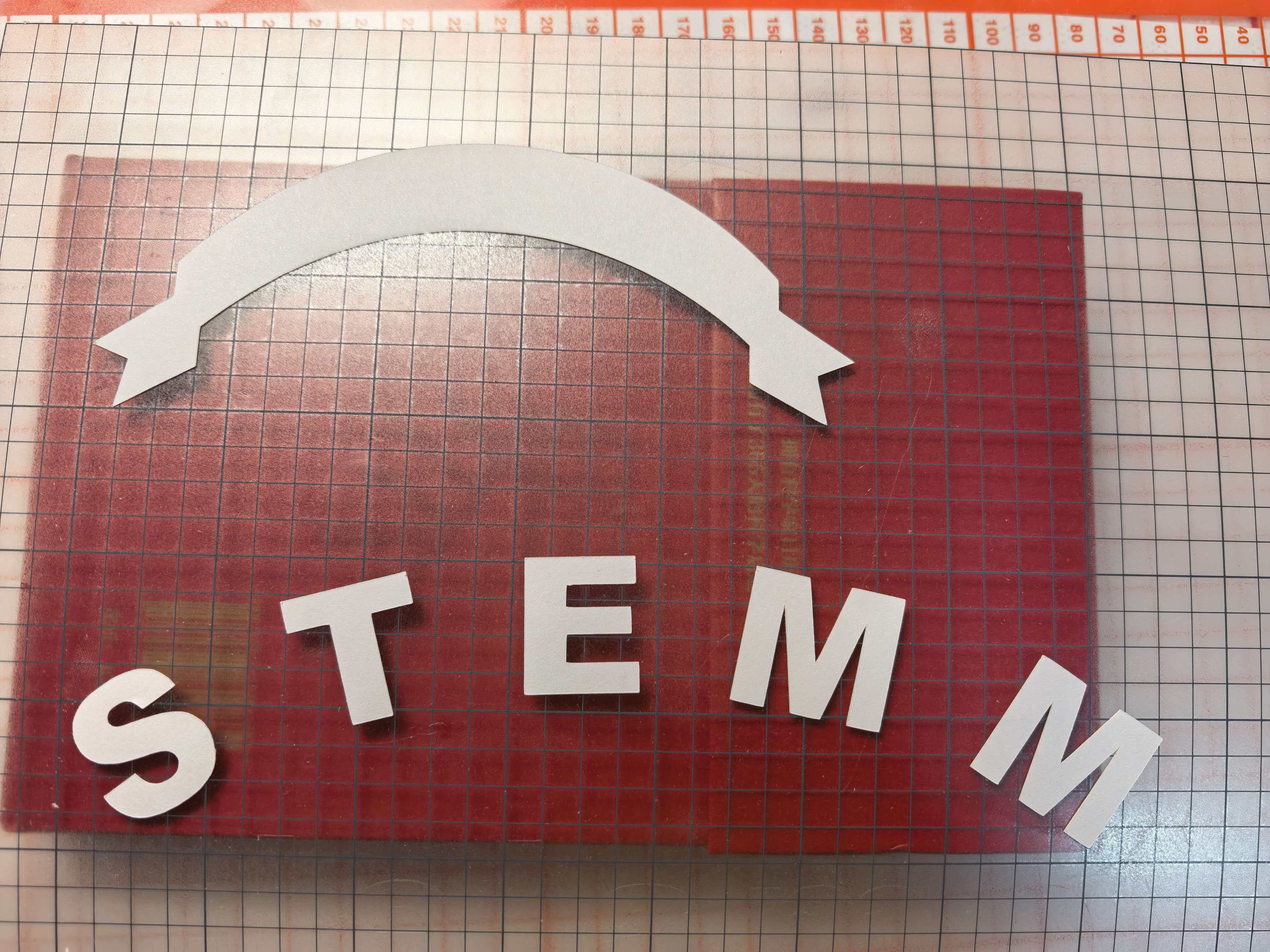
Vinyl cutting
After the laser exercises, I designed a small arched banner logo in Adobe Illustrator and cut it on the lab's Silhouette CAMEO 5 vinyl cutter using white sticker paper. The workflow below covers vector drawing, text layout, path cleanup, and send-to-cut settings in Silhouette Studio.
Adobe Illustrator — arched banner logo
-
Draw the ribbon outline:
Create a new document and use the Curvature Tool to sketch the top arc of the banner.
Switch to the Pen Tool to close the shape with straight segments and add the swallowtail
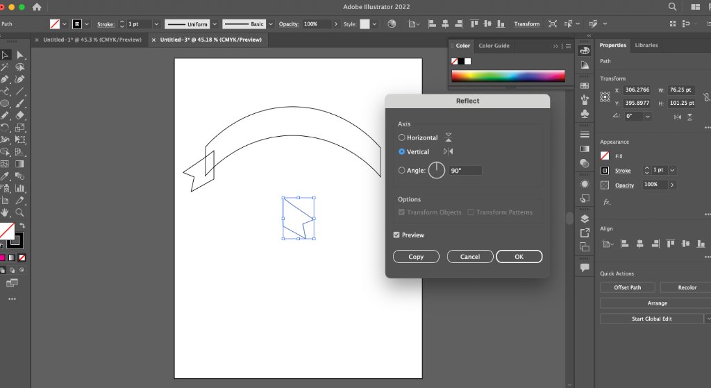
notches at each end. Copy the finished end piece, paste a duplicate, and use
Object → Transform → Reflect (vertical axis) to mirror it for the opposite side.
- Add curved text: Type the label with the Type Tool, then use Type on a Path (or the Vertical Type on a Path option) to follow the inner arc of the banner. Adjust tracking and baseline offset until the letters sit evenly inside the ribbon.
-
Merge paths for cutting:
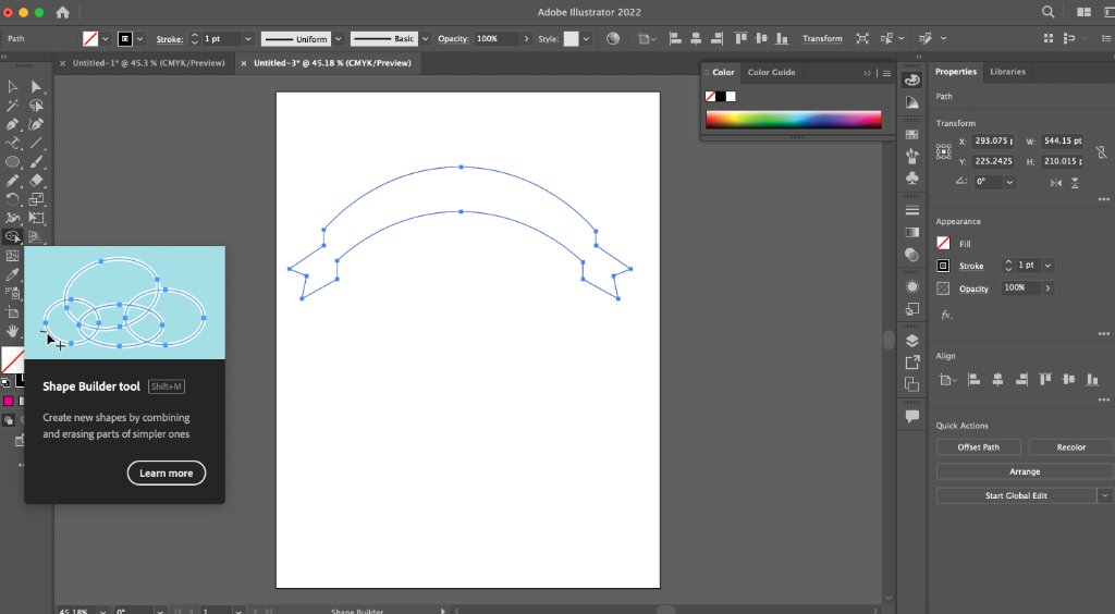
Select the ribbon and text outlines, then use the Pathfinder → Unite panel to combine
overlapping regions. Clean up any stray anchor points with the Shape Builder Tool
(Shift+M) so the artwork is one continuous cut path with no open gaps.
-
Export for Silhouette Studio:
 Save the file as SVG or copy the paths into Silhouette Studio. Confirm all strokes are expanded to
filled outlines — vinyl cutters need closed vector paths, not live text or hairline strokes.
Save the file as SVG or copy the paths into Silhouette Studio. Confirm all strokes are expanded to
filled outlines — vinyl cutters need closed vector paths, not live text or hairline strokes.
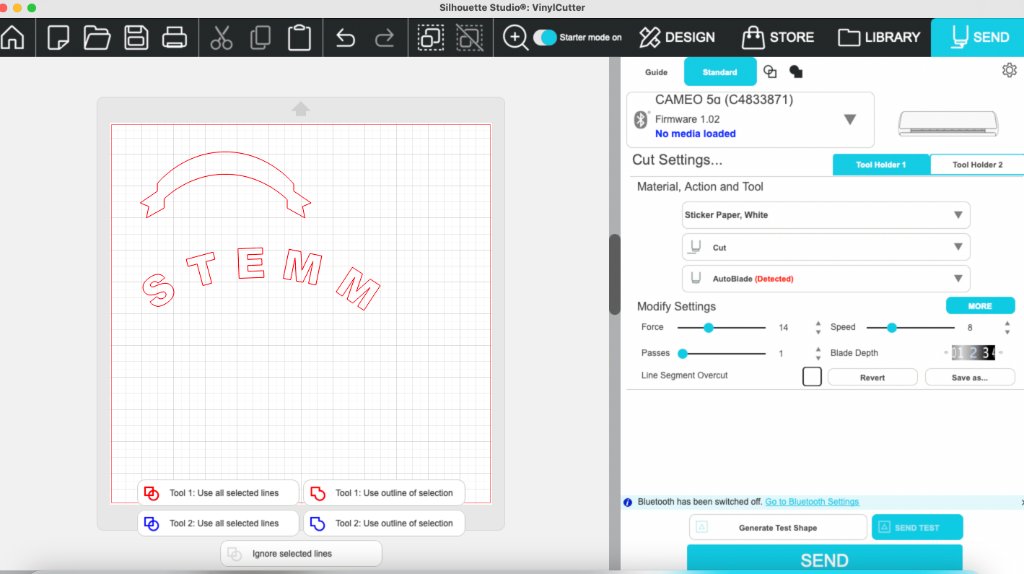
Silhouette Studio — print and cut
- Open the cleaned artwork in Silhouette Studio, switch to the Send tab, and load white sticker paper on the CAMEO 5 mat.
- Material preset: Sticker Paper, White; action: Cut; tool: AutoBlade.
-
Cut settings used: Force 14, Speed 8, Passes 1,
Blade depth 3. Ran a test shape first, then sent the full logo.
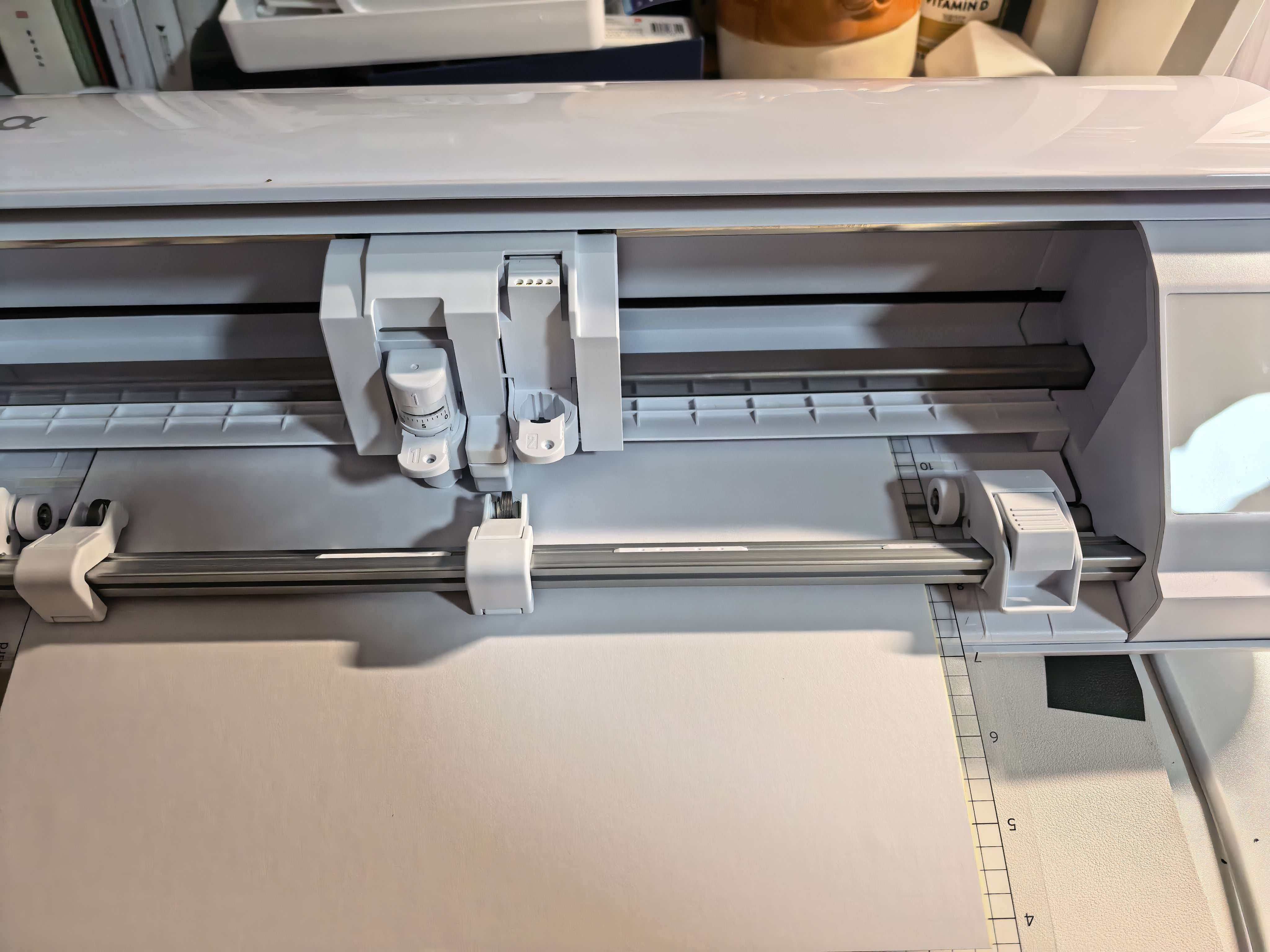
- After cutting, weed the excess vinyl and transfer the sticker with application tape onto the target surface.