

Software & Tools
Altium Designer
Schematic capture, PCB layout and routing, design rule checking.
26.3.0
Education

LPKF Circuit Pro
Gerber import, layer mapping, process planning, and toolpath generation for PCB milling.
2.5 PM
Lab machine software license
Arduino IDE
Sketch editing, board package management, uploading, and serial monitoring.
Version 2.3.7
Open Source (GNU AGPLv3)


PCB Design
As described above, these are the requirements for my new PCB. To reliably transmit a current of 12 Amperes, the traces were set to 5mm. Since the microcontroller itself does not require much current, its traces could be designed at only 1mm, which is more than sufficient.
For the PCB stack, I only used a single layer, as simple boards like this do not require top and bottom layers. For export from Altium, it was also important to include the board outline. Sometimes, the outline is not properly exported as a Gerber unless it is placed on a separate layer. I therefore added another mechanical layer and drew the outline there again.

When routing the traces, make sure that the traces do not form 90-degree angles, as this can cause critical errors during milling. Therefore, angles of 30 to 45 degrees are always recommended.
Now everything is ready for export. Go to PCB > File > Fabrication Outputs > Gerber Files. A pop-up appears. Only the necessary layers need to be selected. For example, I do not need silkscreens for simple milling with the LPKF. Silkscreens usually contain details like designators on the PCB - indicating which parts go where and therefore an idea of which exact components are used. This is helpful for large product chains and debugging, but for simple prototyping purposes not necessary. The exported file(s) can now be placed on a USB drive. To ensure everything was exported correctly, Altium has an internal CAM viewer, but there are also external options such as Altium Viewer and many more.
PCB Production
PCB Milling
Take the exported files and put them into your PCB machine. Refer to that documentation for a more detailed view of the PCB milling process. For this PCB, there are no especially important things to check, so milling this one is quite straightforward.
PCB Soldering
After the milling is done, you may now sand your board down and clean it with isopropanol. Then you can start attaching your components to the board. As usual, do not forget to check that the connections work properly with a multimeter. When everything looks fine, we can go ahead and connect the wires to the terminal.

Since the LEDs need higher power, we need to refer to an external power supply. As usual, when working with higher voltages, be careful, read any safety material, and work without power. Double-check that the wiring is correct and turn everything on only when there is proper space around the cabling.
PCB Programming
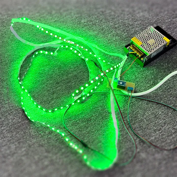
LED Strip Test
For testing, I created a simple code: each LED lights red sequentially. This allows me to check:
a) the number of LEDs, and
b) that each LED can be addressed and works correctly.
#include <Adafruit_NeoPixel.h>

#define LED_PIN     10
#define NUM_LEDS    200      // guessed amount LEDs | In the end 205

Adafruit_NeoPixel strip(NUM_LEDS, LED_PIN, NEO_GRB + NEO_KHZ800);

void setup() {
  strip.begin();
  strip.show();
}

void loop() {
  for (int i = 0; i < NUM_LEDS; i++) {
    strip.setPixelColor(i, strip.Color(255, 0, 0));
    strip.show();
    delay(200);
  }

  for (int i = 0; i < NUM_LEDS; i++) {
    strip.setPixelColor(i, strip.Color(0, 0, 0));
  }
  strip.show();
  delay(500);
}
ZigBee Integration
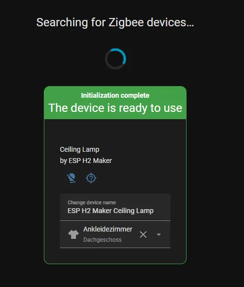
Once this worked, I uploaded the final ZigBee router code. It sets up a ZigBee signal, identifies as an RGB lamp, and allows third-party software - in my case Home Assistant - to control it.
The ZigBee setup is very similar to my Embedded Programming Week.
#include <Arduino.h>
#ifndef ZIGBEE_MODE_ZCZR
#error "Zigbee router mode must be selected in Tools -> Zigbee Mode"
#endif

#include "Zigbee.h"
#include <FastLED.h>

// ---------------- LED Setup ----------------
#define LED_PIN     10
#define NUM_LEDS    205
#define COLOR_ORDER GRB
#define LED_TYPE    WS2812
CRGB leds[NUM_LEDS];

// ---------------- Zigbee Endpoint ----------------
#define ZIGBEE_LIGHT_ENDPOINT 10
ZigbeeColorDimmableLight zbLight = ZigbeeColorDimmableLight(ZIGBEE_LIGHT_ENDPOINT);

// Callback to apply RGB + brightness
void onColorChange(bool state, uint8_t red, uint8_t green, uint8_t blue, uint8_t level) {
  if (!state) {
    FastLED.clear();
    FastLED.show();
    return;
  }
  float brightness = (float)level / 255.0;
  for (int i = 0; i < NUM_LEDS; i++) {
    leds[i].r = red * brightness;
    leds[i].g = green * brightness;
    leds[i].b = blue * brightness;
  }
  FastLED.show();
}

void setup() {
  Serial.begin(115200);

  // FastLED init
  FastLED.addLeds<LED_TYPE, LED_PIN, COLOR_ORDER>(leds, NUM_LEDS);
  FastLED.clear(); FastLED.show();

  // Set color capabilities (RGB/XY mode)
  zbLight.setLightColorCapabilities(ZIGBEE_COLOR_CAPABILITY_X_Y);

  // Bind callback
  zbLight.onLightChangeRgb(onColorChange);

  // Device info (optional)
  zbLight.setManufacturerAndModel("ESP H2 Maker", "Ceiling Lamp");

  // Register endpoint
  Zigbee.addEndpoint(&zbLight);

  // Start Zigbee as Router (extends mesh)
  if (!Zigbee.begin(ZIGBEE_ROUTER, false)) {
    Serial.println("Zigbee failed to start!");
    while (true) delay(1000);
  }
  Serial.println("Zigbee Router started");
}

void loop() {
  // No Zigbee.update() needed - handled internally
  delay(10); // Optional idle delay
}