

Software & Tools
Arduino IDE
Sketch editing, board package management, uploading, and serial monitoring.
Version 2.3.7
Open Source (GNU AGPLv3)


MicroPython
Lightweight Python runtime for microcontrollers, including REPL debugging and hardware scripting.
Version v1.27.0 (ESP32_GENERIC_S3)
MIT License (MicroPython)

Python
General-purpose programming language for scripting, automation, backend services, and data processing.
Version 3.8 (Conda environment)
PSF License
Houdini
Procedural Modeling, Simulation, Rendering
Build 21.0.440
Free Non-Commercial License (Apprentice)
Miniconda
Lightweight Python distribution used to create isolated, reproducible development environments.
Conda 24.11.3
Free Installer (Subject to Anaconda TOS/EULA)
PuTTY
Terminal emulator for SSH, Telnet, and serial communication with local or remote systems.
Version 0.83
MIT License
Home Assistant
Open-source home automation platform for device integration, dashboards, and rule-based automations.
Core 2026.2.2
Open Source (Apache 2.0)

Setup MicroPython
In this week’s assignment, I worked on setting up an ESP32-S3 with MicroPython to prepare for embedded programming. Below is the step-by-step setup workflow I used.
1. Installing Miniconda

Miniconda is optional for this workflow. If you prefer using your system Python directly, continue here. The main advantage of Conda is isolated environments with controlled Python and package versions, while working without Conda means installing tools globally, which can lead to dependency conflicts.
Installation is simple: download the installer for your operating system, run it, and follow the default setup steps.
After installation, create and activate a dedicated environment:
conda create --name esp32 python=3.8
conda activate esp32
This keeps all ESP32-related Python dependencies isolated from the main system environment.
2. Installing Required Packages
Inside the active environment, install esptool. If you are using Conda, you can install it directly from conda-forge:
conda install -c conda-forge esptool
This keeps package management fully inside the Conda environment and is useful when you want a Conda-only workflow.
If you prefer pip, use this command:
pip install esptool
This is the quickest option if you already use standard Python tooling in the same environment.
esptool is used to communicate with the ESP32 bootloader and flash firmware from the command line.
3. Downloading MicroPython Firmware
Download the firmware for ESP32_GENERIC_S3 from the official MicroPython page.
Make sure the firmware target matches the exact board family. For this workflow, I used ESP32_GENERIC_S3.
4. Erasing Flash Memory
Before flashing, erase the existing flash contents:
esptool --chip esp32s3 --port COM4 erase_flash
# deletes complete flash memory of the target board
Windows uses COM ports (for example COM4/COM5), while macOS and Linux typically use device paths like /dev/tty.* or /dev/ttyUSB0.

This command deletes all content in the flash memory. Verify the correct port in Device Manager before running it.
5. Flashing MicroPython Firmware
Navigate to the folder containing the downloaded firmware file and flash it:
esptool --port COM4 --baud 460800 write_flash 0 ESP32_GENERIC_S3-20251209-v1.27.0.bin
# writes MicroPython firmware to flash address 0x0
6. Verifying MicroPython Installation
To verify the installation, open a serial terminal like PuTTY:
Connection settings:
- Connection Type: Serial
- Port: COM5 (or the currently assigned ESP32 port)
- Baud rate: 115200
If setup is successful, a Python prompt appears and you can run Python code directly on the ESP immediately:
>>> print("Hello FabAcademy!")
Hello FabAcademy!
REPL means Read-Eval-Print Loop: an interactive shell where commands are executed directly on the microcontroller. Variables and imports stay in memory during the active session. If you want a clean state, press Ctrl+D for a soft reset, which restarts the MicroPython runtime and returns to a fresh REPL prompt.
Datasheets, Microcontrollers & Dev Boards
A microcontroller datasheet is the technical reference for the chip. It defines what the device can do, which electrical limits must be respected, how pins and peripherals are structured, and under which conditions the system operates reliably. It is less about application-level software design and more about making hardware and firmware work together correctly.
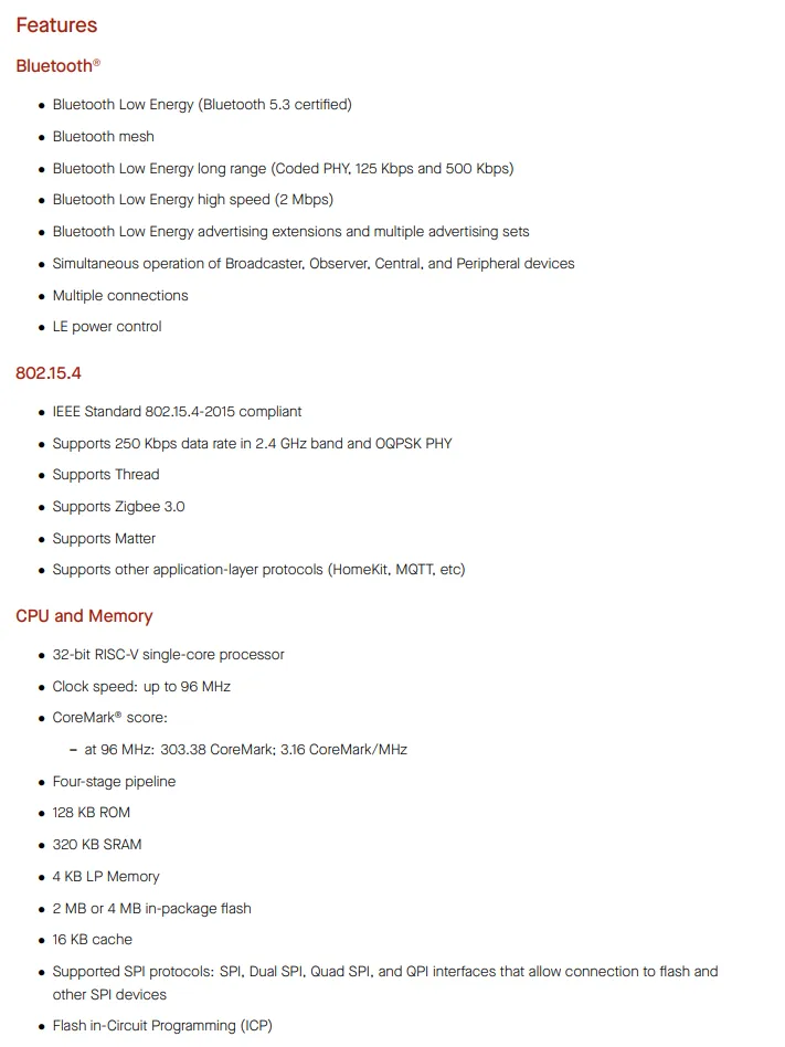
Key Features: Processor and Memory
The feature overview usually describes processing architecture, memory layout, clock behavior, and communication capabilities. This is where you estimate whether a controller matches your target workload, latency requirements, and connectivity needs before writing firmware.
In practical terms, ESP32-S3 is often selected when Wi-Fi and higher compute capacity are needed, while ESP32-H2 is often selected for lower-power wireless endpoints based on BLE or 802.15.4 protocols.
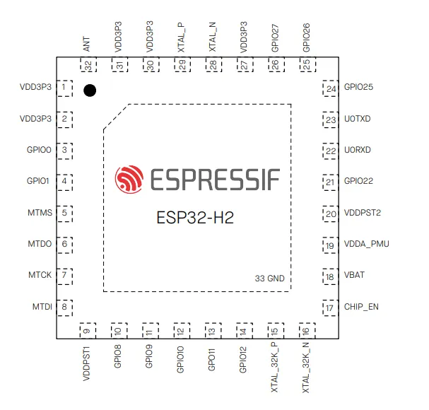
Pinout and Pin Functions
The pinout section maps physical pins to available functions and alternate modes. In practice, this is where you decide which signals are valid for UART, SPI, I2C, PWM, ADC, interrupts, and other hardware paths.
Applied to this comparison, ESP32-S3 generally offers more routing flexibility. On the microcontroller level, ESP32-S3 provides up to 45 GPIOs, while ESP32-H2 provides 19 GPIOs. The dev board comparison below refers to exposed dev board pins, which are lower and depend on dev board routing.
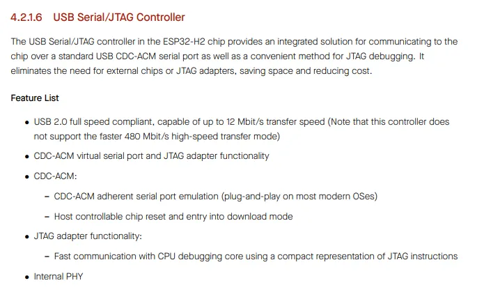
Peripherals and Interfaces
Peripherals are the built-in hardware modules that let the chip interact with the outside world, such as serial interfaces, timers, capture/compare units, and sensor-oriented inputs. Their datasheet chapters describe capabilities, limits, and timing behavior.
That is why ESP32-S3 is commonly used when USB or broader interface bandwidth is required, while ESP32-H2 is commonly used for compact control and low-power wireless sensing tasks.
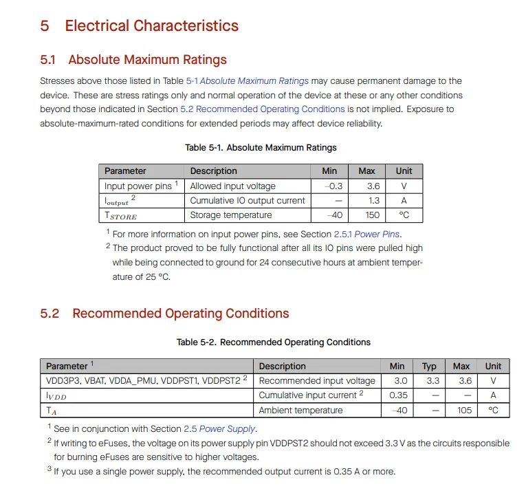
Power and Electrical Information
The electrical section defines supply voltage, current draw, thermal limits, and behavior across active and low-power states. These values are critical for power budgeting, regulator sizing, battery runtime estimates, and long-term stability.
Following this logic, ESP32-S3 is often used in performance-oriented systems, while ESP32-H2 is often preferred when low-power sleep behavior is a primary design requirement.
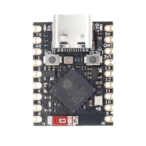
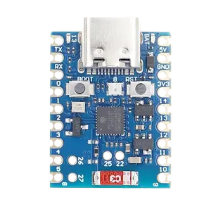
These values describe the microcontroller itself. In practice, many projects use dev boards such as ESP32-S3 Super Mini or ESP32-H2 Super Mini, where the chip is already integrated with additional board-level circuitry on power and signal paths. For this reason, you must also check the dev board documentation: it defines the final pin mapping, usable interfaces per exposed pin, real board-level power behavior, and extra hardware features such as on-board LEDs.

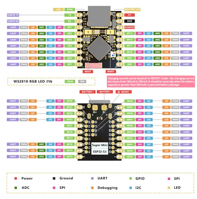
Dev Board References and Pinout
For development-board-specific details, the vendor shop page is usually the best starting point because it often links to the dev board datasheet and pinout diagram. For ESP dev boards, I recommend espboards.dev.
A pinout diagram shows exactly which functions are available on each exposed pin and what can be connected in practice. It also often marks onboard features such as status LEDs, which are useful for fast prototyping and debugging.
You should also verify which pins are reserved for boot, flashing, or other dedicated functions. Depending on the board variant, usable pins and pin numbering can differ, so always confirm the exact board mapping before wiring and assigning firmware pins.
Comparison: ESP32-S3 vs ESP32-H2
| USB Type: USB Type-C | USB Type: USB Type-C |
| WiFi: 802.11 b/g/n (2.4 GHz) | WiFi: - |
| Bluetooth: 5.0 | Bluetooth: 5.0 |
| BLE: 5.0 | BLE: 5.0 |
| Model: esp32s3 | Model: esp32h2 |
| Clock Speed: 240 MHz | Clock Speed: 96 MHz |
| Flash Size: 4 MB | Flash Size: 4 MB |
| Architecture: xtensa | Architecture: riscv32 |
| Exposed Digital IO (Dev Board): 11 | Exposed Digital IO (Dev Board): 11 |
| Exposed Analog Input (Dev Board): 6 | Exposed Analog Input (Dev Board): 6 |
| Exposed PWM (Dev Board): 11 | Exposed PWM (Dev Board): 11 |
| Exposed Interrupts (Dev Board): 22 | Exposed Interrupts (Dev Board): 22 |
|
Highlights: Ultra-small size: 22.52 x 18 mm. Ultra-low power: deep sleep around 43 uA. Onboard WS2812 RGB LED for programmable status indication. Dual-core Xtensa LX7 CPU up to 240 MHz. 512 KB SRAM, 384 KB ROM, 4 MB Flash. Security features: AES-128/256, RSA, HMAC, digital signatures, secure startup. |
Highlights: RISC-V 32-bit single-core CPU up to 96 MHz. 128 KB ROM, 320 KB SRAM, 4 KB low-power SRAM. 4 MB in-package flash memory. Supports IEEE 802.15.4 (Thread and Zigbee). Bluetooth 5 Low Energy support. Operates in the 2.4 GHz band with 250 Kbps data rate. USB Type-C interface for programming. Low-power operation for battery-powered devices. |


Control MicroPython via Houdini Inputs
I was wondering whether it would be possible to control an ESP from Houdini, or vice versa, so I could use real-world data to control the Houdini interface. I experimented a little and can confirm that it works. So here is what I did: to control the ESP directly from Houdini, I first had to connect two environments: Houdini’s internal Python runtime and the serial interface of the microcontroller. Houdini ships with its own Python installation and its own hou package, which allows direct access to node data, attributes, and procedural logic inside the scene.
I started this as an exploration project to test what is possible in a practical setup. I also prototyped a small package-management helper for Houdini so dependencies are loaded only when needed. It works for this project, but it is not production-ready yet, so the reliable approach is to install the required package directly into Houdini’s local Python interpreter.
Houdini Python Setup
Because the ESP board was already flashed with MicroPython, I could start immediately after installing serial support in Houdini’s Python environment:
# Navigate to Houdini's embedded Python
cd "C:\Program Files\Side Effects Software\Houdini 21.0.596\python311"

# Install serial package into this Python runtime
.\python.exe -m pip install pyserial

# Test in Houdini: Windows > Houdini Python Shell
import serial
Initialize a Global ESP Session in Houdini
The first Python node opens the serial connection, resets REPL state, initializes NeoPixel control, and stores the connection globally in hou.session so other nodes can reuse it.
import serial
import time
import hou


# Close old connection if available
if hasattr(hou.session, 'esp32') and hou.session.esp32 is not None:
    try:
        hou.session.esp32.close()
    except:
        pass

# Open new connection
esp = serial.Serial('COM5', 115200, timeout=0)
time.sleep(2)

# Enter raw REPL
# \x03 = Ctrl+C (interrupt running code), sent twice for a clean stop; \x01 = Ctrl+A (switch to raw REPL)
esp.write(b'\x03\x03\x01')
time.sleep(0.2)
esp.read(esp.in_waiting or 1)

# Initialize NeoPixel object on the board
# \n sends newline, \x04 sends Ctrl+D to execute the buffered command in raw REPL
esp.write(b'from machine import Pin;import neopixel;np=neopixel.NeoPixel(Pin(48),1)\n\x04')
time.sleep(0.2)
esp.read(esp.in_waiting or 1)

# Store globally for reuse in other nodes
hou.session.esp32 = esp
hou.session.esp32_ready = True

print("ESP32 initialized and stored in session")
print("You can now use it in other nodes.")
Read Simulation Attributes and Drive the ESP
A falling sphere creates stretch stress on the cloth. This attribute is generated by the simulation in Houdini. I read this behavior from the constraint attributes (like strings that hold the cloth together). The values are then normalized, an average is calculated, and the result is mapped to RGB color and brightness. The result is then streamed to the ESP in real time using the code below.
import hou
import serial
import time

def ensure_esp32_healthy():

    if hasattr(hou.session, 'esp32') and hou.session.esp32:
        esp = hou.session.esp32
        try:
            if esp.is_open:
                if esp.in_waiting > 500:
                    esp.read(esp.in_waiting)
                return esp
        except:
            pass

# Reconnect from scratch
esp = serial.Serial('COM5', 115200, timeout=0.5)
time.sleep(2)
# \x03 = Ctrl+C (interrupt), \x01 = Ctrl+A (enter raw REPL)
esp.write(b'\x03\x03\x01')
time.sleep(0.2)
esp.read(esp.in_waiting or 1)
# \x04 = Ctrl+D (execute current raw REPL command buffer)
esp.write(b'from machine import Pin;import neopixel;np=neopixel.NeoPixel(Pin(48),1)\n\x04')
time.sleep(0.2)
esp.read(esp.in_waiting or 1)

    hou.session.esp32 = esp
    print("ESP32 reconnected")
    return esp

# Main
esp = ensure_esp32_healthy()
node = hou.pwd()
geo = node.geometry()

# Clean serial buffer
if esp.in_waiting:
    esp.read(esp.in_waiting)

# Read simulation attributes
color = geo.attribValue('avgCd') if geo.findGlobalAttrib('avgCd') else (1, 0, 0)
brightness = geo.attribValue('stress') if geo.findGlobalAttrib('stress') else 1.0

r = max(0, min(255, int(color[0] * 255 * brightness)))
g = max(0, min(255, int(color[1] * 255 * brightness)))
b = max(0, min(255, int(color[2] * 255 * brightness)))

# Send with error handling
try:
    cmd = f'np[0]=({r},{g},{b})\nnp.write()\n'
    esp.write(b'\x01' + cmd.encode() + b'\x04')
    time.sleep(0.01)
    if esp.in_waiting:
        esp.read(esp.in_waiting)
except Exception as e:
    print(f"ESP32 error: {e}")
    hou.session.esp32 = None  # Force reconnect on next frame
Houdini to MicroPython Results
The final setup confirms stable communication and repeatable value updates frame by frame, creating a practical base for extending the workflow with additional attributes, sensors, and bidirectional control in the future. Stay tuned.
Control Home Assistant with Arduino via Zigbee
In addition to MicroPython, I also wanted to use Arduino to control a smart, dimmable light in my office. For this, I used a rotation sensor and an ESP32-H2. While I had an idea of how the sensor would work, I had never used it before, so I started by writing a simple test program.
// Analog Pin
#define POTI_PIN 4

// Config
#define READ_INTERVAL 50  // ms between measurements

void setup() {
  Serial.begin(115200);
  delay(1000);

  Serial.println("\nESP32-H2 Rotation Sensor Test");
  Serial.println("GPIO 4");

  // ADC config
  analogReadResolution(12);  // 12-bit ADC (0-4095)
  analogSetAttenuation(ADC_11db);
}

void loop() {
  static unsigned long lastRead = 0;

  if (millis() - lastRead >= READ_INTERVAL) {
    // Read ADC (0-4095 = 12-bit)
    int rawValue = analogRead(POTI_PIN);
    // Convert
    float percent = (rawValue / 4095.0) * 100.0;
    float degrees = (rawValue / 4095.0) * 300.0; // guessed 300 degree turn

    // Visualize
    Serial.print("Value: ");
    Serial.print(rawValue);
    Serial.print(" [");

    int bars = map(rawValue, 0, 4095, 0, 40);
    for (int i = 0; i < 40; i++) {
      if (i < bars) {
        Serial.print("█");
      } else {
        Serial.print("░");
      }
    }

    Serial.print("] ");
    Serial.print(percent, 1);
    Serial.print("% / ");
    Serial.print(degrees, 0);
    Serial.println("°");

    lastRead = millis();
  }

  delay(10);
}
Once I figured out the analog values the sensor outputs, I used mapping to adjust those values for my final program, which will eventually communicate with Home Assistant, an open-source smart home platform.
The core logic remains the same, but I mapped the sensor’s analog values (0-3504) to a range of 0-100, allowing me to get a percentage value for controlling the light’s brightness. This percentage dictates the light brightness level.
Additionally, I quickly added Zigbee support to my code with the help of Claude, as I find implementing Zigbee a bit tedious. Using a Large Language Model (LLM) like Claude was very helpful for this part.
#include "Zigbee.h"

#define POTI_PIN 4
#define ZIGBEE_ENDPOINT 10

// Calibration
int minValue = 0;
int maxValue = 3504;

// Smoothing
#define SMOOTHING_SAMPLES 10
int readings[SMOOTHING_SAMPLES];
int readIndex = 0;
int total = 0;

ZigbeeAnalog zbPoti = ZigbeeAnalog(ZIGBEE_ENDPOINT);

void setup() {
  Serial.begin(115200);
  delay(1000);
  Serial.println("\n=== Zigbee Potentiometer Router ===");

  analogReadResolution(12);
  analogSetAttenuation(ADC_11db);

  // Initialize smoothing buffer
  for (int i = 0; i < SMOOTHING_SAMPLES; i++) {
    readings[i] = 0;
  }

  // Zigbee setup
  zbPoti.setManufacturerAndModel("ESP H2", "Rotation Sensor");
  zbPoti.addAnalogInput();
  zbPoti.setAnalogInputDescription("Rotation Sensor");
  zbPoti.setAnalogInputMinMax(0, 100);

  Zigbee.addEndpoint(&zbPoti);
  Zigbee.setRebootOpenNetwork(180);

  Serial.println("Starting Zigbee...");
  if (!Zigbee.begin(ZIGBEE_ROUTER, false)) {
    Serial.println("Zigbee failed!");
    ESP.restart();
  }

  Serial.println("Zigbee OK! Waiting for connection...");
}

void loop() {
  static unsigned long lastRead = 0;
  static int lastValue = -1;

  if (millis() - lastRead >= 100) {
    int rawValue = analogRead(POTI_PIN);
    total = total - readings[readIndex];
    readings[readIndex] = rawValue;
    total = total + readings[readIndex];
    readIndex = (readIndex + 1) % SMOOTHING_SAMPLES;
    int smoothed = total / SMOOTHING_SAMPLES;

    // Map to 0-100 range
    int mappedValue = map(smoothed, minValue, maxValue, 0, 100);
    mappedValue = constrain(mappedValue, 0, 100);

    // Update if change > 2%
    if (abs(mappedValue - lastValue) >= 2) {
      Serial.print("Potentiometer: ");
      Serial.print(mappedValue);
      Serial.println("%");

      if (Zigbee.connected()) {
        zbPoti.setAnalogInput((float)mappedValue);
        zbPoti.reportAnalogInput();
      }

      lastValue = mappedValue;
    }

    lastRead = millis();
  }

  delay(10);
}
With the code written, I uploaded it to the ESP32. It is essential to ensure that the correct board and Zigbee settings are selected in Arduino IDE:
- Tools > Partition Scheme > Zigbee ZCZR 4MB with Spiffs
- Tools > Zigbee Mode > Zigbee ZCZR (coordinator/router)
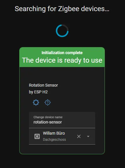
Once this setup is complete, the device should be accessible to Zigbee hubs.
For my smart home system, I am using a Raspberry Pi 5 with Home Assistant and a Sonoff Zigbee Dongle to provide Zigbee support. In Home Assistant, adding the device is straightforward: go to Zigbee > Add Device. Once added, a new sensor appears in the Home Assistant dashboard.
To control the light brightness with the rotation sensor, I used this Home Assistant automation:
Home Assistant Automation
# automation.yaml
- id: '1771000000000'
  alias: 'Control Light Brightness with Potentiometer'
  description: 'Controls the light brightness based on the potentiometer value.'
  triggers:
  - entity_id:
    - sensor.rotation-sensor
    trigger: state
  conditions: []
  actions:
  - target:
      entity_id: light.hue
    data:
      brightness: '{{ (states(''sensor.rotation-sensor'') | float) * 255 / 100 }}'
    action: light.turn_on
  mode: single
