Brand Story
The Brand
Smart-home clarity wrapped in a polished product story.
The current explanation page keeps its advertising energy here.
Brand Story
Smart-home clarity wrapped in a polished product story.
The current explanation page keeps its advertising energy here.
Making Of
Sketches, build decisions, prototypes, and the path behind the idea.
This view turns the project into a making-of documentation.
Today, most smart home systems are still guessing. Motion sensors trigger lights even when no one is really using a room. Heating schedules are static. The most essential information is missing:
Which room is currently in use – and by how many people?
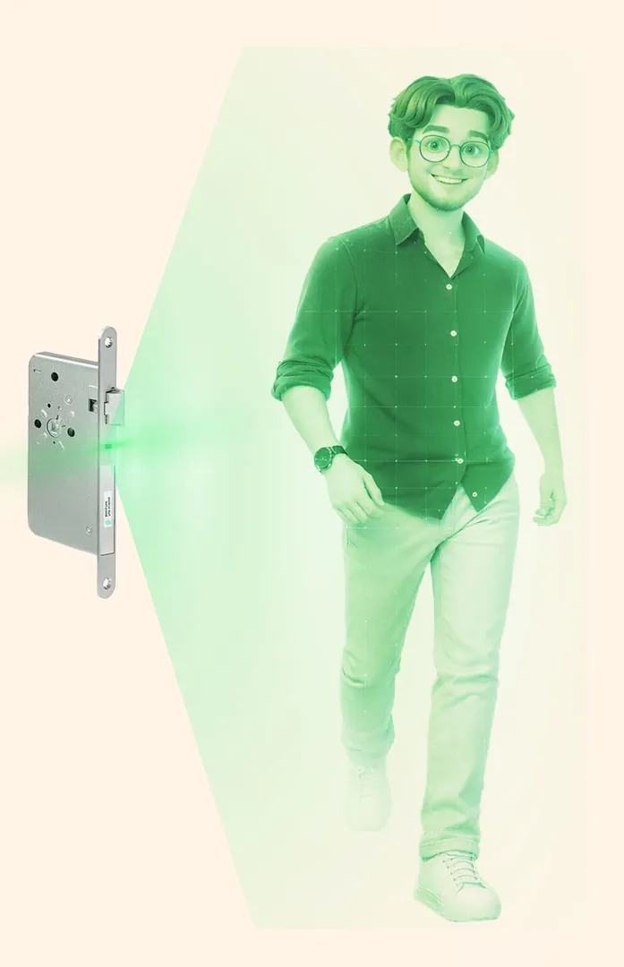
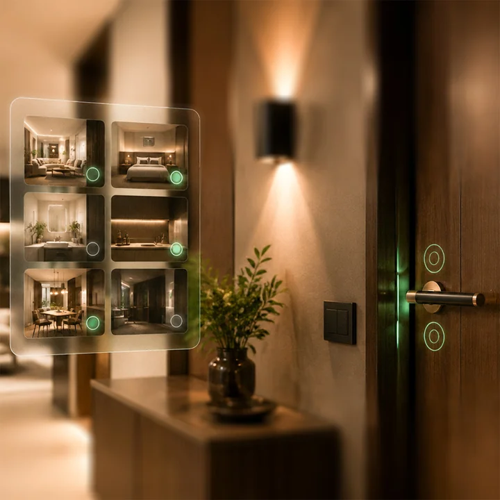
The Gate solves this problem by rethinking the door as the central interface of the smart home.
Instead of adding more sensors to ceilings or walls, The Gate replaces only one component: the standard mortise lock. Thanks to the DIN 18251 standard, which has been established for over 100 years, this solution can be installed in almost every German household – rental apartment, old building, or new construction – without drilling, rewiring, or visible hardware.

But knowing which room is occupied is only half the equation.
The other half is what happens next. Most smart home platforms still make presence-based automation feel like engineering work: navigating dashboards, writing automation scripts, and stitching together abstract helper entities just to turn off the lights when someone leaves a room.
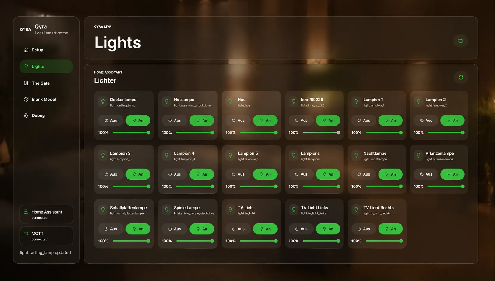
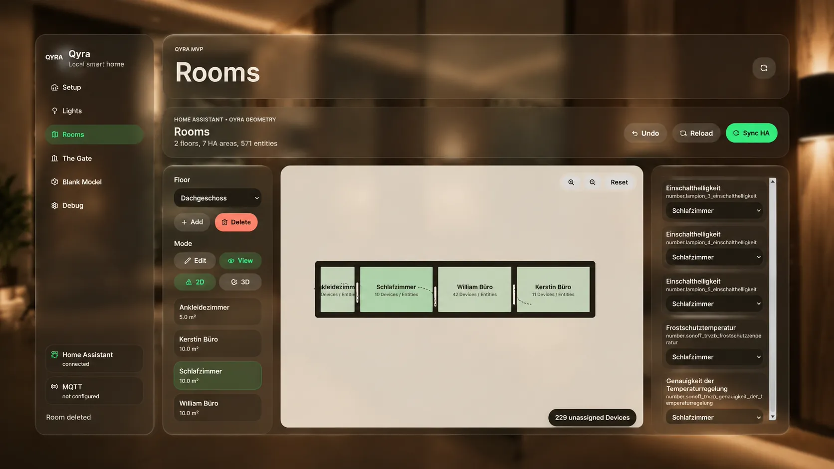
Qyra changes that. It is the interface The Gate was always meant to have: a smart home UI that thinks in rooms, not entities. You see your floor plan, you see who is where, and you set what should happen without a single line of YAML.
Lights, heating, scenes, and schedules all follow the same logic: the room knows who is in it, and Qyra knows what to do.
Designed to run alongside Home Assistant, Qyra keeps the flexibility and device compatibility of the world’s most powerful open home automation platform and replaces the only thing that was ever missing: a surface that anyone can actually use.
The Gate precisely differentiates between:
By detecting direction, movement, and interaction at the door itself, it knows when a room is actually being used. This enables truly smart behavior:
On top of that, The Gate introduces a new way of interacting with doors:
The door becomes an interface – not just a barrier.
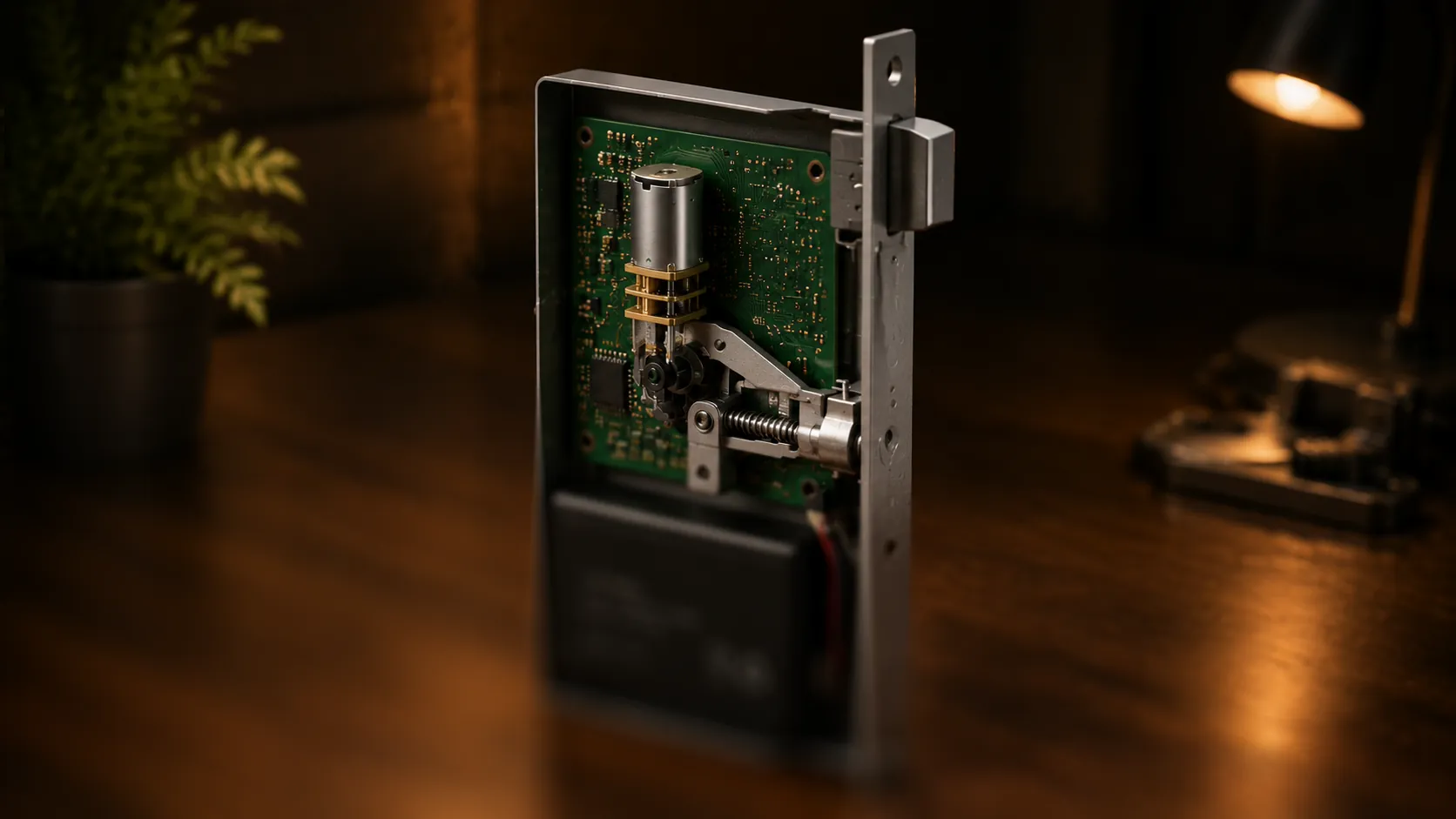
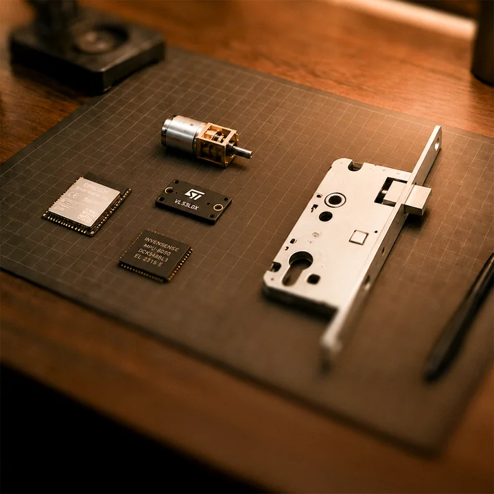
Inside the lock, The Gate combines multiple sensors:
All components are powered by a large internal battery, allowing a runtime of up to 9 months on a single charge.
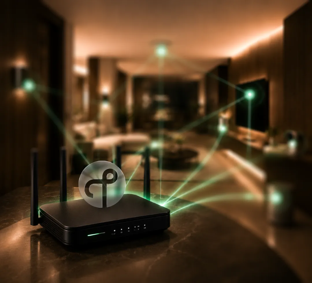
Communication is handled via Zigbee, using an ESP32-H2, making the system compatible with existing smart home ecosystems. The Gate does not add more devices to your home. It upgrades what is already there.
The door to truly smart homes is already built.![]() makes it intelligent.
makes it intelligent.

This project presents the first functional implementation of Qyra, a self-developed smart home platform built around a new way of thinking about presence in the home. The final consists of two closely connected components: Qyra | The Gate, a custom hardware device installed at a doorway, and the Qyra UI, the interface through which the system is configured and controlled.
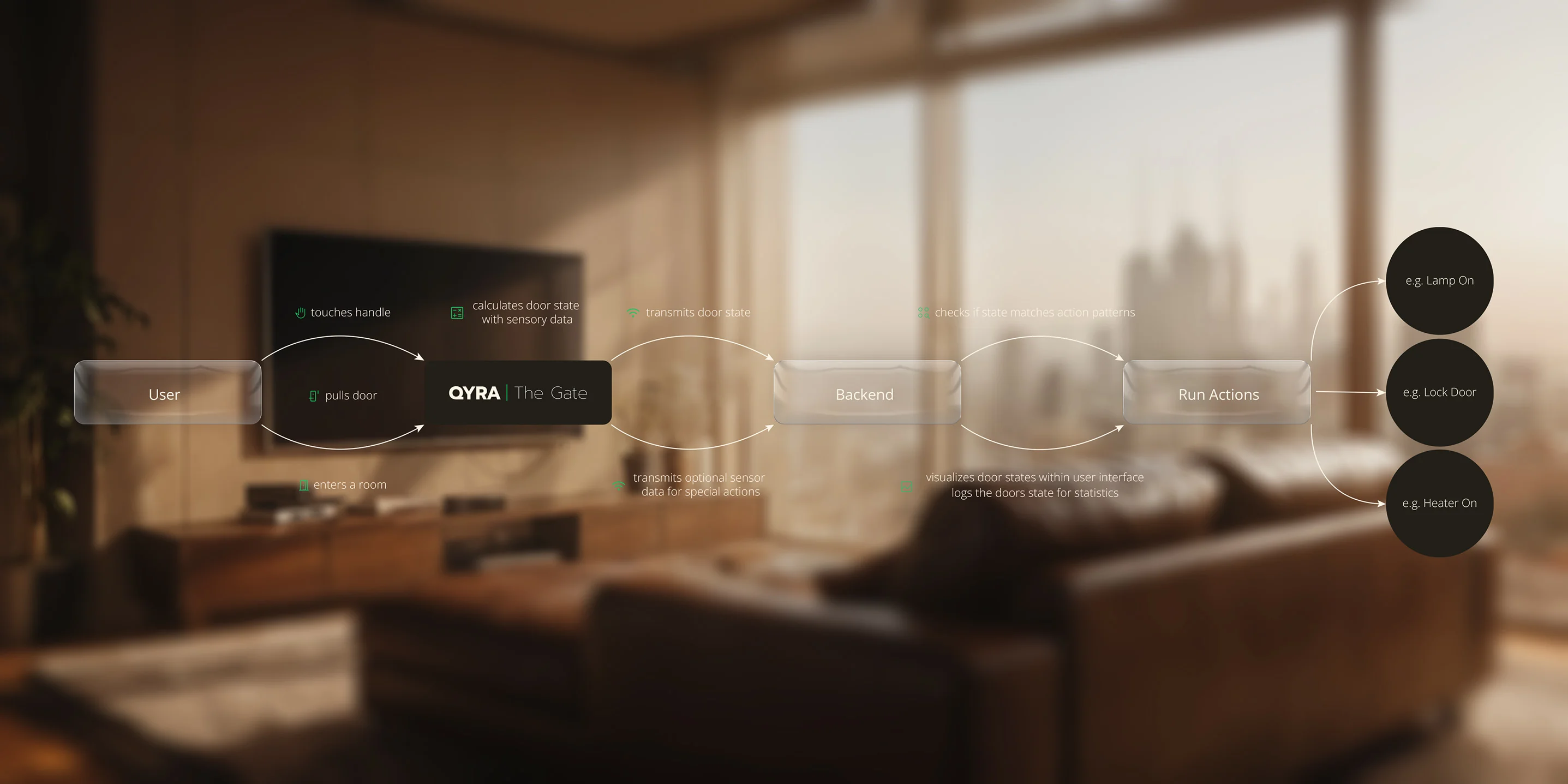
The Gate is built on an ESP32-H2 microcontroller paired with a VL53L5CX time-of-flight sensor. Using an 8x8 distance matrix captured at the doorway, it detects in real time whether a person is entering or leaving a room. All processing happens locally on the microcontroller itself: no cloud service, no external server, no round-trip to a backend. The ESP32-H2 derives the relevant states directly from the raw sensor data and publishes them as structured events into the local network, keeping latency minimal and the system fully independent of any internet connection.
These events are picked up by the Qyra Backend, a lightweight application running on a Raspberry Pi in the local home network. The backend connects to Home Assistant, the open-source device integration platform that manages all smart home hardware in the background, and uses the presence events from The Gate to trigger device control across the entire home. Lights, heating, switches, and any other Home Assistant-connected device can be configured to respond automatically when a room becomes occupied or vacant.
This configuration is handled entirely through the Qyra UI: a modern, browser-based interface that presents the home as a floor plan, maps The Gate devices to their respective doorways, and lets users define room-level device behaviour without writing automations or managing abstract helper entities.
Home Assistant and the Qyra Backend are designed to run on the same Raspberry Pi, sharing a single piece of hardware with minimal overhead. They can equally be separated onto individual devices if a particular setup requires it, making the architecture flexible from the start.
The scope of this final project is deliberately focused: the goal is to demonstrate the core loop in a working state. A person walks through a door, The Gate detects the direction of movement, the Qyra system identifies which room has been entered or vacated, and the connected devices respond accordingly. Everything is configured and monitored through the Qyra UI.
The project was organized through a task board and calendar view, making it easier to keep track of open decisions, planned milestones, and the time available for each part of the build.
The task overview keeps the build process structured, from open decisions to finished milestones.
The calendar maps project phases, test windows, and documentation steps across the available time.
This diagram shows how the system works, where data is transmitted, and how results are calculated from the first input to the final output.
Door Hardware, Electronics and Handle Integration
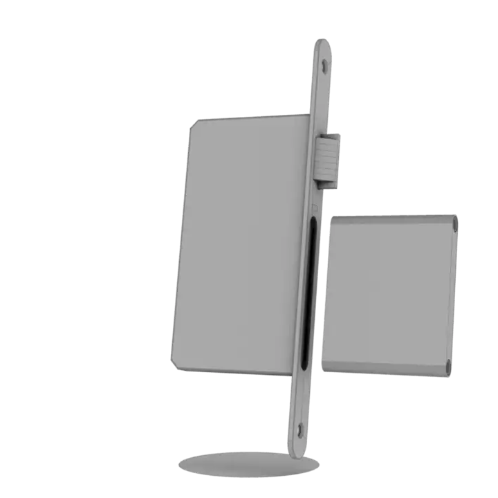
Physical integration is the main constraint of The Gate because the system has to fit into the geometry of a standard German interior door and follow the spatial logic defined by DIN 18251, while still disappearing into the existing lock and handle assembly.
The design therefore treats standards, packing, lock mechanics, capacitive sensing, haptic feedback, and power transfer as one compact mechanical-electrical stack. Every signal path and component position has to support the door hardware first, so the system can remain robust, cable-minimal, and installable in a real lock body.
The physical design is built around DIN 18251 and the geometry of a typical German interior door. This makes the standard itself one of the largest constraints: the lock, handle position, square spindle, latch movement, and surrounding installation space have to stay within the expected dimensions instead of being freely redesigned around the electronics.
Using a standard room door as the base keeps the prototype close to a real installation scenario. The goal is not to create a special demonstration door, but to make The Gate fit into the same mechanical conditions that already exist in everyday interior doors.
The internal packing is designed to avoid loose cables wherever possible. Most connections are routed as PCB traces and the board is populated with SMD components, so the electronics remain compact, fixed in place, and less vulnerable to movement inside the lock body.
The ToF sensor requires a 90 degree direction change to face the doorway correctly. The current plan is to solve this with 90 degree Dupont pins and headers, although this connection is still being evaluated. For possible I2C extensions, JST connectors are planned; because the battery takes up the available internal space, this may become the only cable connection and would be fixed to the lower part of the housing.
The square spindle is also planned without cables running through or around it. Keeping the spindle mechanically clean makes the lock safer to install and should make the assembly more resistant to drops and repeated impacts.
The door is locked with an N20 motor. Its gearbox makes it extremely difficult to push the handle down once the mechanism is engaged. The motor moves roughly 10 degrees to block the follower, making the door almost impossible to open.
The mechanism was designed with the user experience in mind: the geometry allows a complete lock action within approximately 80 ms.
To make the system controllable through the handle itself, the handle becomes part of the capacitive sensing path. One signal is routed through the handle and the GND connection to the capacitive sensor.
On the opposite side, the VCC connection carries the signal to a second sensor pin. A P-MOSFET switches this path between capacitive sensing and power delivery.
A vibration motor gives the user quiet, immediate feedback. It is powered through an N-MOSFET, with current flowing through the VCC layer and returning through GND.
During vibration, the P-MOSFET disconnects the line from the touch sensor to protect the IC. Touch data is unavailable for that short moment, but the system avoids additional data lines through the handle shaft.
The power system carries both GND and VCC while also serving as the electrode path for touch sensing. On the shown side, the electrode runs through GND; on the opposite side, it runs through VCC.
A slip-ring-like contact keeps GND and VCC connected even while the follower rotates. Spring-loaded contacts press against the handle shaft, which is inserted through the lock like a normal door handle shaft. The gearbox remains fixed inside the lock.
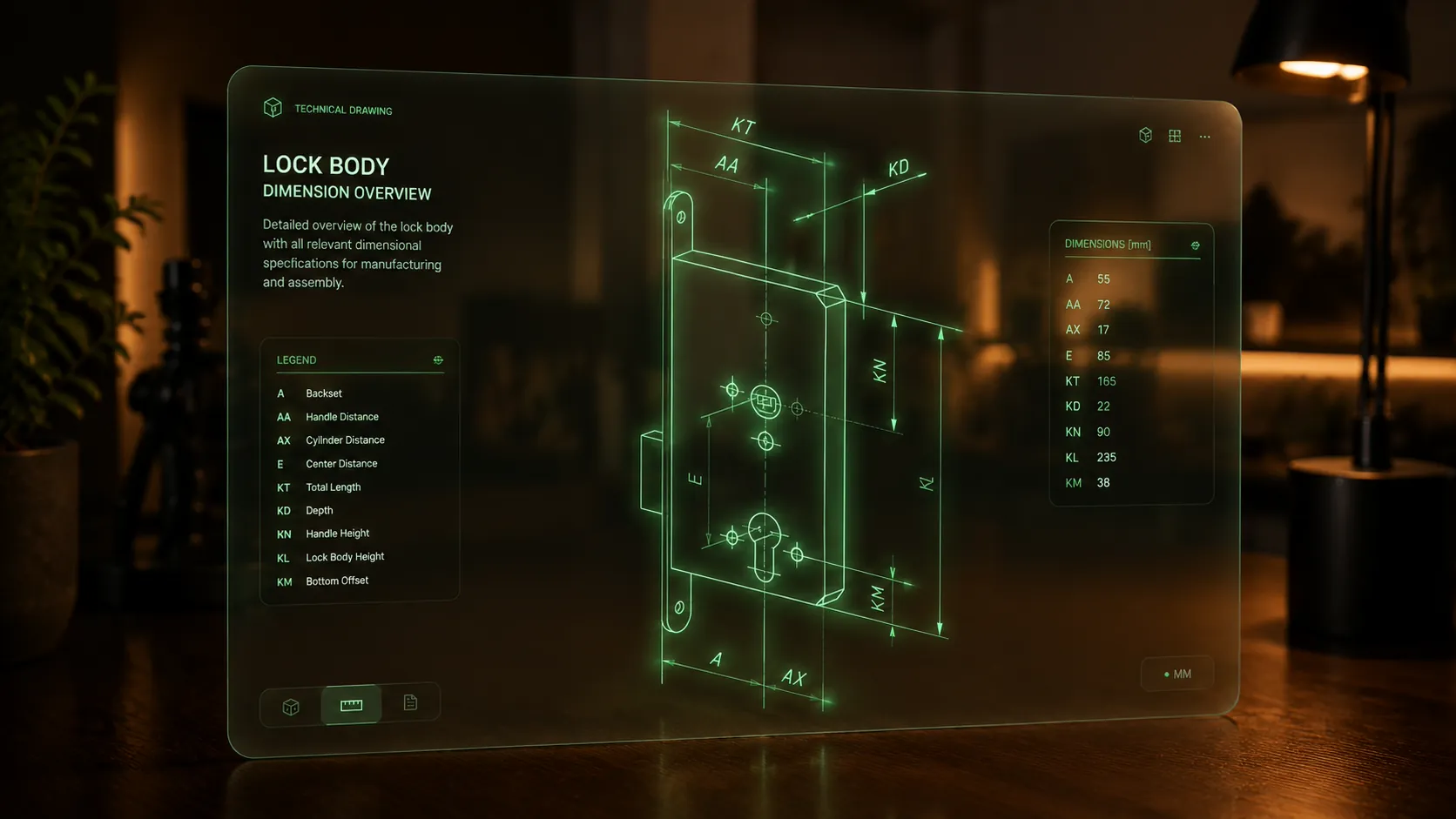 Image AI Generated with GPT 5.5
Local Events, Room Logic, Home Assistant Control
The software integration keeps The Gate local: the ESP32-H2 turns raw sensor input into doorway events, while Home Assistant remains the compatibility layer for Matter, Thread, Zigbee, Wi-Fi, and MQTT devices.
Qyra sits above that device layer and translates technical state changes into room-level behavior, so the interface can describe what should happen in a space instead of exposing users to entity names and automation plumbing.
 Image AI Generated with GPT 5.5
The ESP32-H2 on The Gate continuously reads all sensor values: the ToF matrix, gyroscope, and capacitive touch sensor. All processing happens directly on the chip.
The result is a structured event, for example { direction: "enter", room: "living_room" }. This event is transmitted over Thread, an IPv6-based mesh protocol that operates without Wi-Fi overhead.
A Thread Border Router, for example the Home Assistant SkyConnect ZBT-2 or Home Assistant Yellow, connects the Thread mesh to the regular IP home network.
It translates Thread packets into standard IPv6 traffic. From this point on, The Gate is addressable like any other network device.
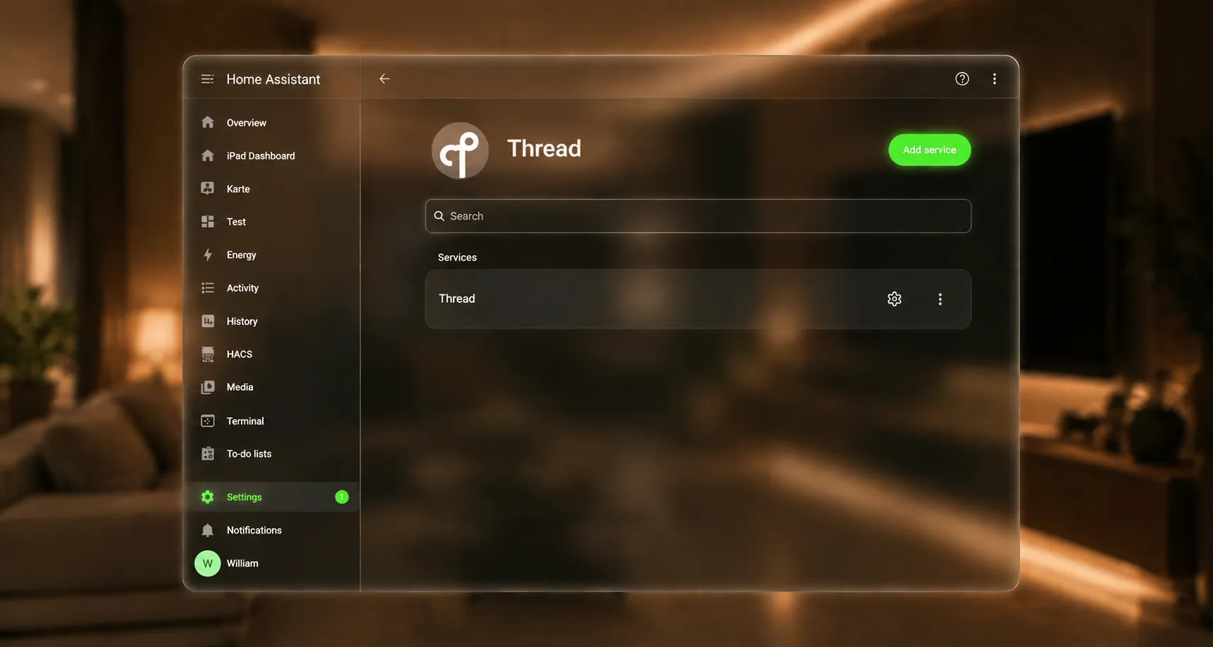
Home Assistant runs the OpenThread Border Router as an add-on and manages the Thread network directly. The Gate registers with Home Assistant via Matter over Thread through a simple QR code commissioning process.
After that, it appears in Home Assistant as a device with its own entities, such as binary_sensor.the_gate_presence or sensor.the_gate_direction.
The Qyra Backend maintains a persistent WebSocket connection to Home Assistant at /api/websocket and subscribes to all state_changed events.
As soon as Home Assistant registers a state change from The Gate, or from any other device, the backend receives it in real time.
The backend also sends control commands back to Home Assistant through the same WebSocket connection. These commands are triggered automatically by user-defined room reactions in the Qyra UI, or manually when a user controls a device in the interface.
In both cases, the backend calls the appropriate Home Assistant service, such as light.turn_on, climate.set_temperature, or switch.toggle. Home Assistant executes the command and controls the physical device.
The backend simultaneously maintains a WebSocket connection to the frontend via socket.io, forwarding processed events and current device states in real time.
The frontend never communicates directly with Home Assistant. It talks exclusively to the Qyra Backend.
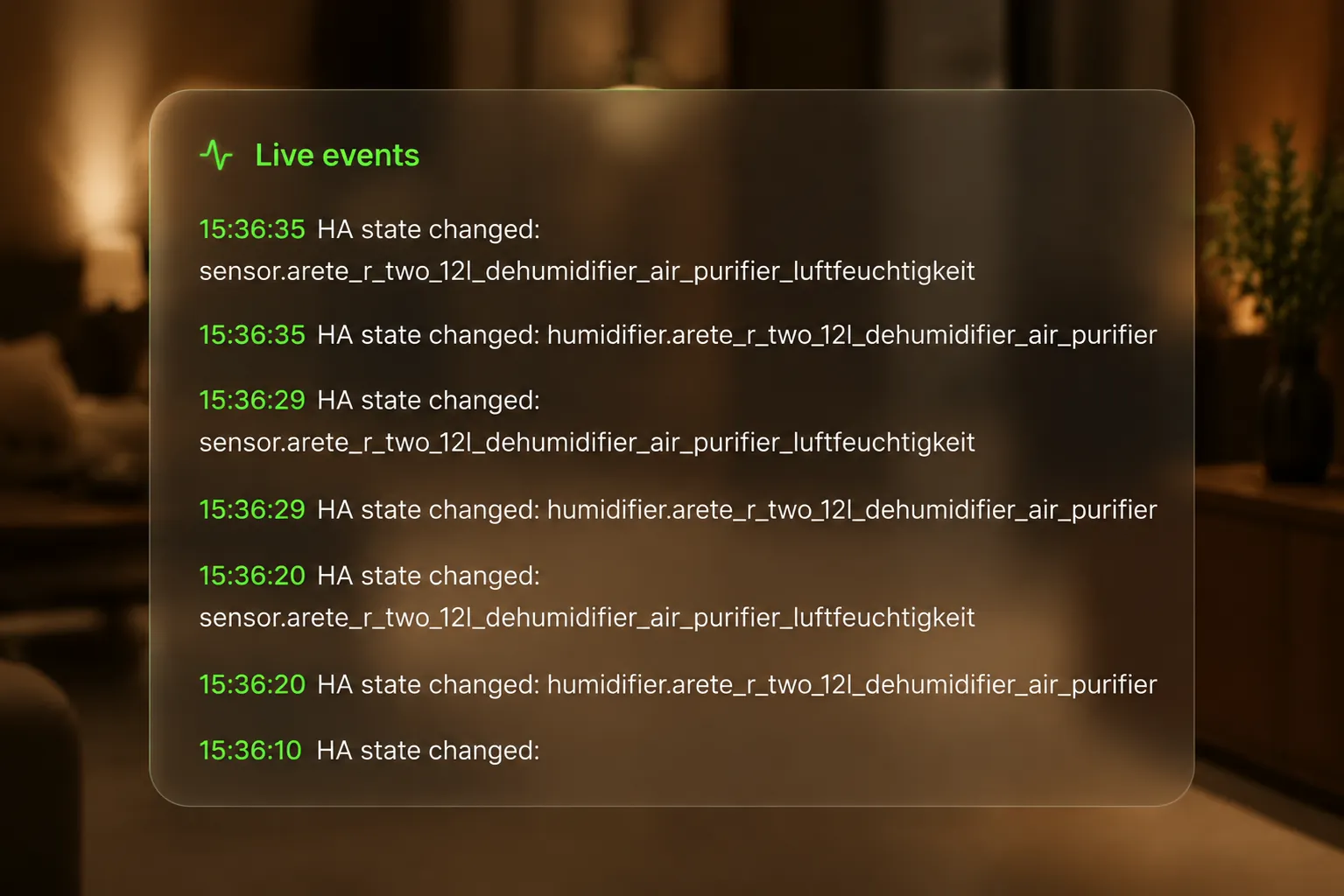
The React app in the browser receives events and updates the UI immediately: which room is occupied, which devices are active, and what The Gate is currently detecting.
Control commands from the UI, such as manually switching a light, travel back through the same path: Frontend to Backend to Home Assistant to Device.
Beyond The Gate and Thread devices, Home Assistant integrates the full range of hardware found in a typical smart home. Zigbee devices can run through ZHA or Zigbee2MQTT, Wi-Fi devices connect through their Home Assistant integrations, and MQTT devices publish to a broker that Home Assistant subscribes to.
From the Qyra Backend's perspective, the connection method does not matter. It sees one consistent API surface and one unified device model.
QYRA | The Gate will precisely track room occupancy as well as the number of people currently inside a room. The system is designed to detect presence changes reliably, report both occupancy state and people count, and make that information available to connected services and interfaces.
In addition, The Gate will not only act as a sensor system, but also as an interaction point for the smart home. Through Qyra's own UI platform, the system will be able to control smart home products that are connected through Home Assistant, turning the room itself into an input and automation interface. The goal is to create a product that combines presence detection, room intelligence, and intuitive control seamlessly.
The project is being developed largely from scratch. While there was an earlier prototype phase used to explore the idea and general direction, this version is the first professional implementation of the concept.
None of the old hardware, layouts, or collected data are being reused in the final development process. This means the current project is not just a revision of an older prototype, but a complete redesign with a much higher technical and mechanical standard.
Home Assistant will be used as the main basis for integrating smart home products into the system. It provides the interface through which external devices can be connected to the Qyra pipeline, making it possible to monitor states and control smart home objects through a unified platform. As an open-source ecosystem, it is especially suitable because it is flexible, widely used, and well supported by the community.
The project also uses the DIN 18251 standard as a structural reference for the lock format. This makes it possible to design the product around an established mechanical standard rather than inventing all dimensions from scratch, which improves compatibility and makes The Gate more realistic as a product concept.
The casing, the PCB, the logo, the packaging, and the handles of the door will be designed from scratch, replacing the complete mortise lock while reusing DIN-based dimensions where required. This means the project is not limited to electronics, but includes the full product design process from internal mechanics to the external appearance.
The design work therefore covers both engineering and branding. In addition to the technical functionality, QYRA | The Gate will receive a complete visual identity and a mechanically integrated housing concept tailored specifically to the selected components and intended use case.
For the casing, 1 mm aluminum sheets will be used as the top and bottom closing parts in order to improve scratch resistance and provide a more durable outer shell. The structural core of the assembly will be made from 3D-printed parts, primarily in ABS, because ABS offers better long-term durability and mechanical strength than PLA for this type of application. PETG is also being considered as a possible alternative, depending on the final mechanical requirements.
The handle will be made from wood (exact wood type pending). Inside, it will contain a 3D-printed core structure that holds a small PCB for the vibration motor and provides the connection to the touch-sensing electrodes. Aluminum sheets will be integrated seamlessly into the handle and used as electrodes for touch measurement.
The PCBs themselves will be made from FR4. These boards will be assembled with the components ordered for the project, including sensors, wireless modules, power-management ICs, connectors, protection parts, and standard passive components.
Most components will be ordered through DigiKey. The main PCB will be manufactured by JLCPCB, and the corresponding solder paste stencil will also be ordered to support efficient and repeatable assembly.
Any additional parts, tools, or small supporting materials that are not part of the main order will be taken from the lab. This approach keeps the sourcing process practical while still relying on professional suppliers for the critical custom parts.
The DigiKey order currently totals roughly €240. However, many parts were intentionally ordered more than once, or in larger quantities than strictly necessary, in order to reduce the risk of project delays caused by assembly mistakes, damaged parts, or design revisions.
Regarding the custom printed circuit boards, the main PCBs manufactured by JLCPCB cost €4.20 per piece including shipping, subject to a required minimum order quantity of five pieces. The corresponding solder paste stencil was ordered for an additional €8.00, which has no minimum order requirement.
Because of that, the current number should not be understood as the exact per-unit product cost. A more precise and meaningful total will be calculated once the development of The Gate is finished and all final manufacturing, sourcing, and assembly decisions have been completed.
Using the populated PCB BOM quantities, the Seeed module at €4.00, one battery at €15.00, one main PCB at €4.20, and approximately 200 g of filament estimated at €4.00, the current v1 build cost is roughly €52 per unit, excluding flux, solder paste, solder wire, and one-off tooling.
A mainboard PCB will be created that fills almost the entire mortise lock body. This board contains the main CPU and nearly all major sensors, making it the central control board of the whole system.
The ToF sensor board will be designed as a separate PCB because it must be rotated by 90 degrees to fit properly into the mechanical structure. There will also be a dedicated charger PCB that allows the battery to charge at 600 mA, and each vibration motor inside the handles will receive its own small PCB as well.
In addition, a sliding mechanism for the battery pack will be developed, along with a compact and visually integrated housing for all electronic and mechanical components. Each handle will also be built from scratch so that it fits the sensors, wiring, and internal parts precisely instead of adapting the electronics to an off-the-shelf handle.
The main PCB will be manufactured externally, while the smaller PCBs will be milled using an LPKF machine. Most electronic components will be placed with solder paste and reflow-soldered in an oven, while a smaller number of components will be soldered by hand where necessary.
The handles will be milled on a portal milling machine. The aluminum sheets will be cut with the xTool MetalFab, logos will be engraved with the xTool F1 Ultra, and the casing parts will be printed on Bambu X1 Carbon printers with AMS. Altogether, the manufacturing of QYRA | The Gate combines PCB manufacturing, CNC machining, laser processing, engraving, and additive manufacturing in one workflow.
Several important design and engineering questions still need to be resolved during development. These include the final PCB dimensions, possible design constraints caused by the DIN-based size requirements, the internal mechanism layout, the locking mechanism concept, and the sliding mechanism for the battery pack.
In addition, the project must evaluate whether the handles can trigger touch measurement reliably enough in real use, whether the ESP32-based system can remain in a sufficiently low-power state for several months of battery life, and which mechanical concepts are best suited for locking and battery access. Practical questions such as PCB and component delivery times also matter, because they affect how development time can be used efficiently while waiting for parts.
A. The first criterion is whether The Gate can actually detect people entering a room and report that state correctly. The occupancy result and people count must be reliable enough to make the system useful in practice.
B. The second criterion is whether The Gate can remain in a very low-power sleep state and wake up only when relevant events occur. This is essential for making the system practical as a battery-powered product.
C. The third criterion is whether the system creates a genuinely new way to interact with rooms, doors, and smart home functions. The project should not only work technically, but also provide a more natural and integrated user experience.
D. The fourth criterion is whether the UI behaves as intended and correctly controls smart home objects that are integrated through Home Assistant. The full chain from sensing to interface to smart home action must work as one consistent system.
May 11–15
The final development phase kicked off on May 11 with a thorough system integration session that stretched over three days. The primary focus was on understanding how all subsystems would work together — the slip ring mechanism was analyzed in detail, fundamental dimensional measurements were taken, and the CAD model was rebuilt from the ground up to accurately reflect the physical hardware constraints that had emerged up to that point. This foundational work was essential before any further design decisions could be made with confidence.
Following the integration analysis, attention shifted to electronics research from May 13 to 15. Components were identified, availability and lead times assessed, and a DigiKey order was placed to source everything needed for the upcoming build phases.
BOM & DigiKey Order
Core electronics
These are the more distinctive functional parts of the design, including the wireless module, sensors, control ICs, and motor-driving hardware.
| Name | ID | Qty | Price | Link | Description |
|---|---|---|---|---|---|
| ESP32-H2 wireless module | 1965-ESP32-H2-MINI-1-H2SCT-ND | 0 | €3.19 | DigiKey | Compact wireless module used as the main embedded communication/control element. |
| Seeed XIAO ESP32-C6 module | XIAO ESP32 C6 | 1 | €4.00 | - | Module used for the simplified in-house milled mainboard. |
| ToF optical sensor | 497-VL53L5CXV0GC/1CT-ND | 1 | €7.39 | DigiKey | Optical distance sensor for short-range presence or position measurement. |
| Capacitive touch sensor | 1790-IQS323001DNRCT-ND | 1 | €0.58 | DigiKey | Detects touch input on capacitive electrodes. |
| Accelerometer | 497-14851-1-ND | 1 | €1.35 | DigiKey | Motion sensor for detecting orientation, movement, or vibration. |
| Motor driver IC | 296-34806-1-ND | 0 | €0.96 | DigiKey | Drives a small DC motor or actuator from the control electronics. |
| Inverter logic IC | 296-11599-1-ND | 0 | €0.08 | DigiKey | Simple single-channel logic inverter for signal conditioning. |
| Analog switch IC | 296-18015-1-ND | 0 | €0.15 | DigiKey | Routes or switches low-level signals between different paths. |
Power and protection
These parts handle voltage conversion, battery charging, power-path control, and electrical protection for the system.
They are important for making the design efficient, battery-safe, and more robust against shorts, ESD, and wiring mistakes.
| Name | ID | Qty | Price | Link | Description |
|---|---|---|---|---|---|
| Buck regulator | 175-MAX38641AELT+TCT-ND | 0 | €2.26 | DigiKey | Efficient step-down regulator used to generate a lower supply voltage. |
| Buck regulator | 296-TPS628438YKARCT-ND | 0 | €1.35 | DigiKey | Compact step-down regulator for low-power voltage rails. |
| Li-ion charger IC | MCP73831-2DCI/MC-ND | 1 | €0.70 | DigiKey | Single-cell lithium charging controller. |
| Li-ion battery | Battery pack | 1 | €15.00 | - | Main rechargeable energy storage for the assembled unit. |
| Power-management IC | 296-LM66200DRLRCT-ND | 0 | €0.54 | DigiKey | Manages power routing or supply selection within the circuit. |
| Battery protection IC | 5399-DW01ACT-ND | 0 | €0.02 | DigiKey | Protects a single-cell lithium battery against unsafe operating conditions. |
| Dual MOSFET for battery protection | 5272-FS8205ACT-ND | 0 | €0.33 | DigiKey | Companion switching device typically used with battery protection circuitry. |
| Resettable fuse, 100 mA | 118-MF-ASML010/6-2CT-ND | 0 | €1.39 | DigiKey | Self-resetting fuse for low-current overcurrent protection. |
| Resettable fuse, 750 mA | 118-MF-ASML075/6-2CT-ND | 1 | €1.74 | DigiKey | Self-resetting fuse for higher-current protection. |
| TVS / ESD protection diode | DF6A6.8FUT1GOSCT-ND | 0 | €0.65 | DigiKey | Protects exposed lines against transient overvoltage and ESD events. |
| TVS / ESD protection diode | 296-39341-1-ND | 2 | €0.24 | DigiKey | Protects sensitive signal lines from electrostatic discharge. |
| TVS / ESD protection diode | 497-5235-1-ND | 0 | €0.33 | DigiKey | Protection device suited for external connector lines such as USB. |
| N-channel MOSFET | 785-1000-1-ND | 2 | €0.32 | DigiKey | General-purpose low-side electronic switch. |
| P-channel MOSFET | DMG3415UDICT-ND | 0 | €0.25 | DigiKey | General-purpose high-side switching element. |
| Power transistor | TIP31BGOS-ND | 0 | €1.07 | DigiKey | Through-hole NPN transistor for switching higher loads. |
| Power transistor | TIP3055GOS-ND | 0 | €2.80 | DigiKey | Higher-power NPN transistor for more demanding switched loads. |
| Schottky diode | 4878-BAT54CT-ND | 0 | €0.08 | DigiKey | Fast, low-drop diode for signal or power steering. |
| Schottky diode | 5399-B5819WCT-ND | 2 | €0.05 | DigiKey | Low-loss diode for power-path or reverse-polarity related tasks. |
Passive parts
These are the supporting passive components used for filtering, timing, current limiting, pull-ups, biasing, and regulator stability.
They are less unique than the ICs, so grouping them makes the list easier to review.
| Name | ID | Qty | Price | Link | Description |
|---|---|---|---|---|---|
| SMD resistor assortment | Multiple IDs including 311-100LRCT-ND, 311-1.00KLRCT-ND, 311-22.0LRCT-ND, 311-240KLRCT-ND, 311-2KLRCT-ND, 311-3.30KLRCT-ND, 311-470LRCT-ND, 311-4.7KLRCT-ND, 13-RC0402FR-071M1LCT-ND, 2019-RK73G2ATTD1003FCT-ND, 2019-RK73H1ETTP4702FCT-ND, 2019-RN73H1ETTP1673F25CT-ND, 2037-PFR05S-221-FNHCT-ND, P5.1KDCCT-ND, RMCF0402FT10K0CT-ND, RMCF0402FT249KCT-ND | 16 | €0.0077 to €0.108 | DigiKey search | Standard SMD resistors used for pull-ups, pull-downs, voltage dividers, current limiting, and signal conditioning. |
| Ceramic capacitor group | 399-C0402C105K9PACTUCT-ND, 490-3261-1-ND, 490-3886-1-ND | 11 | €0.0112 to €0.0400 | DigiKey | MLCC capacitors used for decoupling, local energy storage, and noise filtering. |
| Tantalum capacitor | 478-5231-1-ND | 0 | €1.25 | DigiKey | Higher-value capacitor for bulk supply buffering. |
| Inductor | 445-15732-1-ND | 0 | €0.22 | DigiKey | Small SMD inductor used in switching power stages. |
| Inductor | 732-3333-1-ND | 0 | €2.00 | DigiKey | Higher-current inductor for power conversion circuitry. |
| Red indicator LED | 516-3060-1-ND | 1 | €0.51 | DigiKey | Small status LED for visual indication. |
Interconnect and assembly
These parts cover the physical interfaces of the project, including charging/programming access, board-to-board or wire connections, spring contacts, and the soldering consumables needed for assembly.
| Name | ID | Qty | Price | Link | Description |
|---|---|---|---|---|---|
| USB-C receptacle | 2073-USB4105-GF-ACT-ND | 1 | €0.68 | DigiKey | Main wired connector for power and interface access. |
| Tactile switch | 450-1650-ND | 0 | €0.115 | DigiKey | Small push-button input for user interaction or reset functions. |
| Battery/contact spring | 36-5230-ND | 0 | €0.29 | DigiKey | Spring contact used for battery or mechanical electrical connection. |
| Spring battery contact | 478-9915-1-ND | 0 | €0.97 | DigiKey | Multi-contact spring interface for removable power connection. |
| Spring/pogo connector | ED10997CT-ND | 1 | €6.29 | DigiKey | Right-angle spring-loaded contact set for temporary or modular connection. |
| SMD contact | 952-3138-1-ND | 0 | €0.345 | DigiKey | Gold-plated SMD contact for compact electrical mating. |
| SMD contact | 952-3140-1-ND | 0 | €0.58 | DigiKey | Gold-plated SMD contact for compact electrical mating. |
| Right-angle header | 732-5351-ND | 0 | €0.66 | DigiKey | Standard board connection header for signals or power. |
| 4-pin vertical header | 5-146256-2 | 1 | varies | - | 4-position 2.54 mm connector used on the ToF sensor board. |
| Socket/header connector | 732-6.13004243121e+11-ND | 1 | €0.79 | DigiKey | Mating connector for removable board or cable connections. |
| 3-pin header | SAM1035-03-ND | 2 | €0.48 | DigiKey | Simple through-hole header for signal or power breakout. |
| 3-pin JST-style header | 455-S3B-XH-A-ND | 2 | €0.151 | DigiKey | Wire-to-board connector for small harness connections. |
| 4-pin SMD header | 455-SM04B-SRSS-TBCT-ND | 0 | €0.51 | DigiKey | Compact board connector for low-profile cable connections. |
| Flux | SMD291-ND | 0 | €15.95 | DigiKey | No-clean flux for easier SMD soldering and rework. |
| Solder paste | SMD291AXT5-ND | 0 | €21.99 | DigiKey | No-clean solder paste for stencil or reflow assembly. |
| Solder wire | SMDSW.0201OZ-ND | 0 | €7.89 | DigiKey | Hand-soldering wire for assembly and touch-up work. |
Materials and mechanical parts
These parts cover the physical build materials, insulation layers, mechanical fasteners, and spring elements used for casing, covers, handles, and final assembly.
| Name | ID | Qty | Price | Link | Description |
|---|---|---|---|---|---|
| 1 mm aluminum sheets | Material stock | as needed | varies | - | Flat metal sheet used for the internal top and bottom cover panels. |
| Black PLA filament | 1 kg spool | 1 | varies | - | 3D-printing material used for rigid prototype and fixture parts. |
| Black PETG filament | 1 kg spool | 1 | varies | - | 3D-printing material used where slightly tougher or less brittle printed parts were preferred. |
| FR4 sheet material | Material stock | as needed | varies | - | PCB substrate and fabrication material used for board production and milling tests. |
| Acacia glued wood panels, 16 mm | Material stock | as needed | varies | - | Wood material used for the milled handle pieces and visible wooden cover elements. |
| Copper tape | B0DQJ6XTPY | as needed | varies | Amazon | Conductive tape used for touch electrodes, shielding, and quick electrical prototyping. |
| M2 and M1 threaded inserts and screws | Assortment | as needed | varies | - | Small fasteners and inserts used to assemble printed parts, covers, and electronics mounts. |
| Polyimide tape | B09WDHS3TY | as needed | varies | Amazon | Heat-resistant insulation tape used during soldering, assembly, and electrical isolation. |
| 1 mm stainless steel rod | B0D1FZH44Z | as needed | varies | Amazon | Small rod stock used for mechanical pins, alignment, or linkage elements. |
| Spring steel wire, 1 mm | B0FC6GJMML | as needed | varies | Amazon | Spring wire used for custom spring or flexible mechanical elements in the handle mechanism. |
May 16–19
From May 16 onward, the schematic was actively developed in parallel with additional component research. This early start was a deliberate process decision. Because university procurement and international PCB manufacturing lead times were both difficult to predict, the PCB had to be treated as the highest-priority and longest lead-time component from the beginning. Starting the schematic and board definition this early meant accepting that some mechanical constraints were not fully frozen yet, and that this could create fit challenges later on. However, waiting for the entire mechanical envelope to be finalized would have created an even larger schedule risk, since no amount of later mechanical or firmware progress could compensate for a missing or delayed board.
A significant design decision came on May 19, when the slip ring connection architecture for the handles was deliberately simplified. The original plan had been to run the vibration motor on the same electrical line as the bioelectrical electrodes, with capacitors used to attempt separation between the two. However, this approach turned out to be problematic on multiple fronts: the motors and electrodes operate at fundamentally different impedances, and the capacitive components required to drive the motors could themselves introduce unwanted interference into the electrode signal path. While a combined design might theoretically be achievable given sufficient engineering time, the risk of noise coupling and the complexity of reliable electrical isolation made it unsuitable for a v1 implementation under tight time constraints. The connection topology was therefore simplified to avoid these issues entirely, at the cost of some elegance.
May 20–23
May 20 marked the transition into active PCB layout work. The overall product layout was finalized — board shape, component placement zones, and connector positioning were all locked in — and the detailed routing work began. The following two days, May 21 and 22, were spent almost entirely on layout, with iterative fixes applied as design rule checks revealed issues and as the routing became more refined. The JLCPCB ESP32-S2 design guide was referenced extensively for proper land pattern geometry, antenna clearance, and decoupling placement. The boards were finally ordered at the end of May 22.
On May 23, feedback arrived from the manufacturer in China regarding a via specification issue. The 0.2 mm drill diameter combined with a 0.4 mm total pad diameter was flagged as non-manufacturable within standard tolerances, and a Kelvin test requirement was cited, which would have added a €50 surcharge to the order. Investigation revealed that the underlying cause was the footprint used for the ESP32 module — the pads were simply too small. The fix was to increase the pad size, which resolved the manufacturer's concern. In practice, the change had no functional consequence since the ESP32 module connections were implemented using solid copper polygon fills rather than individual traces, making pad size a non-critical parameter for electrical performance.
May 24–27
Casing design began in earnest on May 24. The initial concept followed a fairly conventional approach: bending aluminum sheet metal to form the structural outer shell of the enclosure. This seemed like the natural direction, partly influenced by how such products are typically manufactured. However, of course, a separate internal enclosure for the electronics was essential — simply placing PCBs inside a bent metal shell without protection or defined mounting is not viable. This meant the design would require both a bent outer shell and an internal 3D-printed housing. When the material thicknesses were accounted for — 2 mm of aluminum per side for the bending radius, plus 1 mm of printed wall per side — the usable internal length dropped from 143 mm to approximately 136 mm. That loss of 7 mm was too significant to accept, and the metal bending concept was abandoned. The revised approach used flat metal sheet panels for only the top and bottom faces of the enclosure, with 3D-printed structural parts filling the interior as well as the sides. This preserved internal volume while still incorporating metal surfaces where they mattered most aesthetically and structurally.
In the background, the DigiKey order had been submitted to the university purchasing department for processing, but ran into another delay — the batteries in the order apparently could not be purchased through the institutional procurement channel and had to be ordered directly through the DigiKey website. The purchasing team was handling it, but the delay was already beginning to compress the timeline.
May 28–31
A dedicated lab testing session on May 28 produced several important findings that directly influenced the design going forward. Via hole sizing was confirmed to need correction: a 0.4 mm via requires a 0.7 mm drilled hole when fabricated on the in-house LPKF milling system, a constraint that needed to be reflected in the PCB layout. Testing with double-sided PCB designs showed the process was more manageable than anticipated, though locating fiducials reliably during board flipping was occasionally tricky. The solder paste application test was the least successful of the session — the paste had been used cold and without a proper application tool. The lesson was clear: paste must be brought to room temperature before use, and manual application with a stick or spatula is unreliable for fine-pitch components; a proper stencil is essentially mandatory for consistent results, or a suitable paste with a needle applicator is needed.
The following three days, May 29 through 31, were a combination of casing development and mechanical design iteration. The housing geometry was refined further, with the bent side sections ultimately removed entirely — not only did the bend save almost nothing in wall thickness, but eliminating it recovered approximately 3 to 4 mm of usable internal space and resulted in a cleaner rectangular interior that was far more practical for mounting components. The spring lock mechanism was redesigned from scratch to occupy as little space as possible, and a dedicated slide-in battery insertion mechanism was modeled. An interesting material strategy emerged during this period: printing the battery slot components using both PLA and PETG in a single multi-material print, exploiting the poor interlayer adhesion between the two materials to create a deliberate slip plane that acts as a functional release surface. This can be set up in slicer software like Bambu Studio, and I ended up using it for all the printed casing parts. A batch of mechanical hardware was ordered — spring steel, smooth rods, M1 threaded inserts, heat-resistant tape, copper foil intended for capacitive sensing experiments in the handles, and stainless steel sheet for fabricating solder paste stencils in-house. Also, all PCB hole sizes were updated globally to 0.7 mm to match the lab's via specification.
June 1
June 1 was a day of mixed results. All housing components were printed at the lab's 3D printer farm, and the results were largely encouraging — most parts fit correctly on the first attempt. The battery slid into its slot properly, and the two main housing halves aligned well. Two issues remained: the battery pack was slightly too tall to seat fully within its compartment, and the latch was binding against the spring holder bracket, both requiring design iteration.
The first wave of electronic components from the original order had finally arrived, but two parts were missing — they had gone out of stock during the delay caused by the university's slow procurement process. These were being expedited internationally from the United States, but there was no guarantee they would arrive before Friday, which was critical. On top of this, the PCBs ordered from China had been sitting in the manufacturer's warehouse for an entire week according to the tracking information, with no shipping activity. After sending a second follow-up email, a response arrived confirming that the boards would be shipped the next day — which meant Saturday at the absolute earliest for delivery, and more realistically the following week. German public holidays throughout May had created cascading delays in both the university's internal purchasing workflow and in international shipping timelines, and those delays were now directly threatening the build schedule.
The consequence was clear: there was no longer enough time to solder, program, and integrate the original PCB design before the deadline. The decision was made, reluctantly, to simplify the board and migrate to a Seeed XIAO ESP32-C6 that was already available in the lab. Attempting SMD reflow on a copper-only board without solder mask on a PCB as complex as the original China-ordered PCB was considered essentially impossible for a reliable result with the time available.
June 2–3
June 2 was dedicated entirely to redesigning the PCB with a simplified layout optimized for in-house LPKF fabrication rather than commercial assembly. Fewer components, wider traces, and larger clearances made the board more manufacturable without a solder mask. Confirmation of the China PCB delay arrived in the form of a DHL Express tracking update: the package had been handed to DHL at 20:59 local time — very late in the evening — with an estimated delivery date one week out, despite the originally advertised three-day express shipping. The redesign decision had been correct.
Alongside the PCB work, the handle design for CNC milling was developed and completed in Fusion 360. Because a metal CNC mill was not available in the lab, the geometry had to be adapted for wood machining, which influenced the overall structural approach.
On June 3, the 3D-printed case for the handle was modeled, and the plug-in interconnect mechanism for the cross-connector — including cable routing and strain relief — was worked out in detail. This proved more complex than initially anticipated, and at several points the earlier slip ring approach seemed like it might actually have been faster to implement. All digital files — PCB, housing, mechanical parts — were reviewed and updated one final time. A production schedule for the remaining days was drawn up, with the goal of having a complete physical assembly ready by Monday so that firmware development could begin on Tuesday.
June 4–6
June 4 was the first full fabrication day. Wood stock was cut to size, sanded, and glued up for the handle blanks. The main PCB was milled on the LPKF, though a bit with too large a diameter had to be used for part of the operation, which prevented the inner mounting bracket pockets from being milled correctly. 0.2 mm traces proved achievable but were extremely delicate — right at the edge of what the machine could reliably produce. New issues appeared in the 3D-printed housing geometry as real parts were assembled together for the first time, and fixes were implemented late into the night, continuing past 2 AM. The handle case was in better shape and needed only minor dimensional adjustments. Multi-material support structures combining PETG and PLA were tested. An SLA print attempt for a detail component failed entirely — insufficient surface detail, no logo reproduction, the part detached from the build plate partway through, and the result was translucent rather than opaque. The SLA approach was set aside for this iteration.
June 5 brought a near-successful 3D print iteration for the housing. Small tolerance corrections were made: the USB port cutout was too tight given that board position could shift slightly depending on soldering results, and the PCB was sitting fractionally too high in the lower battery slot, requiring a small cutout adjustment. Additional PCBs were milled — the ToF sensor board and two vibration motor boards came out well. The main board had to be remilled because the Seeed XIAO module pads were missing in the layout, and without a solder mask, exposed copper between pads at that density would almost certainly cause solder bridges. I had simply forgotten that the lab process produces copper-only boards. Fail! The LPKF machine itself caused significant trouble throughout the day, with inconsistent milling depth appearing at different positions across the board. Extensive troubleshooting followed — swapping to new bits, changing the bed material, increasing vacuum hold-down pressure, testing different substrate thicknesses, and running a full depth calibration. The key lesson that emerged was that fiducials are not optional even for single-sided boards, contrary to previous assumptions — through them, accurate board repositioning between operations was possible and different spots on the working area could be tested without milling a new PCB.
On June 6, the main board was successfully milled by carefully managing the LPKF's position using the fiducials established the previous day. The charger board was milled as well. Following the successful PLA housing print from the previous test, minor adjustments were applied and the final PETG housing print was started.
The SMD reflow oven was put into use for the first time in this project. The process proved to be more straightforward than expected. The vibration motor boards were done first — each required one diode and one 0402 capacitor, providing a low-stakes warm-up for the process. The ToF sensor board followed, with three 0402 resistors, one 0402 capacitor, and one 0805 capacitor. Despite only nine components across both board types, the work took approximately four hours — the limiting factor being the painstaking precision required to apply solder paste to bare copper pads with no solder mask reference, place 0402 components accurately, and transfer everything to the oven without disturbing placement. In the evening, a Houdini procedural script was developed that generates component placement masks and even solder paste stencils, with way less hope for that part, as 3D-printable geometry directly from PCB data. A PLA print of the stencils was started overnight to test the concept the following morning.
June 7–8
The handle blank was milled on June 7. The operation completed without major errors, but the design proved to be right at the limits of what wood machining could reliably achieve. The 6 mm bit was necessary due to insufficient plunge depth capability with smaller tools, which meant that the rounded inlay pockets could only be approximated — the true radii required manual sanding afterward to blend correctly. The grain was oriented longitudinally through the handle for structural integrity. Some cover layers and internal walls were very thin as a consequence of the design geometry, though everything was milled without failure. Aluminum milling would clearly have produced a better result here — tighter tolerances, sharper radii, and a more durable final part.
The charger PCB was populated and reflowed on the same day. Initial testing gave an alarming result: the charging IC appeared to pass voltage from VBUS directly to VBAT within one to two seconds of connection, which research suggested would indicate a fault condition such as an internal short. The IC was removed and reflowed twice more using a hot air rework station, but behavior did not change. Further investigation — measuring the unpopulated PCB traces with a multimeter — confirmed that the board itself had no shorts, pointing the finger back at the IC or the test interpretation. After deciding to simply power the board up fully and measure outputs, everything was found to be correct: input voltage nominal, CC1 and CC2 lines functioning as expected, and 4.3V output present with no battery connected. The only issue was that the status LED was not lighting. Given that the LED had been subjected to three separate reflow cycles by this point, it had almost certainly been damaged thermally. The LED was replaced with a fresh component, and immediately upon reconnecting a USB cable the LED blinked correctly on insertion and removal. With the battery connected, the LED glowed solid red, indicating a low state of charge — exactly the expected behavior. The charger PCB was confirmed fully functional. Compression rivets were added to both the ToF and charger boards to complete their assembly.
June 8 was an intensive day of post-processing, assembly, and laser cutting. The handle was sanded and finish-processed, with the rounded pockets from the 6 mm milling bit squared off by hand to match the rectangular 3D-printed inlay geometry. The wood was then oiled. The 3D-printed inlay for the cover panel was designed and printed. The main PCB was populated with solder paste and components, reflowed, and a single IC was individually reworked to correct its orientation since it had been rotated 180 degrees. Vias were pressed in, through-hole components were hand soldered, and the board was checked for shorts throughout.
Internal top and bottom cover panels were laser-cut from 1 mm aluminum sheet using the metal fabrication preset, then brushed and deburred. The project logo was engraved using the F1 Ultra engraving profile. The wooden outer cover was engraved using the acacia wood preset and subsequently oiled. The wood cover panel was bonded to the 3D-printed inlay, simultaneously consolidating the milled veneer layer and repairing a small section where the grain had cracked during milling. Test assemblies were performed throughout the day to verify fit at each stage.
June 9–11
June 9 was spent on final fit verification across all subsystems, with last-minute geometry corrections applied where needed and parts reprinted. One issue that could not be fully resolved within the remaining time was the pogo pin height for the battery contact interface. Because no 3D model existed for the specific pogo pins being used, the housing geometry had been dimensioned without an accurate reference, resulting in a slight misalignment of the contact plane. Correcting this properly would require a full revision of the battery case geometry and the charger PCB layout, which was not feasible at this stage of the timeline. The practical workaround was to scrape back the PCB substrate in the contact area, shift the pins downward physically, and open the housing slightly to accommodate the adjusted stack height. Heat-set threaded inserts were installed across all printed housing parts. Every IC on the main board was powered up, addressed over its respective interface, and verified to return correct data. All traces were continuity-checked with a multimeter, and component orientations were verified under magnification. Battery, vibration motor, and electrode cables were soldered to their designated pads. Side panels and handle cover plates were laser-cut and engraved from 1 mm aluminum, mirroring the process established on June 8. Additionally, 1 mm PETG sheet was laser-cut as an alternative to the aluminum electrode plate in the handle — in case the additional metal of the aluminum plate affected the capacitive sensing performance too much.
June 10 was dedicated to firmware development and end-to-end functional testing of the assembled system. The core behavior worked as planned, and the tests produced the expected results: passing through The Gate was tracked correctly, and the connected automations could be triggered reliably. Knock detection worked, both capacitive touch states were recognized correctly, and the haptic feedback through the vibration motors also functioned without issues when powered externally, either from the battery or from an additional ESP32-C6 used as a voltage converter. However, Thread integration had to be left out of this build because there was not enough time to implement and validate it properly. Deep sleep mode was also not fully integrated yet, since it caused reliability problems with the Zigbee connections during testing.
June 11 brought the final physical assembly — all screws tightened, remaining solder joints completed, and the video documentation setup prepared.
The Final Product
The Making Of
Recap, Future & Dissemination
The hardware foundation of The Gate proved itself more robustly than expected given the circumstances under which it was built. The main PCB, the ToF sensor board, and the external charger board all powered up without issues: every IC was addressable and returned correct data from the first test. Door knock detection via the IMU worked reliably, the vibration motor was switched correctly through the MOSFET, and the electrodes read touch and tap gestures accurately and consistently. The battery measurement system worked as intended, reporting state of charge correctly throughout testing. The opening lever mechanism engaged as designed, though it occasionally caught due to tolerances being slightly too tight in the printed parts. This is a minor friction point, not a functional failure.
The housing came together well overall. The slide-in battery mechanism worked, and the general assembly fit was solid. The overall aesthetic of the system, from hardware and form factor to visual identity, landed exactly as intended: minimal and clean, with a distinctly considered quality that avoids being obtrusive. That balance between restraint and character is one of the more satisfying outcomes of the project.
The interactions that The Gate enables in everyday use exceeded expectations. The concept of layering touch, tap, and knock gestures onto a door you already interact with daily turned out to be genuinely compelling. The QYRA UI is central to making this accessible. Rather than requiring users to manually configure roughly seven Home Assistant automations per device, at minimum for simple calls and more for complex actions, the QYRA UI handles this seamlessly and is purpose-built for the interaction model of The Gate. Home Assistant integration works as well and is fully supported, since the device can be added directly to HA, but the automation depth required there is deliberately offloaded to QYRA UI to keep the experience coherent.
Due to time constraints, Thread could not be fully integrated and was replaced with Zigbee as a functional stand-in. Thread itself tested correctly after a short setup session and worked without issues. It simply could not be finalized and embedded into the system before the deadline. The remaining work here is real but not enormous, and Thread integration is a high priority for v2.
The battery casing currently has only a simple cutout for the charging LED. The original design called for a fiber optic cable routed from the LED to the exterior surface of the housing, so that the charging state would be visible without any modification to the case. This detail was cut for time and remains unimplemented.
The QYRA UI is functional but did not receive the visual polish pass it deserves. Hierarchy, iconography, and onboarding flow all need refinement to match the quality of the hardware. This was simply a casualty of the final sprint.
A dedicated product website for QYRA | The Gate has not yet been set up but is planned.
V2 is planned as a comprehensive refinement addressing every known limitation of v1, while bringing the project to a level of finish that supports small-series or on-demand production.
The PCB ordered from JLCPCB, which arrived too late for v1, will be assembled with the correct ESP32-H2. This also unlocks the ICs required for the locking mechanism, which was intentionally omitted from v1 due to missing components and time pressure but is fully designed and ready to integrate. The board geometry also fits the housing more precisely than the simplified in-house milled version, improving overall assembly quality noticeably.
The charger board will be revised. The problem in v1 was that no accurate 3D model existed for the pogo pins used as charging contacts, only the footprint was available, meaning the contact pad height was off by approximately 1 mm. Since the JLCPCB order arrived too late to correct this, the fix was manual and not repeatable. V2 will include correctly modeled pogo pin geometry so that the charger board, battery case, and contact interface are dimensionally consistent from the start.
The ToF board, vibration motor boards, and charger board will all receive proper JLCPCB fabrication with solder mask, rather than the in-house milled copper-only versions used in v1. This removes the most tedious aspect of the current assembly workflow and significantly improves reliability and reproducibility.
The 3D-printed housing parts showed inconsistent press-fit tolerances across different printers, materials, and even different rolls of the same filament. For v2, two directions are worth pursuing in parallel: calibrated clearance offsets for FDM production, and injection molding for structural housing parts in any quantity beyond a small prototype run. Injection molding provides the dimensional consistency that FDM fundamentally cannot, and is the correct manufacturing path for a commercial product.
The handle material will change. Wood was aesthetically suitable for the v1 demonstration but is not the right choice for a door handle in terms of durability, moisture resistance, or long-term tactile feel. V2 will pursue 5-axis CNC metal machining, aluminum or stainless steel, for the handle body, which integrates naturally with the aluminum surface language already established across the rest of the enclosure. Accessing a 5-axis mill, whether through the university or an external fab service, is a prerequisite and worth investigating early.
The fiber optic charging indicator will be implemented properly in v2, routing the LED state from inside the housing to a visible surface point without requiring any external modification to the case.
The QYRA UI will receive a dedicated polish pass: visual hierarchy, iconography, transitions, and onboarding flow should match the hardware quality. Additionally, packaging QYRA UI as a Home Assistant Add-On is a target for v2. This would allow users already in the HA ecosystem to run QYRA UI natively within their existing setup, without needing a separate server or installation, while still benefiting from the seamless automation abstraction that makes The Gate approachable.
Once v2 is sufficiently developed and documented, a Kickstarter campaign will be used to test market interest and validate whether on-demand or small-series production is viable. The goal is not necessarily mass production. Even a well-executed small run of kits or assembled units would confirm that the concept has an audience beyond the maker community and justify further investment in tooling and manufacturing.
To support this, a dedicated product website for QYRA | The Gate will be set up, presenting the project as a finished product rather than a Fab Academy assignment. The site will carry the product story, technical specifications, and links to all open-source files for v1 hardware.
The software will remain fully open source, so that the product continues to function long-term regardless of any commercial outcome. Users should never be dependent on the original developer's ongoing involvement for their device to keep working. This is a core design principle.
“QYRA | The Gate hardware design files and documentation (v1) are licensed under CC BY-NC-SA 4.0.”

Creative Commons License
With Thanks
This Academy year has been shaped by generous guidance, shared knowledge, open tools, and a community whose care, curiosity, and collaboration made the work possible.
Andri Semundsson
Lars Mattern
Jonas van Hagen
Lukas Hellwig
Lena Hagenauer
Michael Bennemann
Julian Baßler
Lars Hoffmann
Kerstin Ogrissek
Home Assistant
for open-source infrastructure
Altium
Houdini
for the student version
that made the work possible
Everyone involved in this year’s courses
and
Neil Gershenfeld


 Lights and heating only activate when a room is occupied


 A Time-of-Flight sensor to detect movement direction
 A gyroscope to read door state and enable low-power modes
 Capacitive sensors and vibration motors in the door handle for interaction and feedback