Software & Tools
Houdini
Procedural Modeling, Simulation, Rendering
Build 21.0.440
Houdini Apprentice


Fusion360
Parametric CAD, CAM, Simulation
Build 2606.1.22
Fusion Education
Gallery
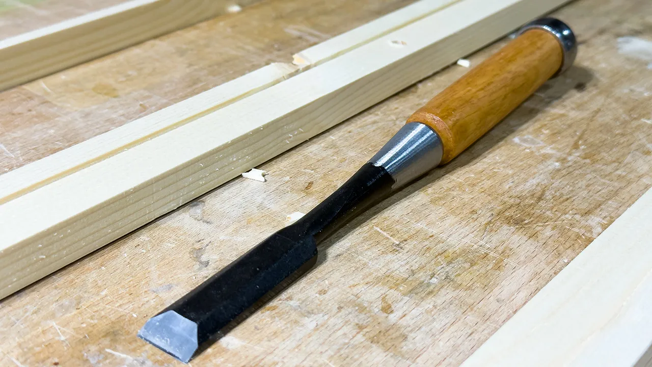
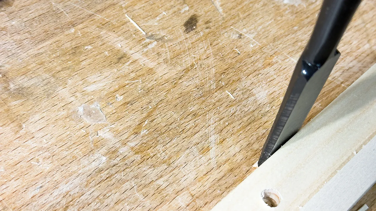
Chisel to remove Tabs
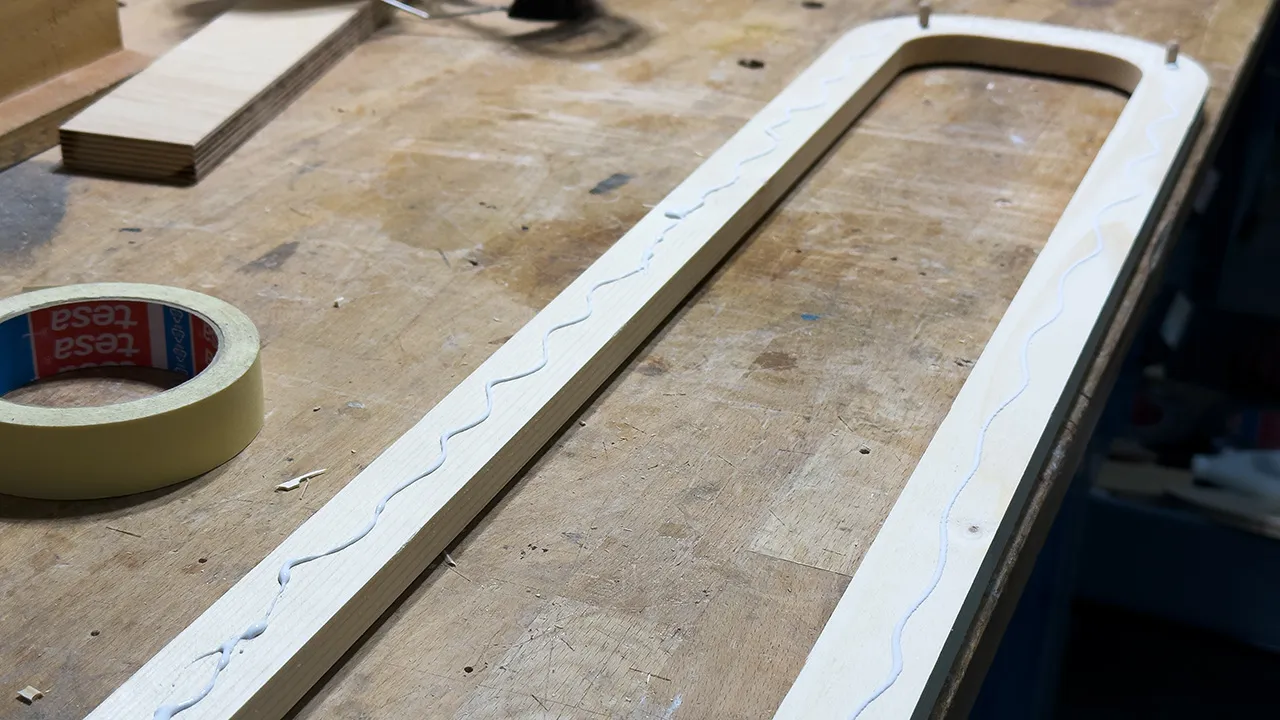
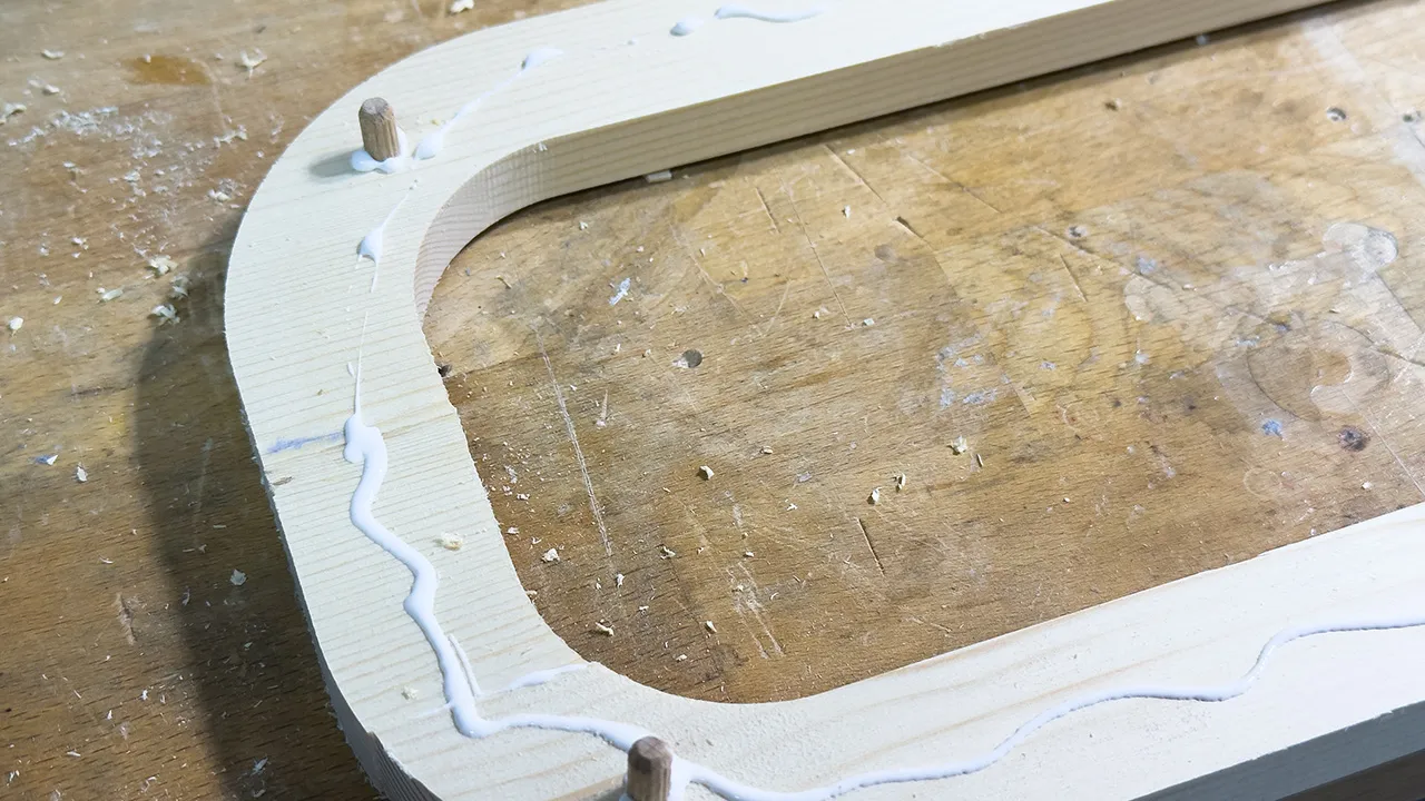
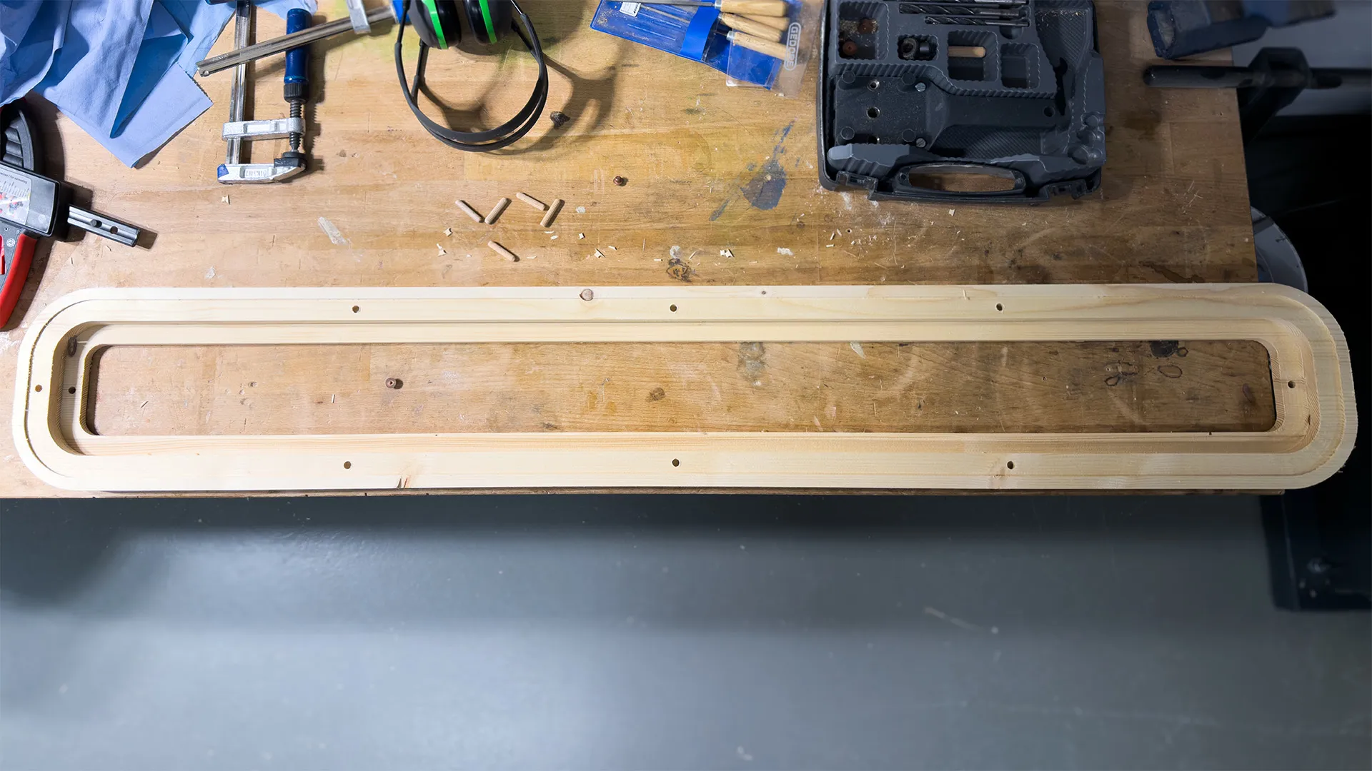
Glued Wood Parts
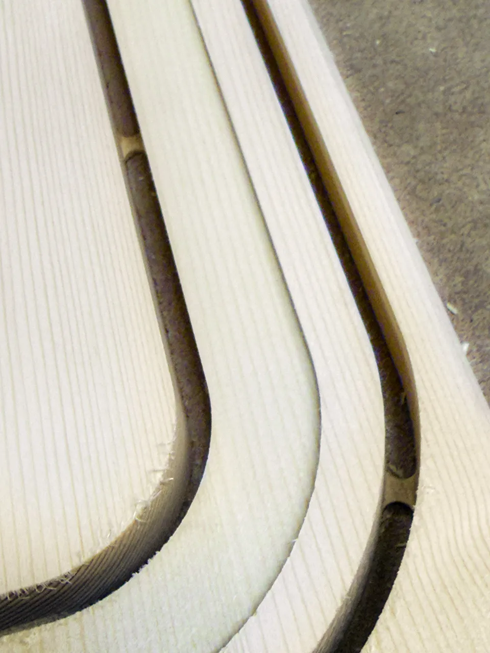
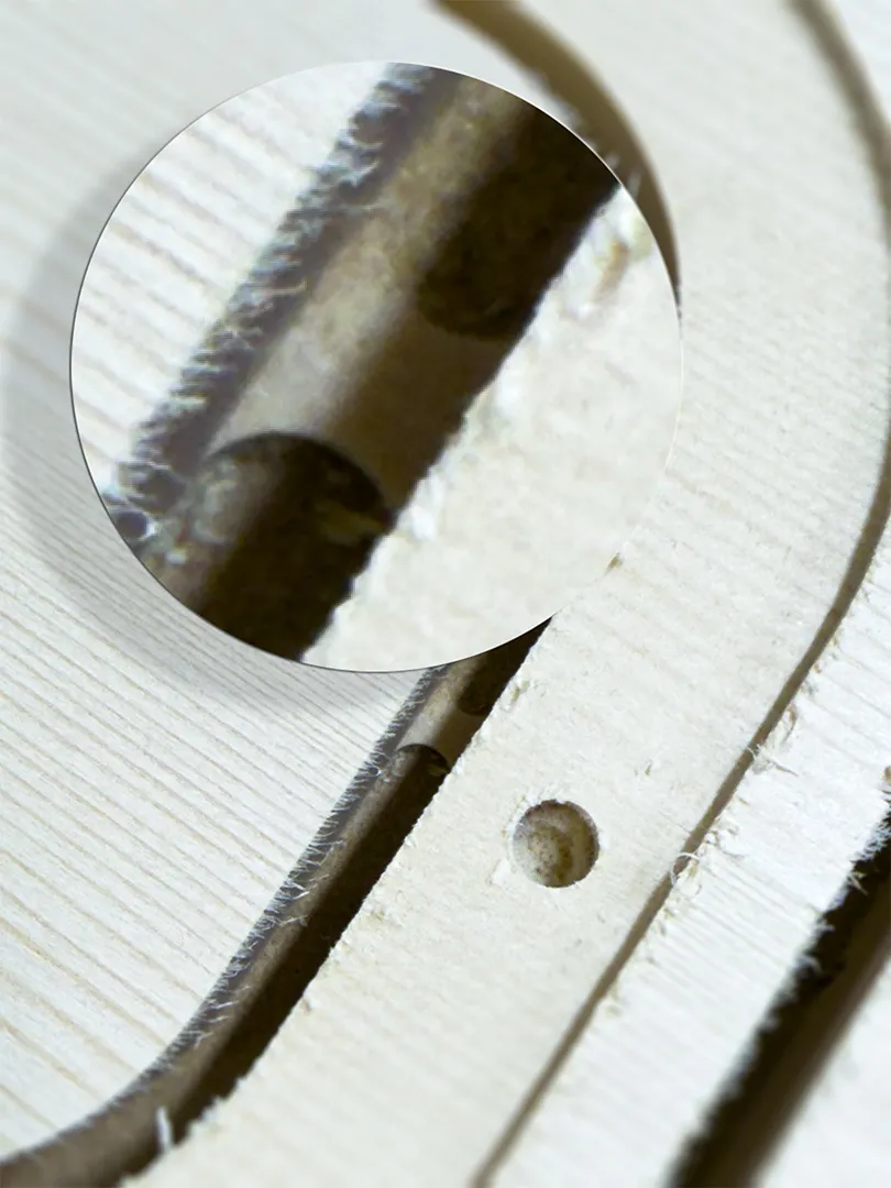
Leftover Tabs after Cutting
Final Lamp Shape
Ceiling Lamp
Since we had just moved and urgently needed a ceiling lamp for the walk-in closet, I decided to make one. The plan was a nearly rectangular ceiling lamp with rounded corners, featuring a frosted acrylic plate above the LED strip to diffuse the light.
For lighting, I am using an LED strip. This allows simple dimming and microcontroller control, occupies very little space, and produces minimal heat, which can be dissipated through the metal plate if necessary. The lamp was designed to measure around 1200 mm x 200 mm x 38 mm, keeping it flat against the ceiling. With this setup, all requirements for the lamp are met.

For this project, I used inexpensive spruce wood. In the future, I recommend using higher-quality wood, as spruce tends to splinter easily. Despite being widely available and cheap, it is not ideal for this kind of project.
Design
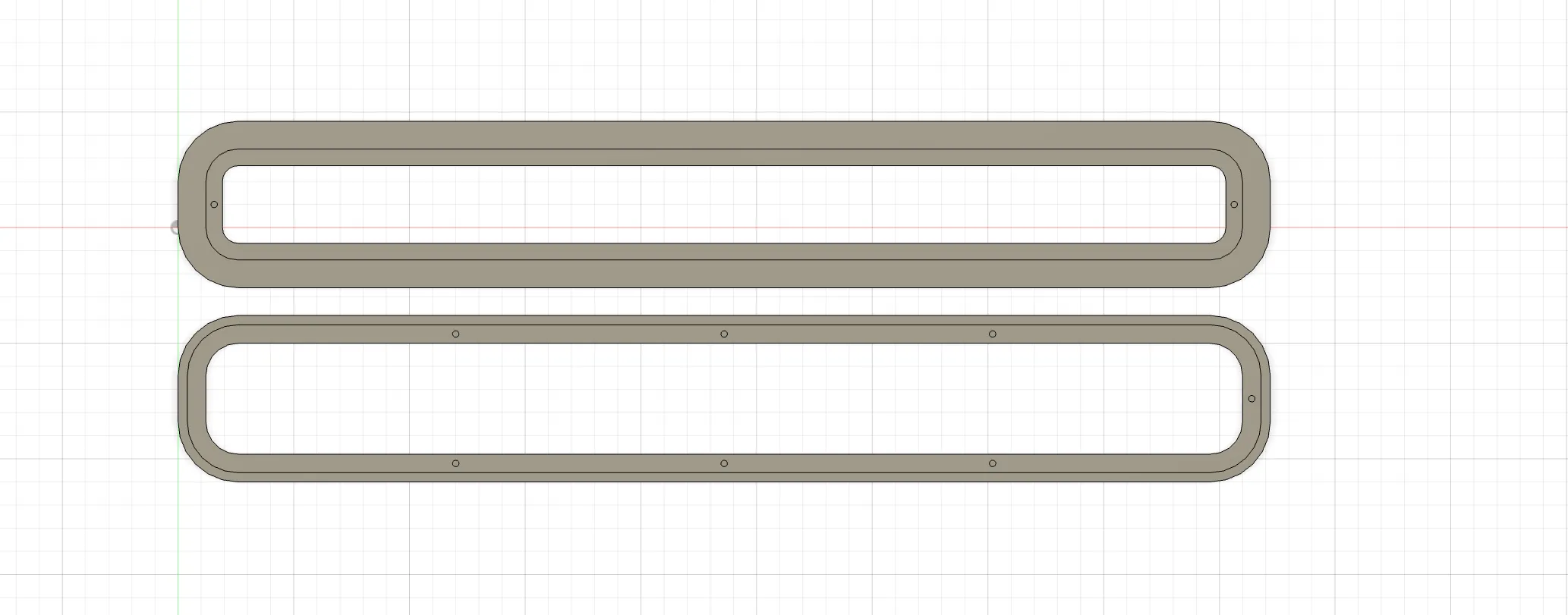
I designed the lamp in Houdini, keeping it fully parametric. This allows adjustments in the future if measurements change or if milling requires corrections. For example, the original design was slightly too large because I did not take the CNC offsets into account for screw fixing, so I quickly adjusted the file.
To make assembly and disassembly easy, I added threaded inserts with corresponding screws. These connect the metal plate to the wood and hold the acrylic plate in place. Thicknesses, offsets, and screw positions can all be modified parametrically.
1. Create the simple shape
Take a Cube and Bevel its edges.
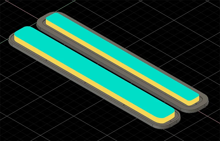
2. Make interior extrusions for metal and acrylic plates
Select the top faces and use Extrude with an inset to hollow out the object. Chain this action in a row to create several platforms. You can use the Front Group output to drive the next extrusion selection.
3. Add holes for threaded inserts
Use Tubes that represent the screw inserts. Use Copy Transform or Mirror to save some work by positioning multiple tubes at once. Use a Boolean to carve the tubes out of the original geometry.
Milling Preparation
To prepare for milling, I imported the design into Fusion 360. Here I ran into the first challenge: Fusion 360 does not support N-gons (polygons with more than four edges). My Houdini model had to be converted into a mesh with 3- or 4-sided polygons using the Divide SOP (Surface Operator) in Houdini. This caused some loss of clearly defined edges, but allowed the model to import into Fusion.
Unfortunately, this was not my only issue. Fusion also requires solid bodies for milling operations. Unlike polygon-based geometry in other software (for example Blender, 3ds Max, Rhino, and Maya), this type of 3D object is defined by volume rather than visible mesh segments. I tried converting the object inside Fusion 360, but even after converting, the faces could not be selected reliably. Because of this, I recreated the object in Fusion using a parametric sketch and extrusions. This then allowed me to select every edge and face for milling operations.
Milling Operations
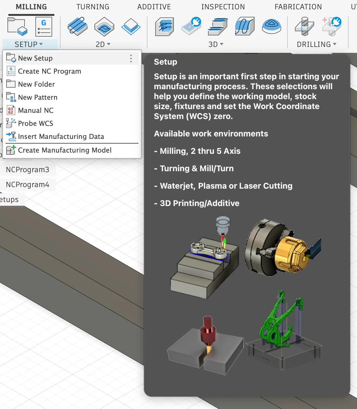
Create Milling Setup
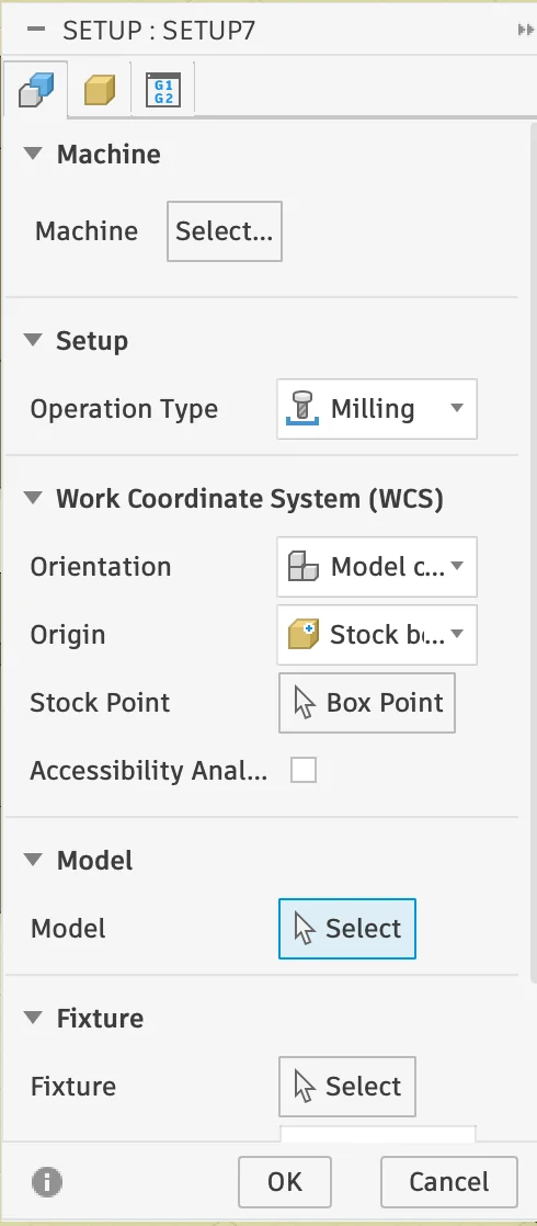
Switch to Fusion 360's Manufacturing workspace to prepare the milling setup for your object. Open Milling > Setup > New Setup to create a new job.
Under Model, select the 3D geometry you want to mill. At this stage, you can also choose a machine profile. In our lab, there is no suitable preset for the CNC, so this field can simply be left empty.
Once the setup is created, a new folder appears in the CAD browser on the right side. All machining operations will be added underneath it in order. It is also helpful to rename the setup or job immediately so the project stays clear and organized.
Milling Operations
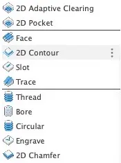
Fusion 360 offers many different machining operations for shaping a model. For this lamp housing, I only needed a small selection, but the Manufacturing workspace includes many more tools for both simple 2D cuts and more advanced 3D surface machining.
2D Operations: Face quickly levels the top of the stock, 2D Adaptive Clearing removes material efficiently while keeping tool engagement more constant, Slot cuts along the centerline of a slot, and Trace follows selected edges or sketch lines for details such as grooves or engraving.
3D Operations: 3D Adaptive Clearing is used as a roughing pass on more complex shapes, Horizontal detects and machines flat areas automatically, Parallel creates evenly spaced finishing passes across shallow surfaces, and Scallop follows sloped and vertical walls with a constant stepover for smoother curved finishes.
In practice, the workflow often starts with roughing operations to remove bulk material and continues with finer finishing passes to clean up details and improve the surface quality.
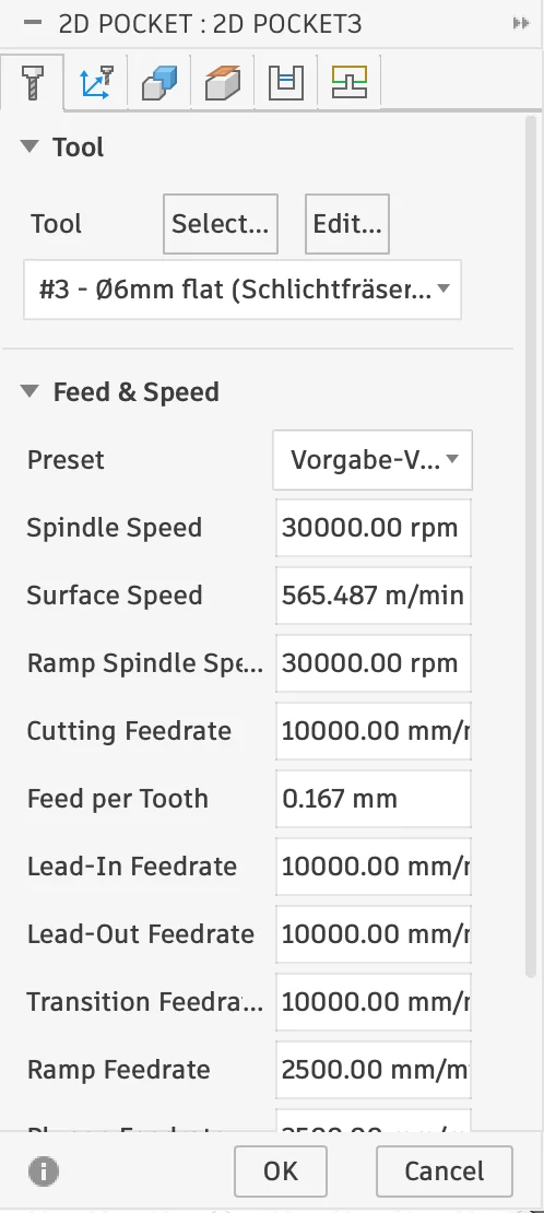
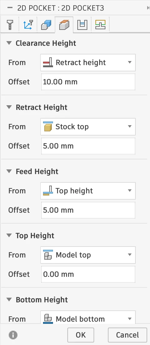
2D Pocket
Cuts out a recessed area. Start and end positions, as well as depth, are adjustable.
This operation is ideal for clearing material inside closed areas, for example recesses, cavities, or plate insets. In Fusion 360, the machining area can be selected from edges, sketches, or faces, depending on how the model is prepared.
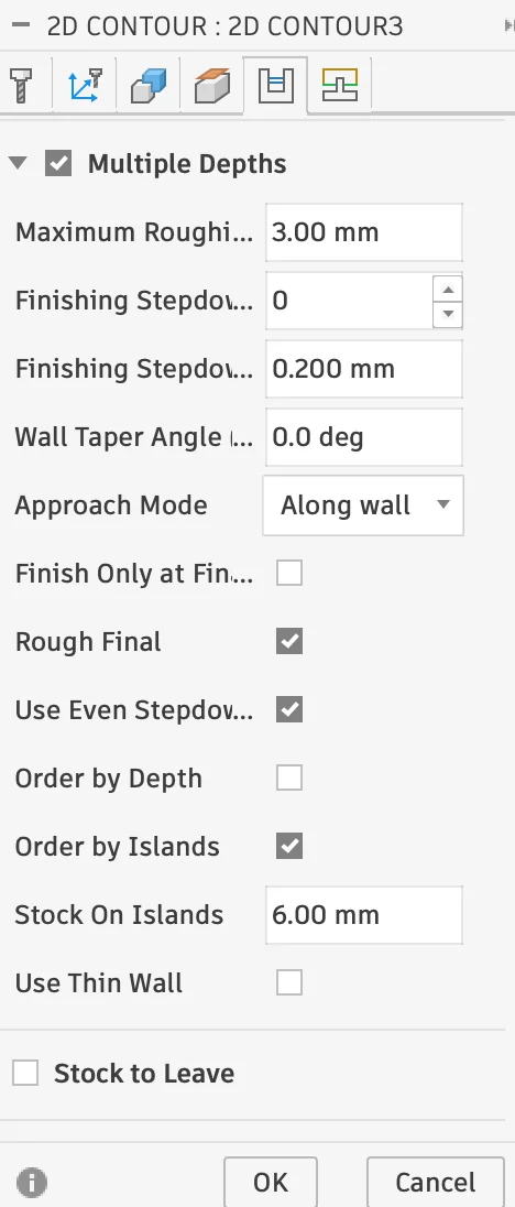
Important settings are the bottom height, stepdown, and whether the toolpath should only remove rest material from a previous pass. For simple flat recesses, 2D Pocket is a straightforward way to remove material layer by layer while keeping the geometry clean and predictable.
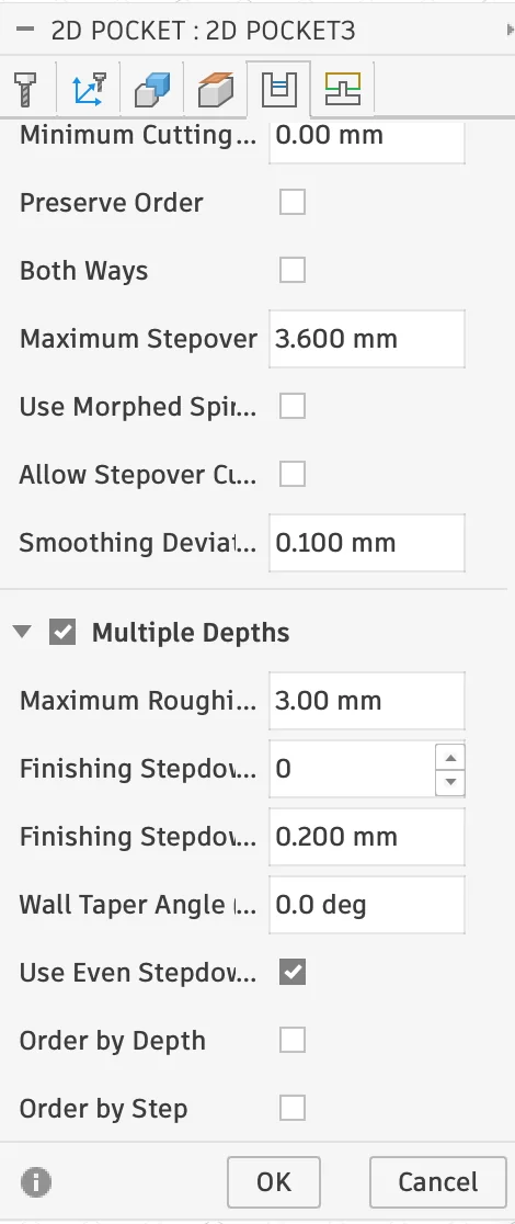
Settings: 6mm Diameter Cutter, 3mm even Steps
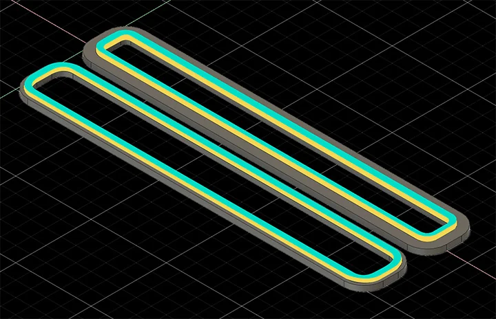
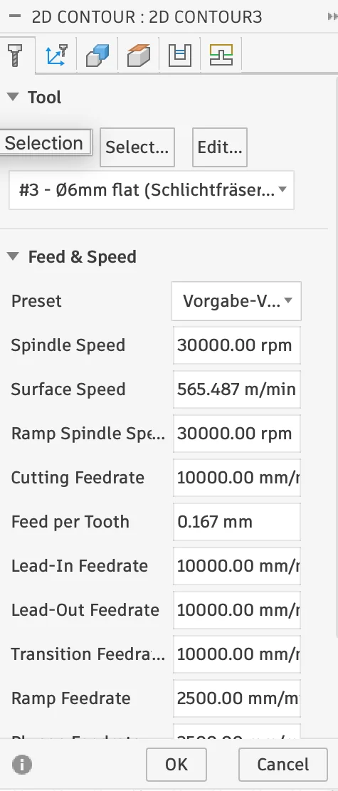
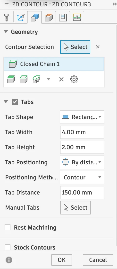
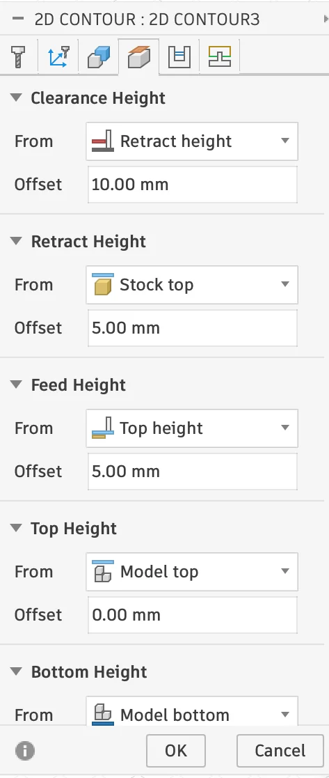
2D Contour
Cuts along a contour to separate parts from the material. Tabs are used to prevent the pieces from shifting during cutting. Start and end positions, depth, and tab placement are adjustable.
2D Contour is typically used for profiling the outside or inside boundary of a part. The selected edge or sketch defines where the cutter travels, and the cut direction can be flipped depending on whether the tool should machine inside or outside the contour.
For parts that need to stay fixed in the stock, tabs are especially important. Fusion also allows roughing passes, finishing passes, tangential extensions, and compensation settings, which makes this operation useful for both rough cutouts and more precise final passes.
Settings: 6mm Diameter Cutter, 3mm even Steps, 4mm Tab Width, 2mm Tab Height, 150mm Tab Distance
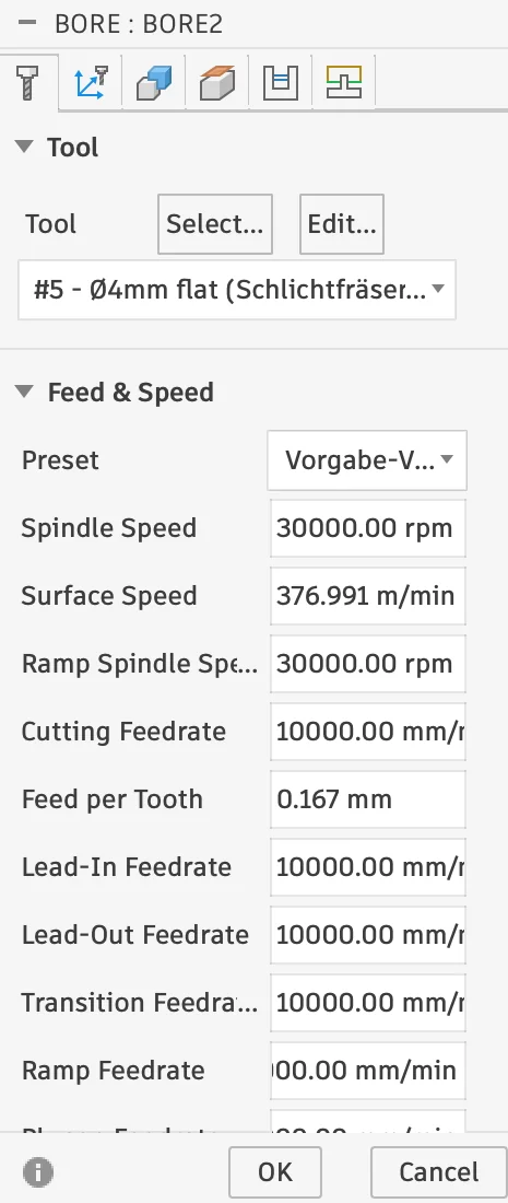
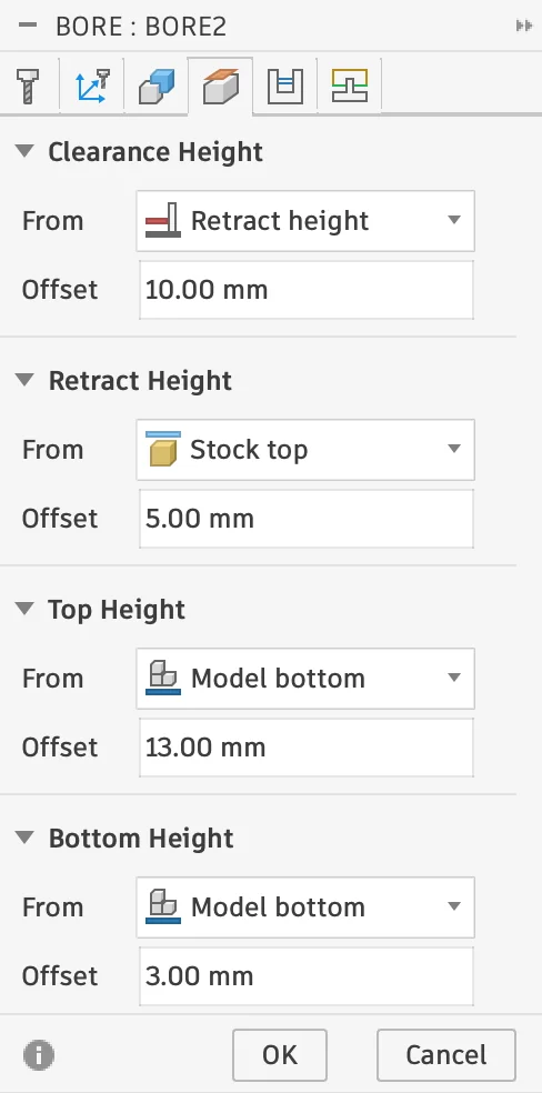
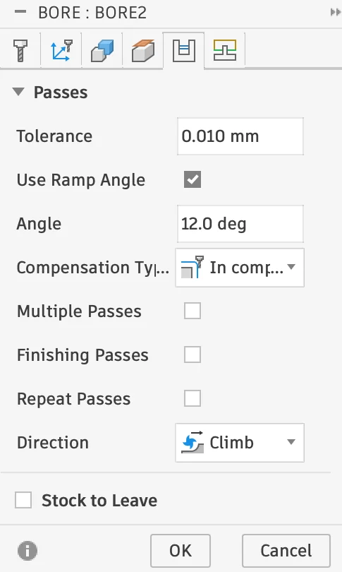
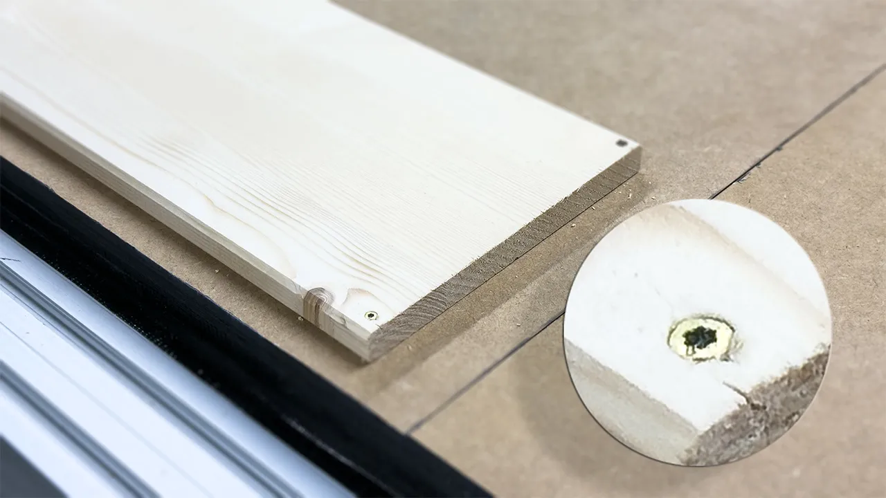
Bore
Creates a spiral-like cutting path to create holes in the material. Start and end positions and depth are adjustable.
This operation is useful for machining circular holes or bosses with a helical motion instead of plunging straight down. In Fusion 360, you can select cylindrical or tapered faces directly, and the heights are usually derived automatically from that geometry.
Important parameters include the pitch or ramp angle, optional multiple passes, and a finishing pass for cleaner walls. Compared with a simple circular move, Bore is often a more controlled and efficient strategy for accurately cutting holes.
Settings: 4mm Diameter Cutter, 12 Degree Spiral
This Bore operation creates the space where the threaded inserts will fit. The inserts will hold the screws for mounting the metal and acrylic plates.

Step depth is typically set to half the diameter of the cutter (for example, a 6 mm cutter -> 3 mm step depth). Enabling "Even Steps" prevents leftover small cuts.

Settings & Tools
Across all of the operations above, a few settings matter especially: the tool, the spindle speed, the feed rate, and the step depth. The tool defines the cutter geometry and diameter, which directly affects how small details can be machined and how much material can be removed per pass. Spindle speed describes how fast the cutter rotates, while feed rate controls how quickly the tool moves through the material. Step depth defines how deep each cutting layer goes before the next pass starts.
These values need to work together. If the spindle turns too fast while the feed rate is too low, the cutter may burn the material instead of cutting it cleanly. If the feed rate is too high or the step depth is too aggressive, the tool can chatter, leave rough edges, or even break. Choosing balanced values is therefore just as important as choosing the correct toolpath.
For the tools, I used a configuration file with all available cutters in the lab already set up. This made it easier to use the right cutter profiles and pre-tested parameters directly inside Fusion 360. If no such library is available, custom values for the tool, spindle speed, and feed rate can also be defined manually in the tool settings.
When you do not already have a tool library with suitable feeds and speeds, the Fablab Speed and Feeds Calculator is a very helpful starting point.
For more details on how different values behaved on our machine, along with documented test results from our lab, I also linked the documentation on our group page.
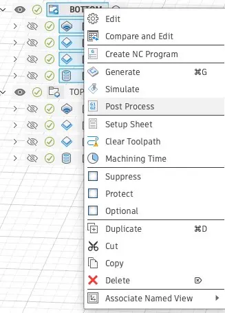
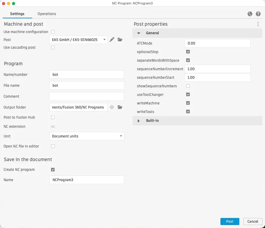
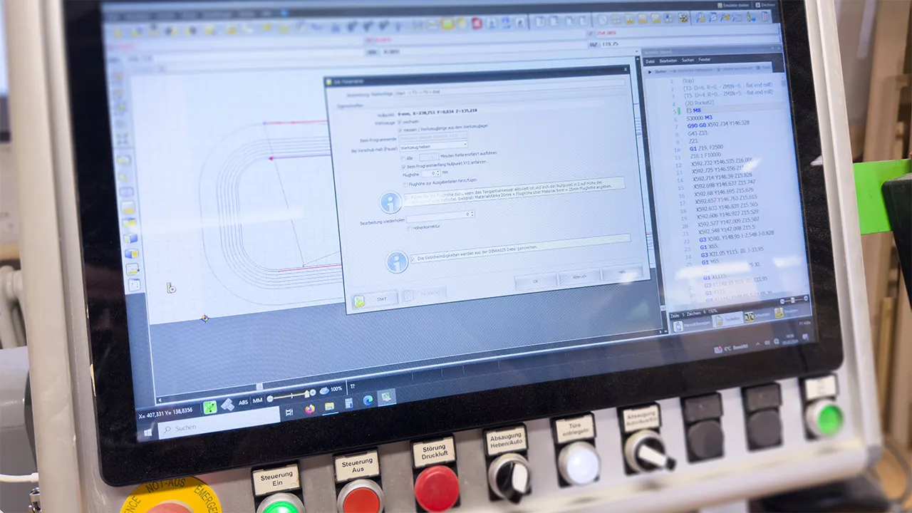
NC File Export
Once all operations were defined, I exported the NC file by right-clicking the created milling setup and selecting "Post Process". NC files describe the CNC toolpath as coordinates and simple commands, such as turning the vacuum on (M8) or changing tools (described by a T followed by the tool ID of the CNC).
Fusion does not automatically add some commands (for example, vacuum start), so these must be added manually at the start of the program.
Milling
I transferred the NC file to our CNC machine, an EAS Versatil 2500. The vacuum system was engaged, and the board was secured using screws along the edges and a few in the middle cutout. I reviewed the safety procedures and made sure I knew the locations of the emergency stops and fire extinguishers. Once all precautions were in place, I started the milling process.
Before starting a CNC job, the material, tool, collet, spindle, workholding, sacrificial board, and CAM setup must be checked carefully. The workpiece has to be fixed securely, and the toolpath should be simulated or verified before running the machine. The zero point, cutting depth, spindle speed, feed rate, and tool diameter must match the CAM settings.
During operation, safety glasses and hearing protection must be worn. Loose clothing, long hair, hands, and tools must be kept away from moving parts and the spindle. The dust extraction system must be switched on, and the user should stay near the machine while the job is running.
The machine must be stopped immediately if unusual noise, excessive vibration, smoke, a loose workpiece, tool breakage, or any other unsafe condition occurs. The emergency stop button must be known and accessible at all times.
After machining, wait until the spindle has completely stopped before removing parts, tools, or chips.
Post-Processing
After milling, the board had to be carefully removed from the bed. Tabs used to secure the lamp during cutting had to be cut first in the center, allowing the main piece to be freed. The remaining edges of the tabs could be easily trimmed with a sharp chisel. Afterwards, I smoothed it using a router.
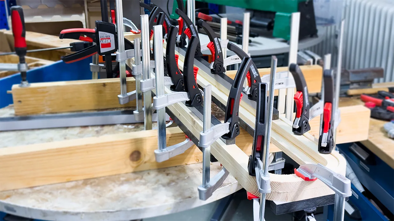
Because a total lamp height of 38 mm could be challenging for the cutter, I milled it in two parts. The boards were then joined using dowel holes and a layer of wood glue. Multiple clamps ensured the pieces dried flat without gaps.
In the coming weeks, the electronics, acrylic, and metal plate will be added to complete the lamp and give it its final finish. Stay tuned!