

Software & Tools
Altium Designer
Schematic capture, PCB layout and routing, design rule checking.
26.3.0
Education

LPKF Circuit Pro
Gerber import, layer mapping, process planning, and toolpath generation for PCB milling.
2.5 PM
Lab machine software license
Arduino IDE
Sketch editing, board package management, uploading, and serial monitoring.
Version 2.3.7
Open Source (GNU AGPLv3)


PCB Design
The lamp will include an RGB LED strip. This means the LEDs can display any color and, more importantly, can also be dimmed. The first part is more of a nice-to-have than something truly necessary, but dimming is a very useful feature that would be especially important in our bedroom.
Accordingly, I wanted to use a component that makes dimming the lamp possible in an intuitive way. A potentiometer is a perfect fit here, since the rotary motion also connects well to existing mental models. At the same time, having a button to switch between modes such as RGB control and, above all, to turn the lamp off completely would also be very useful.
For this week, I will initially use the onboard LED of my ESP32, but with the help of this foundation the same functionality can later be transferred 1:1 to the ceiling lamp.
Because I would like to design my controller with the future use case in mind, I also want to go a little beyond the basic functions for controlling the lamp and include a display. This should, for example, make it possible to show and adjust the room temperature or display other status messages. This is another reason why the button is important, since I now really need a way to skip through the functions. In theory, turning the lamp off could also have been achieved by checking whether the potentiometer is pulled to 0.
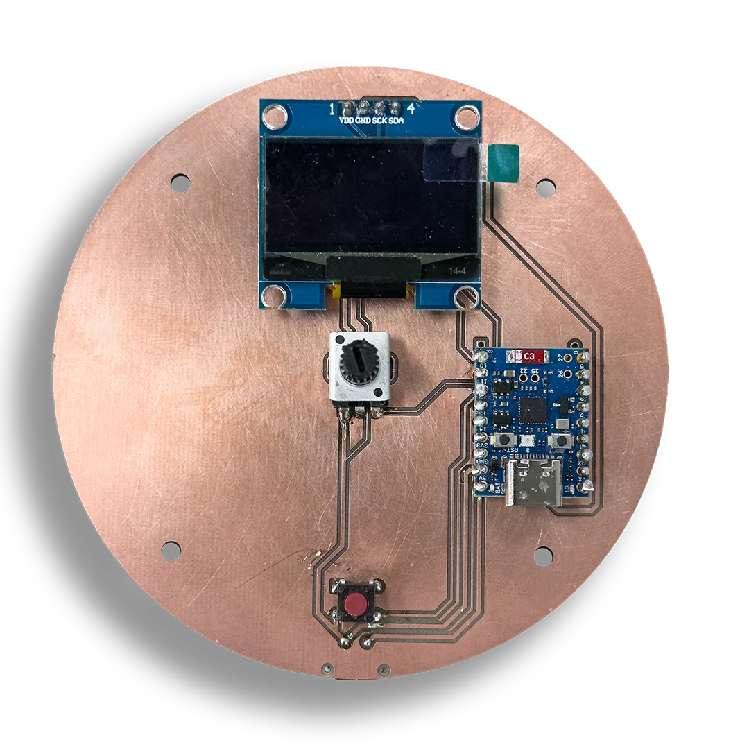
Once the requirements were defined, the PCB design itself was largely straightforward. I use an external USB port as the power input, connect the 5V line to the 5V pin of the ESP, and then route the onboard-converted 3V3 to the sensors and the display.
The button is connected to GND and sends a LOW signal as soon as it is pressed. The display uses a simple I2C connection and runs on 3V3, GND, SDA, and SCL. The potentiometer is also powered with 3V3 and GND and uses an analog output.
That analog pin, together with SDA and SCL, are some of the most important pins in this design. As always, it is important to check the datasheet or ESP board documentation to see which pins are suitable and, in the case of I2C, which ones may already be intended for that function. Since the potentiometer sends an analog signal, not every pin is a valid choice here either.


Now everything is ready for export. Go to PCB > File > Fabrication Outputs > Gerber Files. A pop-up appears. Only the necessary layers need to be selected. For example, I do not need silkscreens for simple milling with the LPKF. Silkscreens usually contain details like designators on the PCB - indicating which parts go where and therefore an idea of which exact components are used. This is helpful for large product chains and debugging, but for simple prototyping purposes not necessary. The exported file(s) can now be placed on a USB drive. To ensure everything was exported correctly, Altium has an internal CAM viewer, but there are also external options such as Altium Viewer and many more.

For single-sided boards and work without vias, it is especially important to place THT (through-hole) components on the bottom side, otherwise they cannot be soldered properly, or only with difficulty, as you can see below. By placing them on the bottom layer, Altium mirrors them automatically so they can later be mounted on a single-sided PCB without problems. Otherwise, the solder joints end up inverted, which causes problems for most wire connections. To work around this issue in my case, I soldered on the same layer on which the THT components were placed. In hindsight, this design should either have been milled on a double-sided PCB and connected with vias, or designed from the beginning with mirrored THT components.
PCB Production
PCB Milling
Take the exported files and put them into your PCB machine. Refer to that documentation for a more detailed view of the PCB milling process.
PCB Soldering
After the milling is done, you may now sand your board down and clean it with isopropanol. Then you can start attaching your components to the board. As usual, do not forget to check that the connections work properly with a multimeter. When everything looks fine, we can go to the next step and flash the code.
PCB Programming
Reading the Potentiometer
A potentiometer acts as a variable resistor. By turning the knob, the resistance ratio between its pins changes, which results in a different analog voltage at the signal pin.
The microcontroller reads this changing analog value and converts it into a number range that can be used in code. In this project, that changing reading later becomes the basis for dimming the lamp and adjusting other interface values in a direct and intuitive way.
Writing the code
As the sketch combines display setup, button handling, timeout logic, and multiple control states, I used AI to generate a first structured baseline and then adapted it to fit this controller.
The code uses FastLED to control the onboard RGB LED, Wire to initialize the I2C bus, and U8g2lib to drive the small OLED display. Together, these libraries cover LED output, display communication, and the visual interface of the controller.
Structurally, the sketch follows a small state-based logic. A mode enum switches between hue and brightness control, while separate state variables track whether the LED is enabled, whether the display is awake, the current hue and brightness values, and the timing for inactivity and button presses. The potentiometer is read continuously and smoothed over several samples, a short button press either wakes the display or switches modes, and a long press toggles the LED on and off.
#include <FastLED.h>
#include <Wire.h>
#include <U8g2lib.h>

// --- PINS ------------------------------------------------------
#define NUM_LEDS    1
#define DATA_PIN    8
#define POTI_PIN    4
#define BUTTON_PIN  12
#define SDA_PIN     11
#define SCL_PIN     10

// --- DISPLAY ---------------------------------------------------
U8G2_SSD1306_128X64_NONAME_F_HW_I2C u8g2(U8G2_R0, U8X8_PIN_NONE);

// --- LED -------------------------------------------------------
CRGB leds[NUM_LEDS];

// --- SMOOTHING -------------------------------------------------
#define SMOOTHING_SAMPLES 10
int  readings[SMOOTHING_SAMPLES];
int  readIndex   = 0;
int  smoothTotal = 0;

// --- MODES -----------------------------------------------------
enum Mode { MODE_HUE, MODE_BRIGHTNESS };
Mode currentMode = MODE_HUE;

// --- STATE -----------------------------------------------------
bool    ledEnabled    = true;
bool    displayOn     = true;
uint8_t hue           = 0;
uint8_t brightness    = 128;
int     lastPotiValue = -1;

// --- DISPLAY TIMEOUT -------------------------------------------
#define DISPLAY_TIMEOUT_MS 5000
unsigned long lastActivityTime = 0;

// --- BUTTON ----------------------------------------------------
bool          lastButtonState  = HIGH;
unsigned long buttonPressTime  = 0;
bool          longPressHandled = false;

// ---------------------------------------------------------------

void wakeDisplay() {
  lastActivityTime = millis();
  if (!displayOn) {
    displayOn = true;
    u8g2.setPowerSave(0);
    Serial.println("[Display] Wake up");
  }
}

void updateLED() {
  if (!ledEnabled) {
    leds[0] = CRGB::Black;
  } else {
    leds[0] = CHSV(hue, 255, brightness);
  }
  FastLED.show();
}

void drawDisplay() {
  if (!displayOn) return;

  int  displayValue = (currentMode == MODE_HUE) ? hue : brightness;
  int  barWidth     = map(displayValue, 0, 255, 0, 118);
  int  percent      = map(displayValue, 0, 255, 0, 100);

  u8g2.clearBuffer();

  // -- Mode label --
  u8g2.setFont(u8g2_font_6x10_tf);
  if (currentMode == MODE_HUE) {
    u8g2.drawStr(0, 10, "[ HUE ]   Brightness");
  } else {
    u8g2.drawStr(0, 10, "  Hue   [ BRIGHTNESS ]");
  }

  // -- Separator line --
  u8g2.drawHLine(0, 13, 128);

  // -- Large value --
  u8g2.setFont(u8g2_font_logisoso32_tf);
  u8g2.setCursor(0, 50);
  u8g2.print(percent);
  u8g2.print("%");

  // -- LED status --
  u8g2.setFont(u8g2_font_6x10_tf);
  u8g2.drawStr(100, 50, ledEnabled ? "ON" : "OFF");

  // -- Bar --
  u8g2.drawFrame(0, 54, 128, 10);
  if (barWidth > 0) {
    u8g2.drawBox(1, 55, barWidth, 8);
  }

  u8g2.sendBuffer();
}

// ---------------------------------------------------------------

void setup() {
  Serial.begin(115200);
  delay(500);
  Serial.println("=== ESP32-H2 Start ===");

  // ADC
  analogReadResolution(12);
  analogSetAttenuation(ADC_11db);
  for (int i = 0; i < SMOOTHING_SAMPLES; i++) readings[i] = 0;

  // Button
  pinMode(BUTTON_PIN, INPUT_PULLUP);

  // FastLED
  FastLED.addLeds<NEOPIXEL, DATA_PIN>(leds, NUM_LEDS);

  // Display
  Wire.begin(SDA_PIN, SCL_PIN);
  u8g2.begin();
  u8g2.setPowerSave(0);

  lastActivityTime = millis();
  updateLED();
  drawDisplay();

  Serial.println("Mode: HUE | LED: ON | Display: ON");
}

// ---------------------------------------------------------------

void loop() {

  // == POTI =====================================================
  int raw = analogRead(POTI_PIN);
  smoothTotal -= readings[readIndex];
  readings[readIndex] = raw;
  smoothTotal += readings[readIndex];
  readIndex = (readIndex + 1) % SMOOTHING_SAMPLES;

  int potiValue = constrain(map(smoothTotal / SMOOTHING_SAMPLES, 0, 3504, 0, 255), 0, 255);

  if (abs(potiValue - lastPotiValue) >= 3) {
    wakeDisplay();
    lastPotiValue = potiValue;

    if (currentMode == MODE_HUE) {
      hue = potiValue;
      Serial.print("[Poti] Hue: ");
      Serial.print(map(hue, 0, 255, 0, 100));
      Serial.println("%");
    } else {
      brightness = potiValue;
      Serial.print("[Poti] Brightness: ");
      Serial.print(map(brightness, 0, 255, 0, 100));
      Serial.println("%");
    }

    updateLED();
    drawDisplay();
  }

  // == BUTTON ===================================================
  bool buttonState = digitalRead(BUTTON_PIN);

  // Edge: pressed
  if (buttonState == LOW && lastButtonState == HIGH) {
    buttonPressTime  = millis();
    longPressHandled = false;
  }

  // Hold: detect long press (>3 s)
  if (buttonState == LOW && !longPressHandled) {
    if (millis() - buttonPressTime >= 3000) {
      ledEnabled       = !ledEnabled;
      longPressHandled = true;
      wakeDisplay();
      updateLED();
      drawDisplay();
      Serial.print("[Button] Long Press -> LED: ");
      Serial.println(ledEnabled ? "ON" : "OFF");
    }
  }

  // Edge: released
  if (buttonState == HIGH && lastButtonState == LOW) {
    if (!longPressHandled) {
      if (!displayOn) {
        // Display was off -> only wake it
        wakeDisplay();
        drawDisplay();
        Serial.println("[Button] Short Press -> Display wake");
      } else {
        // Switch mode
        currentMode = (currentMode == MODE_HUE) ? MODE_BRIGHTNESS : MODE_HUE;
        wakeDisplay();
        drawDisplay();
        Serial.print("[Button] Short Press -> Mode: ");
        Serial.println(currentMode == MODE_HUE ? "HUE" : "BRIGHTNESS");
      }
    }
  }

  lastButtonState = buttonState;

  // == DISPLAY TIMEOUT ==========================================
  if (displayOn && millis() - lastActivityTime >= DISPLAY_TIMEOUT_MS) {
    displayOn = false;
    u8g2.setPowerSave(1);
    Serial.println("[Display] Standby");
  }

  delay(10);
}