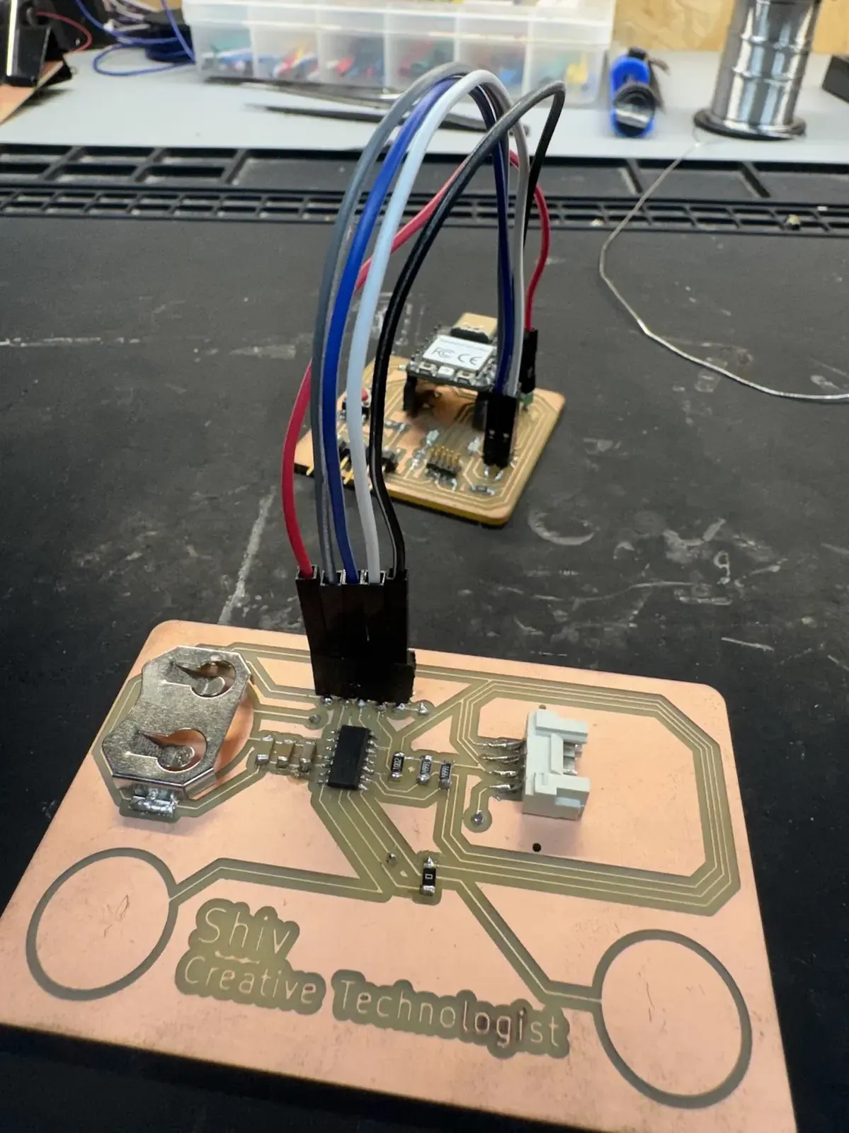
Overview
This week's assignment: add a sensor to a microcontroller board you've designed, and read it. I didn't need an extra component, the capacitive touch pads are already baked into my PCB business card from Week 8. Two bare copper circles at the bottom corners. When you hold both at once, the OLED scrolls through a set of personal facts. Let go, and it shows: Hold Me.
The sensing is analog-ish, floating, and environment-dependent. Getting reliable readings out of two unshielded copper pads on a board with no working USB serial meant building a calibration workflow entirely on the OLED display. This page documents the physical principles, the calibration process, and the code.
The group assignment, probing an input device's analog levels and digital signals, is reflected on below and documented on the group work page. The OLED output device is documented in Week 10: Output Devices →
"The raw count is a proxy for capacitance, which is a proxy for contact area, which is a proxy for intention."
The Board
Designed in Week 6 and built in Week 8. The touch pads are a design feature, not an addition, two exposed copper circles connected by trace directly to GPIO pins on the ATSAMD11C14A.
- ATSAMD11C14A — ARM Cortex-M0+, SOIC-14. Pins PA04 (Arduino 4) and PA05 (Arduino 5) connect to the left and right touch pads.
- Touch pads — bare copper circles. No component, no soldermask, no pull-up resistor. Just exposed trace.
- OLED header — JST connector: VCC, GND, SDA (pin 8), SCL (pin 9). Used for calibration output as well as final display.
- CR2032 holder — Keystone 3034. Powers standalone once programmed.
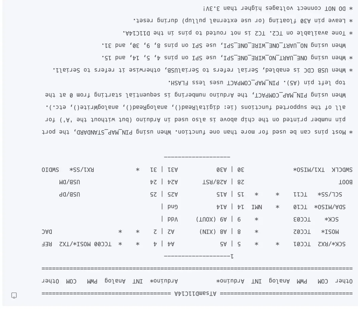
ATSAMD11C14A pinout. Touch pads sit on A4 and A5. Pins 8 (SDA) and 9 (SCL) carry the OLED, getting those to route correctly required a specific Serial Config change documented in Week 10 →
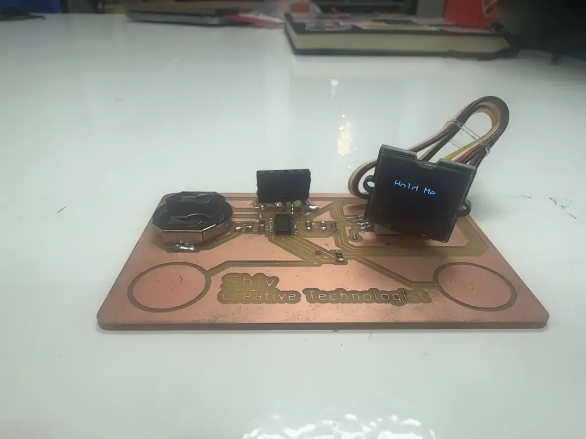
Board with OLED connected. The touch pads are the two bare copper circles at the bottom corners, no component, just exposed trace.
Physical Principles: How Capacitive Touch Works
Your finger is a conductor. When it contacts an exposed copper pad, it forms a capacitor, two conductors (finger + pad) separated by a dielectric (skin + air). That capacitance is tiny, in the range of picofarads, but it's measurable using nothing but a GPIO pin and the chip's internal pull-up resistor.
Why Not Just digitalRead()?
Copper pads without debounce or pull-up
resistors are floating capacitive sensors, not
digital switches. A raw
digitalRead() produces flickering
touch state and unreliable triggering. Several
environmental factors all feed into the reading
simultaneously:
- Humidity — changes the dielectric between finger and pad
- Grounding — whether you're on rubber, barefoot, touching metal
- Body capacitance — varies person to person: hand size, contact area, rings
- Laptop charger noise — switching supply noise couples into unshielded traces
Charge-time measurement reads a continuous value rather than a binary threshold. Environmental drift shifts the number, but the gap between untouched (~3–5) and touched (~20–140) stays large enough to threshold reliably.
The Charge-Time Method
The GPIO pin acts as both the charge source and the sensor:
- Discharge: Set pin OUTPUT LOW. Drains any charge on the pad to ground.
- Switch to INPUT_PULLUP: The internal pull-up (~30–50kΩ) begins charging the pad capacitance.
- Count: Loop until the pin reads HIGH, until voltage crosses ~0.7×VCC.
- Read: Count is proportional to τ = R × C. More capacitance (finger) → longer charge time → higher count.
Think of it like filling a bucket with a fixed-rate tap. Small bucket (no finger) fills fast. Big bucket (finger adds capacitance) fills slow. The count tells you the bucket size.
Calibration: Finding the Right Threshold
Before I could set a touch threshold, I needed to know what the raw counts actually looked like on this specific board in real conditions. USB serial never enumerated correctly on the ATSAMD11 with NO_BOOTLOADER, Serial Monitor stayed blank throughout the project. So I printed live counts directly to the OLED.
The OLED as Debugger
I ran a calibration sketch that wrote the raw count from each pad live to the display:
// Calibration sketch, live counts on OLED
u8g2.clearBuffer();
u8g2.setCursor(31, 30);
u8g2.print("L:"); u8g2.print(left);
u8g2.setCursor(31, 45);
u8g2.print("R:"); u8g2.print(right);
u8g2.sendBuffer();
With this running, I could watch the numbers change in real time as I touched and released each pad, with bare fingertip, full palm, through a sleeve, with the charger plugged in. The display updated every 20ms, fast enough to see the count respond to contact.
Measured Values
Across multiple conditions and people:
- No touch (noise floor): Left ~3–5, Right ~3–5
- Light fingertip graze: Left ~18–35, Right ~20–40
- Full pad contact: Left ~80–140, Right ~70–120
The gap between noise (~5) and a real touch (~20+) is large and consistent across conditions. Threshold set at 10 — comfortably above noise, triggered by even a light graze. Both pads must exceed threshold simultaneously to prevent accidental triggers from setting the board down.
How the Code Works
readTouch() — The Core Sensing Function
Takes a pin number, runs the charge-discharge cycle, returns a count. The cap of 300 prevents an infinite loop if a wire is disconnected or a pad is shorted to VCC.
long readTouch(int pin) {
  pinMode(pin, OUTPUT);
  digitalWrite(pin, LOW);  // discharge pad to ground
  delay(1);

  pinMode(pin, INPUT_PULLUP); // start charging via internal ~40kΩ pull-up

  long count = 0;
  while (digitalRead(pin) == LOW && count < 300) {
    count++; // count loops until voltage crosses logic threshold
  }
  return count;
}
Detection Logic — Both Pads Required
A single-pad trigger is too easy to hit accidentally. Requiring both pads simultaneously changes the interaction from a tap to a deliberate two-hand hold — the card held between your palms.
long left  = readTouch(TOUCH_LEFT);   // pin 4
long right = readTouch(TOUCH_RIGHT);  // pin 5

bool touched = (left > 10) && (right > 10);
The Scrolling Marquee
When touched, the OLED draws a string at
xPos and decrements
xPos each frame. The bounds 31 and
95 are the left and right edges of the Grove
OLED's visible crop window — the SSD1306
operates a 128×64 framebuffer but only X:31→95
is physically visible on the 64×48 panel. Full
explanation in Week 10: Output Devices →
if (touched) {
  const char* message = facts[currentFact];
  u8g2.drawStr(xPos, 40, message);

  xPos -= 14; // 14px per frame at 20ms delay

  int textWidth = strlen(message) * 6; // 6x12 font: 6px per char

  if (xPos < -textWidth + 31) { // text has exited left edge of visible window
    currentFact++;
    if (currentFact >= factCount) currentFact = 0;
    xPos = 95; // reset to right edge of visible window
  }
} else {
  u8g2.drawStr(40, 40, "Hold Me");
}
u8g2.sendBuffer();
delay(20);
Full Source Code
#include <Arduino.h>
#include <U8g2lib.h>

U8G2_SSD1306_128X64_NONAME_F_SW_I2C u8g2(
  U8G2_R0,
  /* clock=*/ 9,
  /* data=*/ 8,
  /* reset=*/ U8X8_PIN_NONE
);

#define TOUCH_LEFT  4
#define TOUCH_RIGHT 5

const char* facts[] = {
  "Loves Gilda",
  "New To BCN",
  "From India",
  "FAB LAB Noob",
  "Loves Emotional Design",
  "Built This Board with sweat blood and tears",
  "Created Whiff",
  "Has Congenital Anosmia",
  "She/ Her/ A11y"
};

const int factCount = 8; // note: 9 strings, 8 cycle — "She/Her/A11y" unreachable (known bug)

int currentFact = 0;
int xPos = 95;

long readTouch(int pin) {
  pinMode(pin, OUTPUT);
  digitalWrite(pin, LOW);
  delay(1);
  pinMode(pin, INPUT_PULLUP);
  long count = 0;
  while (digitalRead(pin) == LOW && count < 300) count++;
  return count;
}

void setup() {
  delay(1000);
  u8g2.begin();
  u8g2.setFont(u8g2_font_6x12_tf);
}

void loop() {
  long left  = readTouch(TOUCH_LEFT);
  long right = readTouch(TOUCH_RIGHT);
  bool touched = (left > 10) && (right > 10);

  u8g2.clearBuffer();
  if (touched) {
    const char* message = facts[currentFact];
    u8g2.drawStr(xPos, 40, message);
    xPos -= 14;
    int textWidth = strlen(message) * 6;
    if (xPos < -textWidth + 31) {
      currentFact++;
      if (currentFact >= factCount) currentFact = 0;
      xPos = 95;
    }
  } else {
    u8g2.drawStr(40, 40, "Hold Me");
  }
  u8g2.sendBuffer();
  delay(20);
}
Demo
Both pads held, OLED scrolling through personal facts. Release returns to "Hold Me."
Problems & Fixes
1. digitalRead() — flickering, unreliable UI
The first attempt used
digitalRead() with a threshold.
Touch state flickered, triggered inconsistently,
and caused the UI to blink. Copper pads are
floating capacitive sensors, not buttons, binary
reads can't handle environmental drift. Fix:
charge-time measurement. A continuous count
robust to drift; the gap between noise and touch
stays large regardless of charger noise or
humidity.
2. USB serial never worked — no way to print debug values
USB CDC didn't enumerate on ATSAMD11 with NO_BOOTLOADER. Serial Monitor stayed blank the entire project. This would have been the expected calibration path, print counts, observe, set threshold. Fix: the OLED became the debugging surface. Ended up being faster: real hardware, real time, no driver indirection.
3. factCount = 8 with 9 facts, last fact unreachable
The array has 9 strings but
factCount = 8, so "She/ Her/ A11y"
never displays, the cycle wraps to 0 before
reaching index 8. This is a known bug in the
current code, documented here rather than
silently fixed. The board still demonstrates the
full concept correctly across the 8 cycling
facts.
Group Assignment: Analog Levels vs Digital Signals
The group brief was to probe an input device's analog levels and digital signals , to actually look at the difference between the continuous value a sensor produces and the on/off decision a microcontroller makes from it. The group's captures and notes are on the group work page, linked in the sidebar.
My own board turned out to be a small, living
example of exactly that distinction, which is what I
keep coming back to. The touch pad doesn't hand the
chip a clean 0 or 1 — it hands it a raw charge-time
count that drifts with humidity, grounding,
and even the laptop charger humming nearby. That's
the analog level: a smear of numbers, not a switch.
The digital signal — touched — only
exists because I drew a threshold line through that
smear and said "above this, it's a yes." Probing the
count live on the OLED was me watching the analog
reality before it got flattened into a bit.
That reframed what a "sensor reading" even is. The digital signal feels like the truth, but it's the interpretation; the analog level is the truth, messy and continuous. Every reliable input device is really a good decision about where to put the threshold — and you can only place it well once you've looked at the analog levels underneath, which is the whole point of the group probing exercise.
Design Files & Source Code
Board designed in Week 6: Electronics Design and produced in Week 8: Electronics Production. OLED output device documentation — setup, framebuffer crop, rendering — in Week 10: Output Devices →
- touch-facts.ino — full Arduino sketch (source code)
- visitingcardnew.kicad_pcb — board design (KiCad), from Week 8
Arduino settings:
- Board: Generic D11C14A (Fab SAM core)
- Programmer: CMSIS-DAP via Quentorres
- Bootloader Size: NO_BOOTLOADER
- Clock: INTERNAL_USB_CALIBRATED_OSCILLATOR
- Serial Config: NO_UART_ONE_WIRE_ONE_SPI
- Build Options: config.h enabled (code size reductions)