Overview
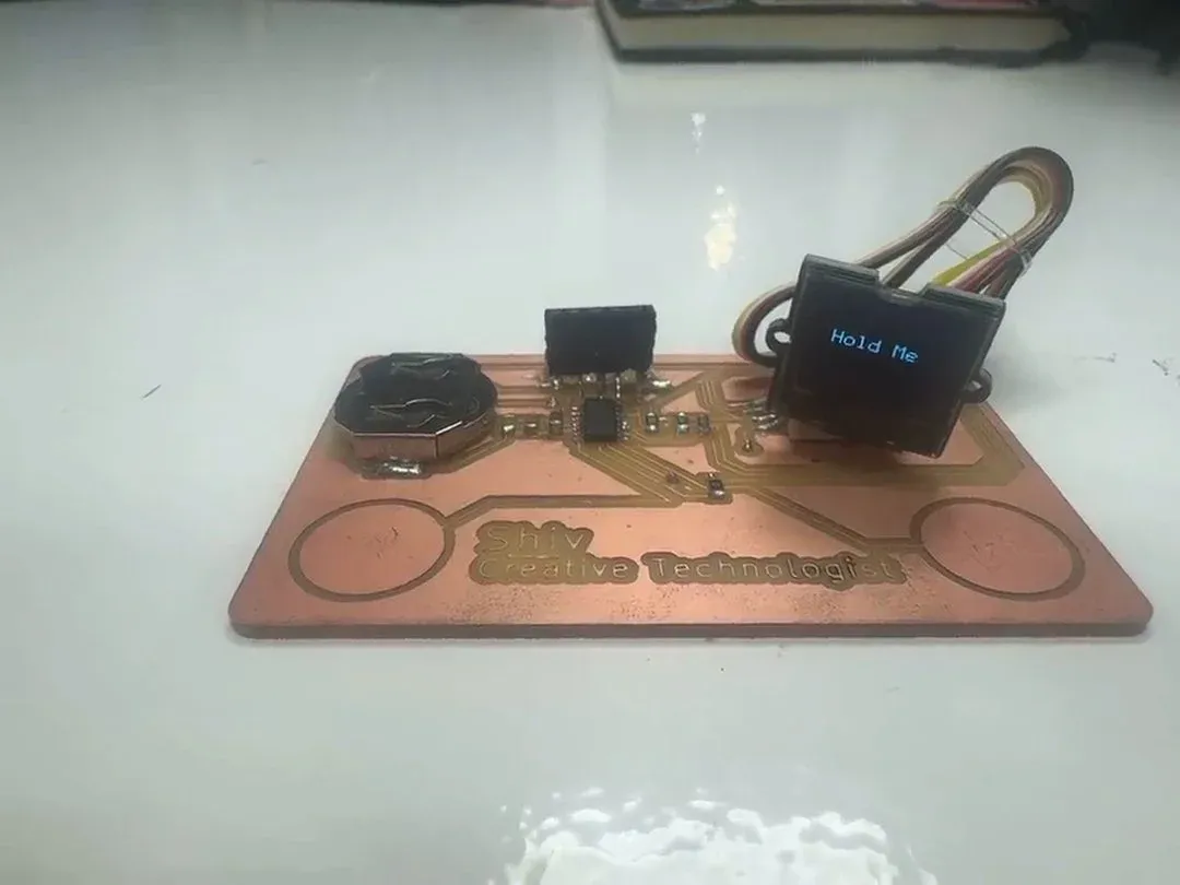
This week's assignment: add an output device to a board you've designed and program it to do something. The output device is a Grove 0.66" SSD1306 OLED — a 20×20mm module that plugs into the JST header already routed on my PCB business card from Week 8. When the capacitive touch pads are held, it scrolls personal facts. When released, it says: Hold Me.
Getting there took eight distinct failures — wrong bootloader offset, bad SERCOM routing, hardware I²C instability, a hidden framebuffer crop window, flash overflow, dead USB serial, and a flickering marquee. Each failure is documented here as a distinct lesson.
The touch sensing and calibration that drives this display is documented in Week 9 (Input Devices, linked in the sidebar). Group assignment work — measuring power consumption of output devices — is reflected on below and documented on the group work page, linked in the sidebar.
"Getting a 64×48 pixel window to say something true took eight separate failures. The OLED itself was the only working debugger."
Power Consumption: Group Assignment
As part of the group assignment, we measured power draw on the SSD1306 OLED under different conditions. Setup: bench power supply in series with a current meter, 3.3V supply, module connected directly (no microcontroller in the loop for this measurement).
- Display off (sleep mode): ~5–10µA — essentially nothing
- Display on, all pixels off: ~300µA — controller and I²C bus active
- Display on, full white: ~20–25mA — all OLED pixels at maximum brightness
- Typical text rendering (partial fill): ~5–8mA — realistic operating condition
What this measurement taught me is how much content drives power on an OLED. Unlike an LCD with a constant backlight, an OLED only spends energy on the pixels it lights — so "full white" pulls roughly 50× more than a blank screen, and the meter reading tracks directly with what's on the panel. At typical draw (~6mA at 3.3V ≈ 20mW), a CR2032 (220mAh nominal, realistically ~180mAh at 3V) gives approximately 30 hours of continuous display time — more than enough for the business card interaction. The marquee only runs when both pads are held; idle draw with display on but showing "Hold Me" is at the lower end of that range.
The Output Device: Grove SSD1306 0.66"
The Grove SSD1306 0.66" is a 20×20mm OLED module driven by the same SSD1306 controller used in common 128×64 displays — but the physical panel is only 64×48 pixels. That mismatch is the source of most of what went wrong below.
The Framebuffer Trap
The SSD1306 always operates a 128×64 framebuffer internally. The 64×48 panel shows only a crop of it. Drawing at (0,0) writes to memory the panel never renders.
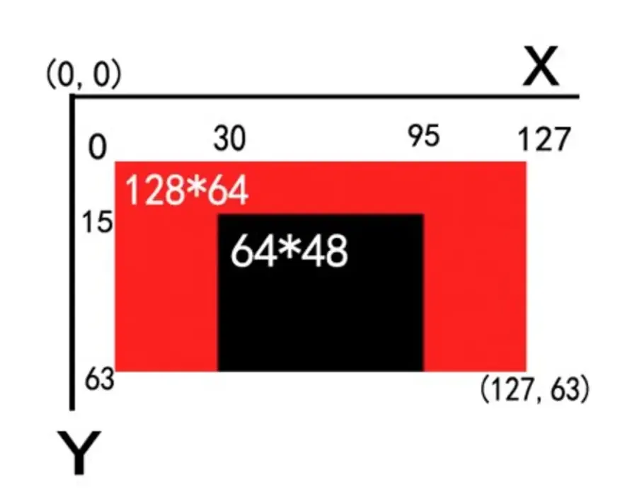
The full 128×64 framebuffer (red) vs. the 64×48 physical panel (black). Origin (0,0) is completely off-screen. Via Seeed Studio wiki.
The visible region:
X: 31 → 95   (64px wide)
Y: 16 → 63   (48px tall)
Imagine drawing on a 128×64 canvas, then placing a 64×48 window over the centre. Everything outside the window exists in memory — it just isn't shown.
Connection to the Board
The OLED plugs into a 4-pin JST header designed into the board in Week 6: VCC, GND, SDA (pin 8), SCL (pin 9). No soldering after fabrication — the header was already there.

Plug-and-play. The header was designed in KiCad during Week 6 and milled in Week 8.
Arduino Setup
Before tackling the OLED, the ATSAMD11 needed to be correctly configured in the IDE. The Fab SAM core has more settings than a standard Arduino board — most of them matter.
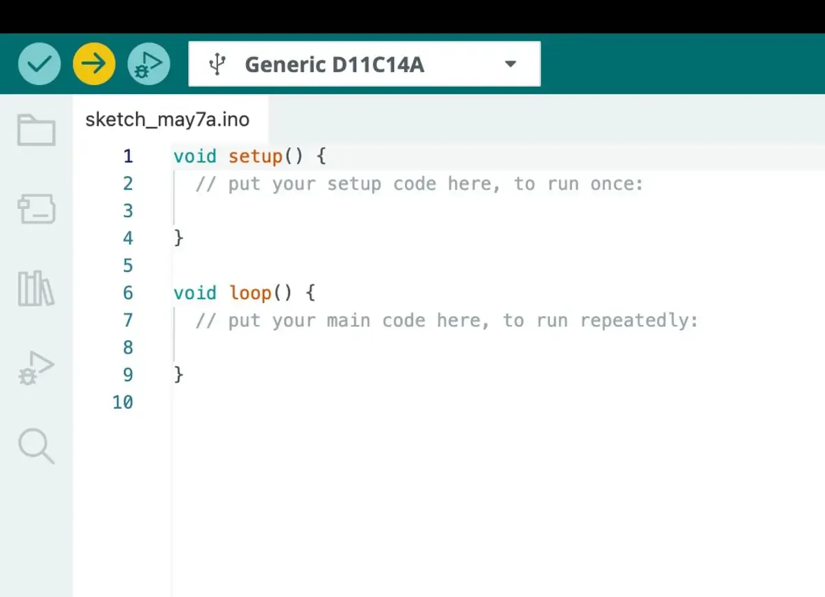
Board: Generic D11C14A under Fab SAM core for Arduino.

Programmer: CMSIS-DAP via the Quentorres SWD programmer.
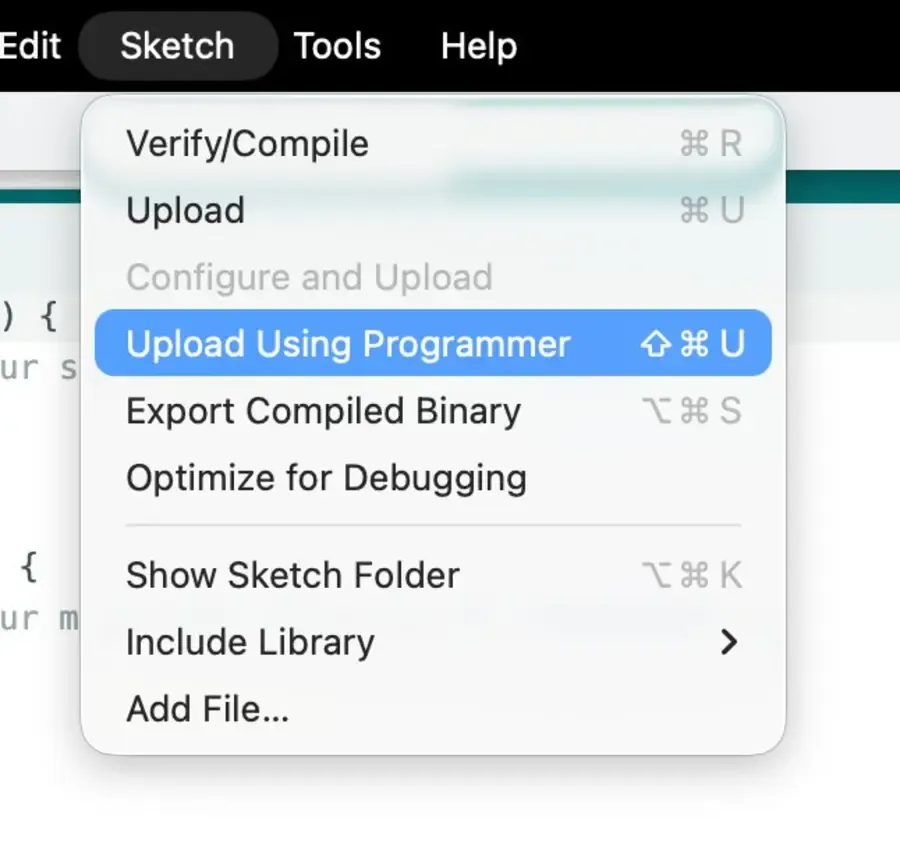
Upload Using Programmer (⇧⌘U). Not the regular Upload button, which assumes a bootloader exists.
The Debug Journey: Eight Failures
Every failure below is a distinct embedded systems lesson. They happened in roughly this order.
Failure 1 — Firmware Wasn't Running At All
Upload appeared successful. Nothing happened.
Root cause: wrong bootloader configuration. My
SWD/CMSIS-DAP workflow does direct flash writes,
but the board was set to
4KB_BOOTLOADER — which places
firmware at the wrong flash offset. The chip was
executing garbage memory.
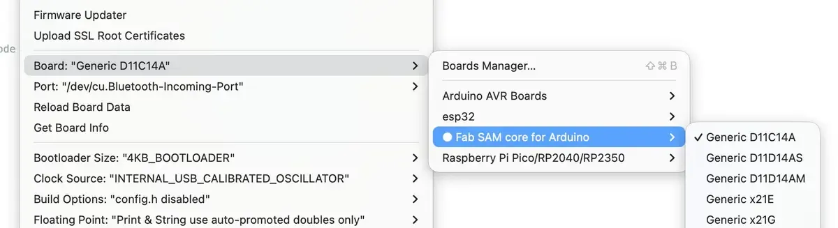
The wrong setting — firmware placed at wrong flash offset.
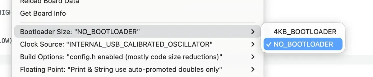
The fix. Then run Burn Bootloader — sets fuses and flash layout, not actual bootloader code.
"Burn Bootloader" with NO_BOOTLOADER is not a contradiction — it's a fuse/clock/layout operation. After this, firmware executed.
Failure 2 — No Way to Confirm Execution
No onboard LED, no USB serial. How do you prove the chip is running? Multimeter on a GPIO pad.
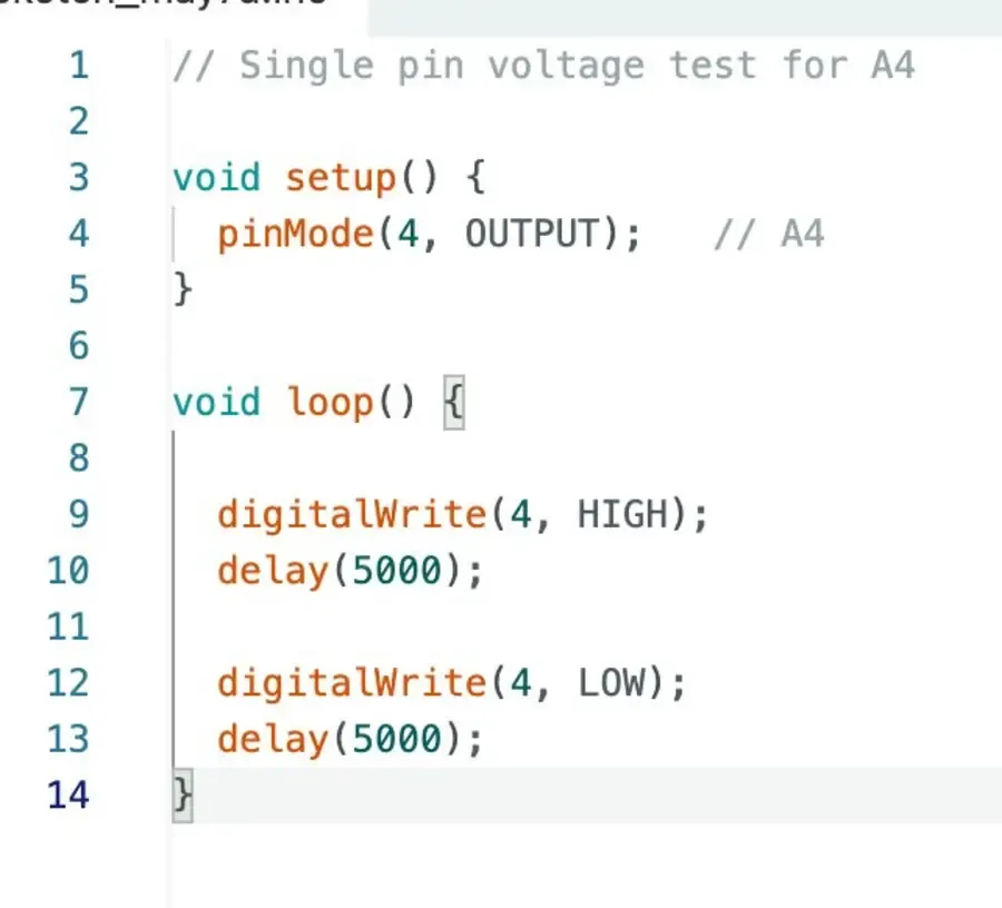
Pin A4 toggling every 5 seconds. Red probe on the pad, black on GND — watching for 3.3V ↔ 0V. No LED required.
Root Cause 1 — Wrong I²C Mapping
OLED blank. I²C scanner found nothing. My board
physically routes SDA to A8 (pin 8) and SCL to
A9 (pin 9) — but the Fab SAM core was mapping
hardware I²C to different pins under the default
Serial Config. Fix: switch to
NO_UART_ONE_WIRE_ONE_SPI.
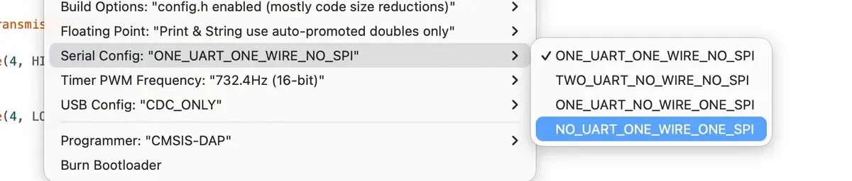
Serial Config controls SERCOM-to-peripheral assignment. This one change routes I²C to the correct physical pins. I²C scanner then found the OLED at 0x3C.
Root Cause 2 — Hardware I²C Instability
Scanner worked. OLED still blank. Hardware
Wire on ATSAMD11 with Fab SAM core
was unreliable with OLED libraries. Fix: switch
to software I²C. Bit-bangs the protocol in
firmware — slower, but completely stable on this
chip.
U8G2_SSD1306_128X64_NONAME_F_SW_I2C u8g2(
  U8G2_R0,
  /* clock=*/ 9,
  /* data=*/  8,
  /* reset=*/ U8X8_PIN_NONE
);
Root Cause 3 — Hidden Framebuffer Crop
OLED finally lit up — text appeared misaligned or invisible. This is the framebuffer crop described above. All drawing coordinates had to be offset into the visible window. Drawing at (0,0) writes to memory the panel never shows.
Root Cause 4 — Flash Overflow
The ATSAMD11 has 16KB flash. Large libraries caused:
FLASH overflowed by 668 bytes
Fixes: smaller fonts, removed
sprintf, stripped unused U8g2
features, enabled config.h code size reductions
in Build Options, removed
#include <Wire.h> (not needed
for software I²C). Every byte counted.
Failure 7 — USB Serial Never Worked
USB CDC didn't enumerate with NO_BOOTLOADER on Fab SAM core. Serial Monitor stayed blank the entire project. Fix: used the OLED itself for all debugging — printing raw sensor values and state directly to screen. Faster than USB serial anyway: real hardware, real time, no driver indirection.
Failure 8 — Marquee Flickered with U8X8
Early marquee used U8X8 (the lightweight
non-graphics variant) for speed. U8X8 is
character-grid based — it scrolls whole
character columns, not sub-pixels. Result:
chunky, flickering movement. Smooth pixel-level
scrolling requires the full U8g2 graphics mode
with
clearBuffer() +
sendBuffer() each frame.
How the Code Works
Final Working Setup
Board:          Generic D11C14A (Fab SAM core)
Programmer:     CMSIS-DAP
Bootloader:     NO_BOOTLOADER
Clock:          INTERNAL_USB_CALIBRATED_OSCILLATOR
Build Options:  config.h enabled (code size reductions)
Serial Config:  NO_UART_ONE_WIRE_ONE_SPI
Driver:         U8G2_SSD1306_128X64_NONAME_F_SW_I2C
                clock=9, data=8
The Rendering Loop
Each frame: clear buffer → draw string at current xPos → send buffer → decrement xPos. When text exits the visible window's left edge, advance to the next fact and reset.
u8g2.clearBuffer();

if (touched) {
  const char* message = facts[currentFact];
  u8g2.drawStr(xPos, 40, message); // Y=40 within visible Y:16–63

  xPos -= 14; // 14px per frame × 50fps ≈ 700px/sec

  int textWidth = strlen(message) * 6; // 6x12 font: 6px per char

  if (xPos < -textWidth + 31) { // 31 = left edge of visible window
    currentFact = (currentFact + 1) % factCount;
    xPos = 95;                   // 95 = right edge of visible window
  }
} else {
  u8g2.drawStr(40, 40, "Hold Me");
}

u8g2.sendBuffer();
delay(20); // ~50fps
The numbers 31 and 95 are the visible window edges from the framebuffer crop. Without that knowledge they look arbitrary. With it, they're the exact bounds of what the panel can show.
Final Working Output System
- Display: Grove OLED 0.66" SSD1306, 20×20mm, 64×48 physical pixels
-
Driver:
U8G2_SSD1306_128X64_NONAME_F_SW_I2C— clock=9, data=8 - Visible window: X: 31→95 · Y: 16→63
- Working features: touch-triggered UI, smooth marquee animation, 9-fact cycle, centered "Hold Me" text using crop offsets
Design Files & Source Code
The board this OLED connects to was designed in Week 6 (Electronics Design) and produced in Week 8 (Electronics Production); the touch sensing is in Week 9 (Input Devices) — all linked in the sidebar. No new board was made this week — the OLED plugs into the existing header — so the design files are the same board, linked below alongside the combined firmware.
- touch-facts.ino — full Arduino sketch (input + output combined)
- visitingcardnew.kicad_pcb — board design (KiCad), from Week 8