Overview
I built networking two ways this week. The primary work is two Barduino boards I made, talking to each other over a UART wire — one sends, one receives. Then I took the same idea wireless on Adoora, so a phone can reach the board with no wire at all.
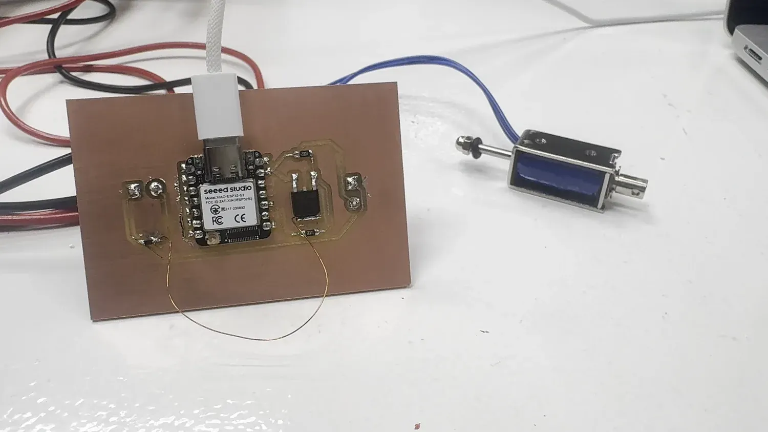
This week is the communications layer of Adoora, my sentient door lock. I designed and milled a XIAO ESP32-S3 board that drives a 12 V solenoid, and put it on the network as a WiFi access point and web server: a phone joins the board's own network and sends it an HTTP request to unlock, and the board pulls the bolt.
So there are two nodes — the phone (client) and my board (access point + server) — talking over real addresses, and the board's local output device is the solenoid. The protocols are WiFi (the board hosts its own AP) and HTTP (the unlock message).
Board to Board — Two Barduinos over UART
Before the phone ever talked to the board, the first network I built was two boards talking to each other: two Barduino ESP32-S3s I'd made, wired directly over UART (asynchronous serial) and passing a message across the gap. One board is the sender, the other the receiver, and the wire between them is the whole network.
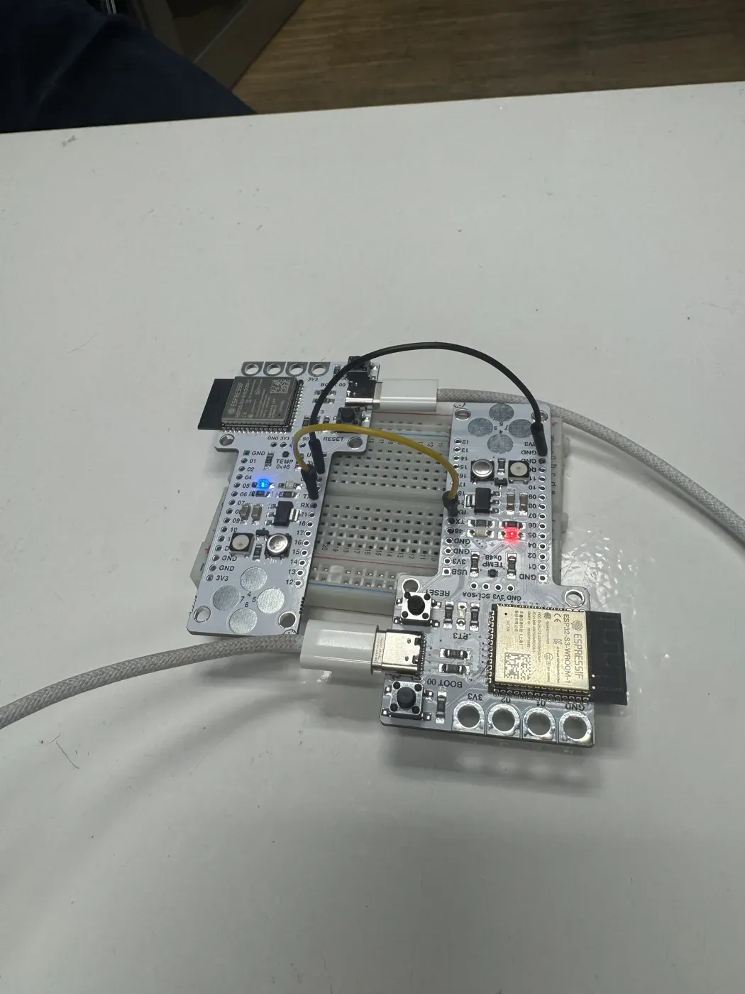
The two Barduinos I built, linked over UART — one wire carries the signal (sender's TX → receiver's RX), the other ties their grounds together.
How the two nodes are “addressed”
UART has no SSID and no IP — so what stands in for an address here is the physical wiring plus a shared frame format. The two boards only find each other if both halves of that contract line up:
-
The pins are the wiring address.
The sender's TX pin (
GPIO43) goes to the receiver's RX pin (GPIO44), and both boards share a common ground so they agree on what a 0 and a 1 even look like. -
The frame is the protocol address.
Serial1.begin(9600, SERIAL_8N1, 44,
                                    43)
sets the contract — 9600 baud, 8 data bits, no parity, 1 stop bit, on RX 44 / TX 43. If the receiver opens its UART at any other baud or frame, the same bytes arrive as garbage. That shared config is the real way the two ends “match.” - One link, one direction (here). This demo sends one way — sender transmits, receiver listens. Crossing a second wire (the other board's TX → this board's RX) makes it two-way.
The sender sketch is deliberately tiny: print to the
USB monitor so I can watch it locally, and push the
real message out Serial1 to the other
board.
void setup() {
  Serial.begin(115200);                      // USB monitor — watch locally
  Serial1.begin(9600, SERIAL_8N1, 44, 43);   // UART link: RX=44, TX=43
}

void loop() {
  Serial.println("hey");                                // to my own screen
  Serial1.println("the code transmition WORK WOHOO!");  // out the wire
  delay(250);
}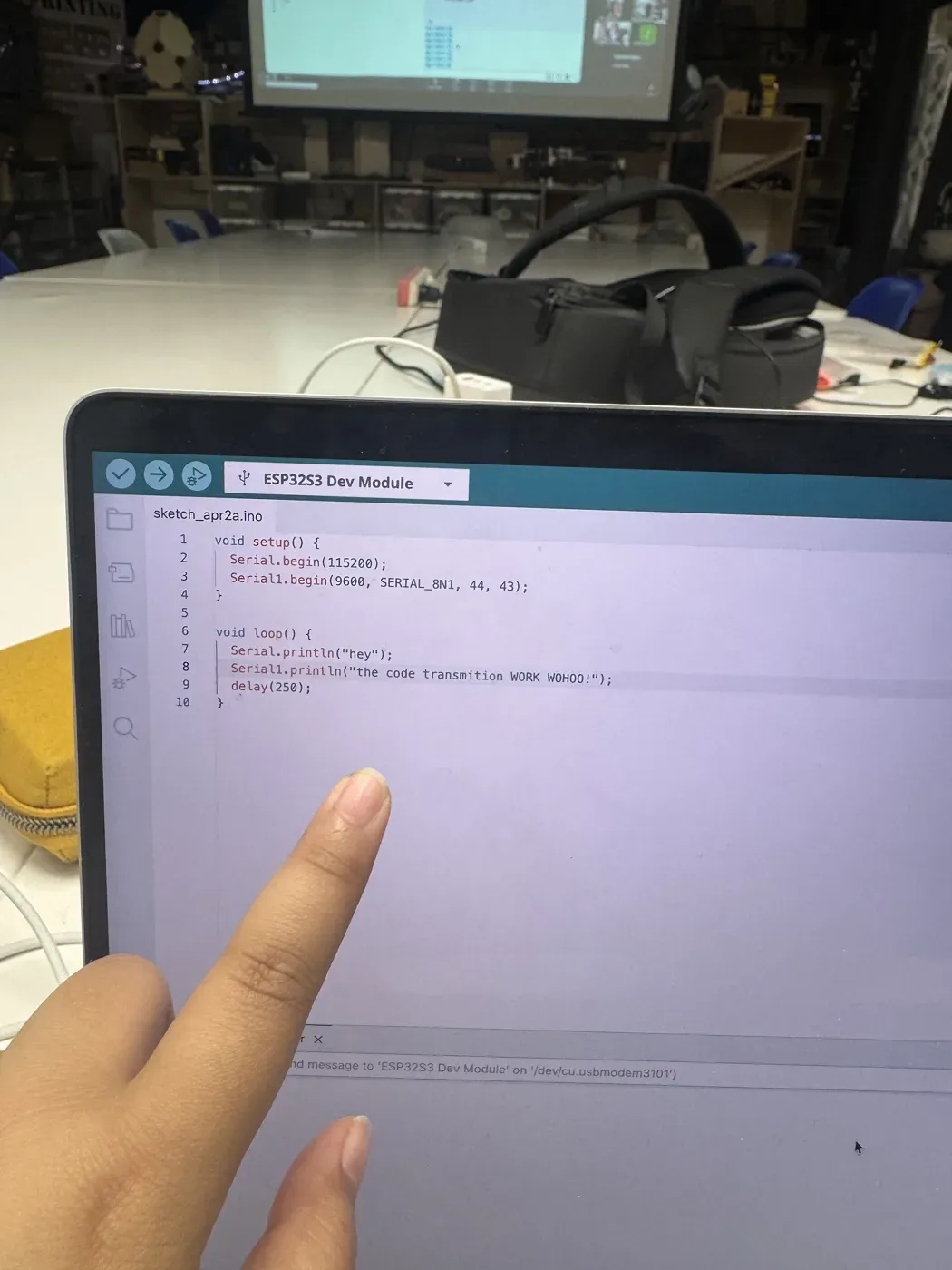
The sketch on the sender (ESP32-S3 Dev Module).
Serial1 is brought up on
RX 44 / TX 43 and the
“WOHOO” line is pushed out the wire
every 250 ms.
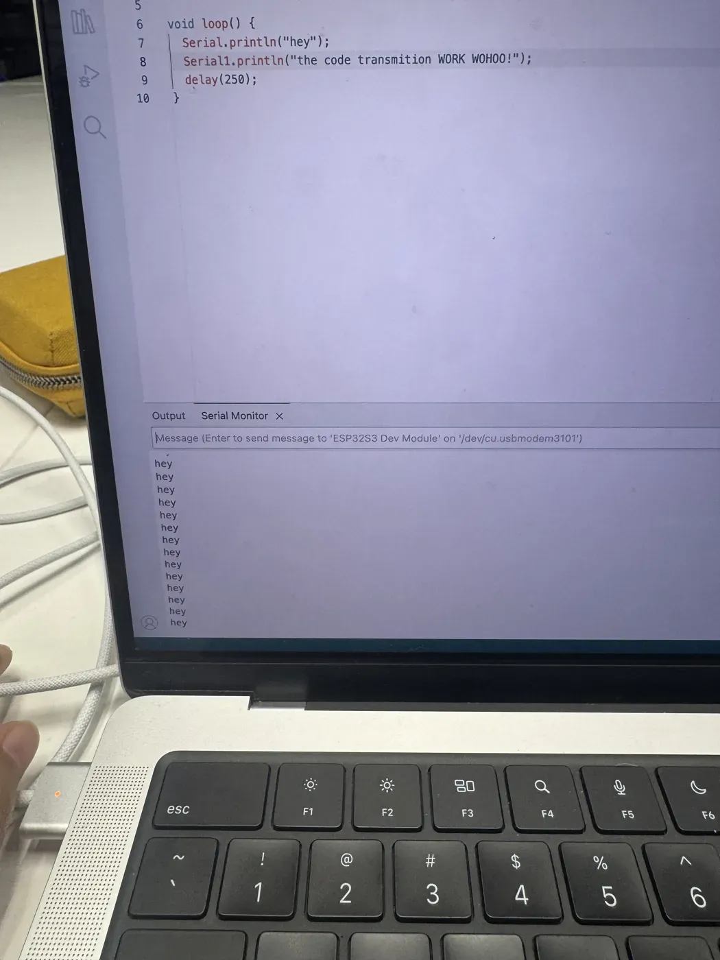
The sender's own monitor showing
hey repeating — that's the USB
Serial line, confirming the loop ticks.
The WORK WOHOO! line doesn't show here;
it goes out Serial1 to the receiver,
which prints it on its own monitor.
Two boards and one wire is already a network. Going from this to the phone-and-AP version below is the same idea with the wire swapped for radio and the pin-pair swapped for an SSID and an IP. To grow past two nodes you'd add node IDs into the message itself, or move to a bus like I²C where each device carries its own address.
The Node I Designed & Milled
The node isn't a dev board — it's a
62.25 × 27 mm PCB I drew in KiCad and
milled in copper. The XIAO's
CTRL pin (D9) runs through a 120 Ω
gate resistor to an N-channel MOSFET that switches
the solenoid; a 10 kΩ pull-down keeps the gate
low at rest, and a Schottky diode across the coil
catches the flyback spike. J1 brings in
12 V power and J2 goes out to the
solenoid.
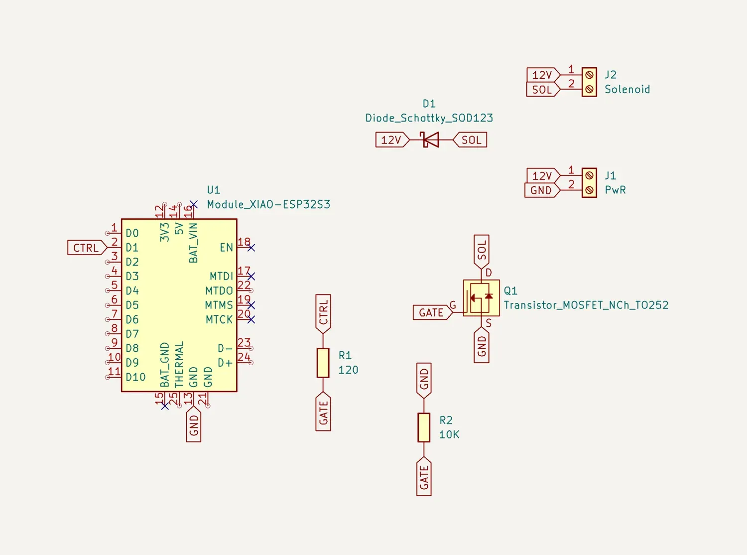
Schematic — XIAO drives the MOSFET gate (CTRL → R1 120 Ω); R2 10 kΩ pulls the gate down; the Schottky diode (D1) clamps the solenoid's flyback.
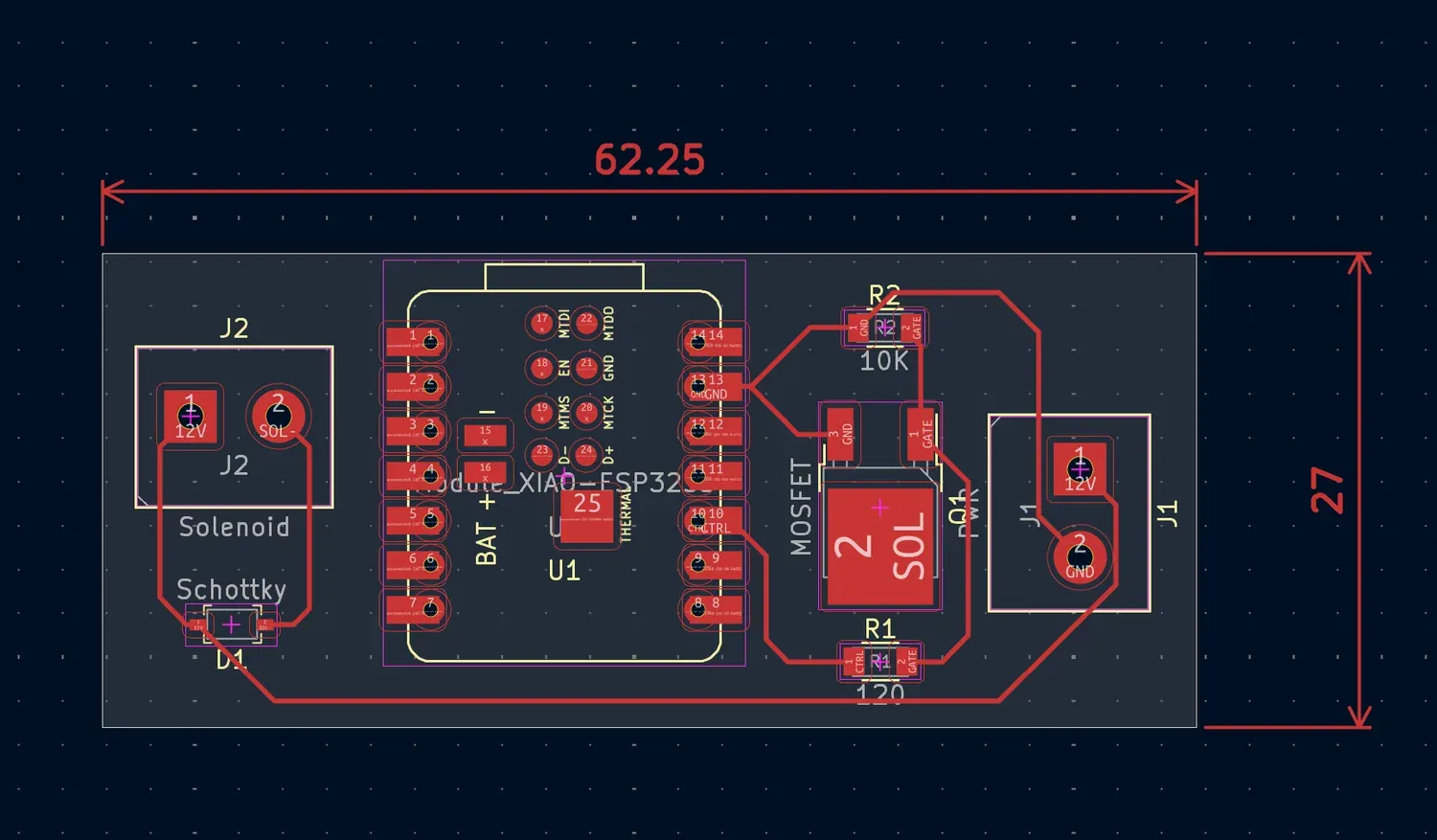
Board layout — 62.25 × 27 mm, single-sided for milling.
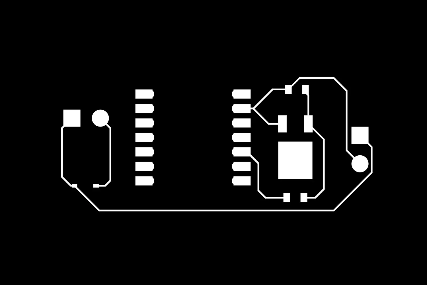
Traces and holes were exported as PNGs, then turned
into Roland mill files (.rml) — linked
below.
The Network & Addressing
The comms design has no router and no cloud — the board is meant to be its own network. The ESP32-S3 brings up its own access point and answers as a web server, so the addressing is self-contained:
-
Network identity — the board
advertises the access point
Adoora_AP; that SSID is how the phone finds and joins it. -
Address — once joined, the
board answers at its AP gateway IP
192.168.4.1; every request the phone makes is addressed there. -
Routes — the board serves a
one-page UI at
/with a Lock / Unlock button;/onunlocks (drives the pin high) and/offlocks (drives it low). -
Verification — on boot the
firmware prints
Open http://192.168.4.1to serial, confirming the gateway address it's reachable at; joiningAdoora_APfrom a phone and watching the solenoid move on a tap is the end-to-end check that the addressing works.
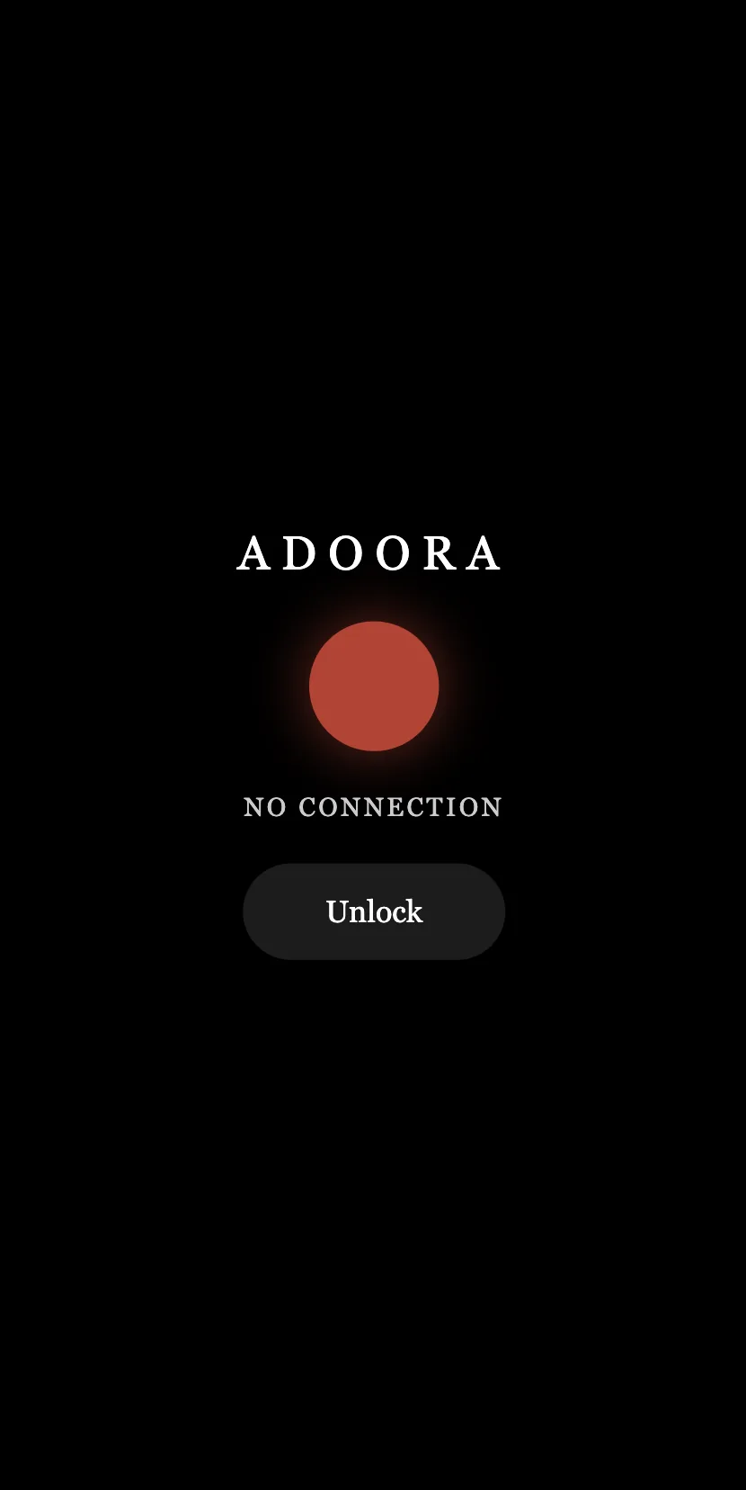
Phone not yet on
Adoora_AP — red dot, NO
CONNECTION. The page can't reach
192.168.4.1.
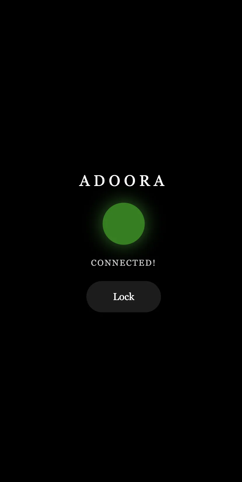
Joined to Adoora_AP — green
dot, CONNECTED. The page now reaches the
board, and the button flips to Lock.
So the network message is just a tap: a phone onAdoora_APopens the board's page and hits/onor/off, and the same pin the bring-up test toggled is now driven over WiFi.
The clip under Driving the Solenoid below
is this working end to end: a phone on
Adoora_AP tapping Unlock and Lock, and
the bolt moving on each tap.
The Programming Process — Bring-up Test
The firmware on the board is a deliberately simple
bring-up test: drive the CTRL pin (D9)
high and low once a second so the MOSFET pulses the
solenoid. It's how I confirmed the output stage —
gate resistor, MOSFET, flyback diode, 12 V rail
— actually moves the bolt before any networking sits
on top.
const int CTRL = D9;   // → R1 120Ω → MOSFET gate → solenoid

void setup() {
  pinMode(CTRL, OUTPUT);
}

void loop() {
  digitalWrite(CTRL, HIGH);  // MOSFET on  → bolt retracts
  delay(1000);
  digitalWrite(CTRL, LOW);   // MOSFET off → bolt returns
  delay(1000);
}
That bring-up test confirmed the output stage on its
own. On top of it sits the networking firmware: the
board brings up its access point, serves a Lock /
Unlock page, and drives the same pin from
/on and /off requests.
#include <WiFi.h>
#include <WebServer.h>

const int CTRL = D9;
WebServer server(80);

extern const char* PAGE;   // the styled Lock/Unlock page (below)

void handleOn()  { digitalWrite(CTRL, HIGH); server.send(200,"text/html",PAGE); }
void handleOff() { digitalWrite(CTRL, LOW);  server.send(200,"text/html",PAGE); }

void setup() {
  pinMode(CTRL, OUTPUT);
  Serial.begin(115200);
  WiFi.softAP("Adoora_AP");                 // board becomes the network
  Serial.println(WiFi.softAPIP());          // 192.168.4.1 — the address
  server.on("/",   [](){ server.send(200,"text/html",PAGE); });
  server.on("/on", handleOn);
  server.on("/off",handleOff);
  server.begin();
}

void loop() { server.handleClient(); }
The whole protocol stays standard and readable: WiFi
to join, HTTP to ask. Nothing to install — connect
to
Adoora_AP, open the address, tap a
button.
The page the board serves
PAGE is a single self-contained HTML
string — no external files, since the board has no
internet. It shows a status dot that polls the
board, and one button that flips between Unlock and
Lock. The dot is the addressing made visible: green
means the fetch to
192.168.4.1 came back, red means it
didn't.
<h1>ADOORA</h1>
<div id="dot" class="off"></div>
<p id="status">NO CONNECTION</p>
<button id="btn" onclick="toggle()">Unlock</button>

<script>
let locked = true;

// ping the board to prove we're on its network
async function ping() {
  try { await fetch('/ping'); setConnected(true); }
  catch { setConnected(false); }
}
function setConnected(ok) {
  dot.className = ok ? 'on' : 'off';
  status.textContent = ok ? 'CONNECTED!' : 'NO CONNECTION';
}

async function toggle() {
  await fetch(locked ? '/on' : '/off');   // unlock vs lock
  locked = !locked;
  btn.textContent = locked ? 'Unlock' : 'Lock';
}

setInterval(ping, 1500);
ping();
</script>
The two states above (red NO CONNECTION → green
CONNECTED!) are this script's
setConnected() running — the same code,
just before and after the phone joins
Adoora_AP. Full file:
adoora-control.html.
Driving the Solenoid
The ESP32's GPIO can't drive a 12 V, ~1.7 A solenoid directly, so the unlock signal switches the N-channel MOSFET instead: the pin raises the gate, the MOSFET lets the 12 V supply through the coil, and the Schottky flyback diode absorbs the voltage spike when the coil de-energises. Here's the message landing and the bolt moving:
The networked control working — a phone on
Adoora_AP taps Unlock and Lock at
192.168.4.1, and the solenoid retracts
and returns on each tap. The addressing working end
to end.
Problems & Fixes
1 — The ESP can't drive the coil
Wiring the solenoid to a GPIO would have cooked
the pin. Fix: an N-channel MOSFET as a low-side
switch, with the 12 V supply on its own
rail (J1) and only the gate driven
by the ESP through a 120 Ω resistor.
2 — Inductive kickback
A solenoid is a coil — switching it off throws a large reverse spike that can damage the MOSFET. Fix: a Schottky flyback diode across the coil terminals, giving that spike somewhere safe to go.
3 — Gate floating at boot
Before setup() sets the pin, the
gate could float and twitch the solenoid. Fix: a
10 kΩ pull-down on the gate so it sits
firmly off until the firmware drives it.
4 — Wrong Schottky → a burnt-out solenoid
The flyback diode was the part I learned the hard way. My first attempts used a Schottky that wasn't rated for the solenoid's flyback — too low a current / reverse-voltage rating to absorb the spike the coil throws on switch-off. After a few unlock cycles the solenoid cooked and stopped pulling. Fix: swap in a Schottky properly rated for the coil's current and reverse voltage. The takeaway for next time — spec the flyback diode to the coil before wiring anything, not after; an under-rated protection part is worse than none, because it lets you believe the circuit is safe while it slowly kills the load.
What I Learned
Making the board its own access point means the lock needs nothing else to work — no router, no app store, no second computer. The communication is just WiFi and HTTP, both of which every phone already speaks, so the “message” is a plain request to an address. The hardware lesson sat next to the network one: a message that arrives is only half of it — the board still has to switch real power safely to make something physical happen.
A network can be one board and one phone. What makes it a network is the addressing — a name to join and an address to reach — not the size.
Design Files & Source
The board is one I designed and fabricated, so its files live here with the firmware. (The Adoora app itself is documented in Week 15 →.)
- sender.ino — board-to-board UART sender sketch
- adoora.kicad_sch — schematic (KiCad source)
- adoora.kicad_pcb — board layout (KiCad source)
- adoora.kicad_pro — KiCad project file
- adoora-F_Cu.svg — front-copper artwork
- adoora-traces.rml — Roland mill file, traces
- adoora-holes.rml — Roland mill file, holes
- adoora.ino — solenoid bring-up test firmware
- adoora-control.ino — WiFi control firmware: AP + web server, /on & /off
- adoora-control.html — the Lock / Unlock page it serves