Overview
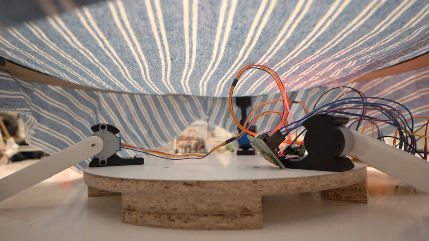
Song of the Sea is a joystick-controlled tilting platform — a laser-cut ring held up by three stepper-driven arms that meet the ring through ball-socket joints. Stretch a cloth across the ring, drop a marble on top, and steer it around by tilting the surface with a joystick. Mechanically it's a three-motor parallel manipulator — a close cousin of a Stewart platform, running on stepper motors.
This was a group project with Ramon, Tareq, and Kevin. The full machine build — mechanism, actuation, automation, the team process, problems, improvements, and design files — is documented on the group page, linked in the sidebar. This page is my individual contribution: I drove the concept & planning, the motor selection, the laser-cut ring, and the shield board. Work was spread around in pairs, so this is what I drove — not what I touched alone.
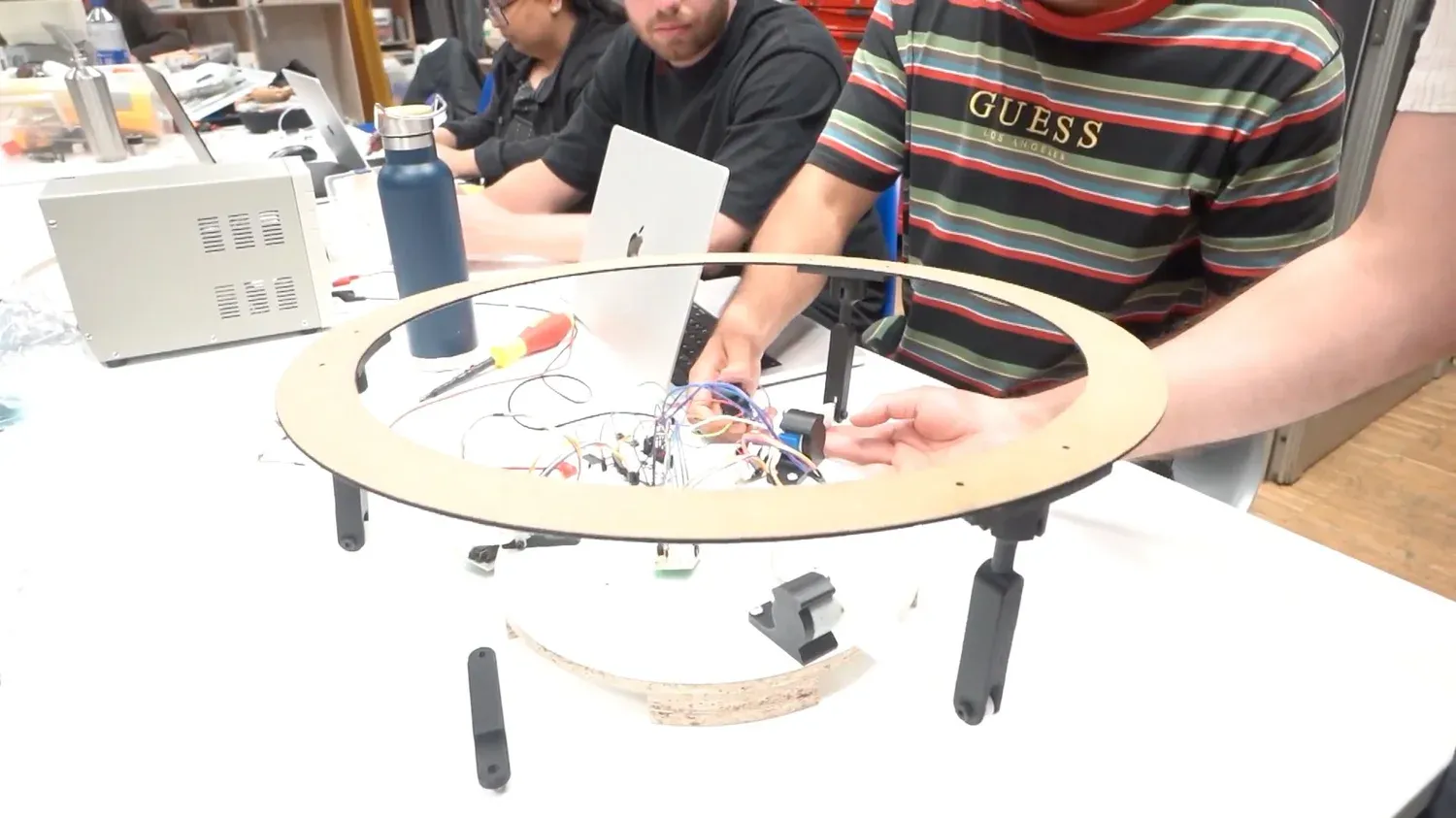
The mechanism: three arms meet the ring through ball-socket joints; lifting them by different amounts tilts the ring in any direction.
My Contribution 1 — Concept & Planning
The starting idea was a data-driven kinetic cloth: three motors mapped to the depth, speed, and heading of fish-migration tracks pulled from the GBIF and OBIS open datasets, producing a ripple through fabric — the "song" of the sea made physical. This week's brief required a machine that can be operated manually, so I proposed pivoting to a user-controlled version first: a joystick in place of the CSV data. The data-driven mode became a future extension, and almost the entire hardware stack carries over to it unchanged.
I sketched the full system by hand — three steppers, three driver boards, the central Barduino shield, the external supply, and the holder tying them together. That sketch settled two decisions the rest of the build rested on: the 120° motor layout, and treating the Barduino as the logical centre with every other part fanning out from it.
My Contribution 2 — Motor Selection
I chose the 28BYJ-48 stepper with the ULN2003 driver for four concrete reasons:
- Availability — in Fab Lab Barcelona stock, so no waiting on an order.
- Pre-paired driver — the ULN2003 ships matched to the motor and needs no trimmer or current calibration.
- Smooth resolution — 4096 steps per revolution in half-step mode, fine enough for gentle tilts.
- Shared 5V supply — runs off the same 5V rail as the Barduino.
The trade-off I had to account for: torque is modest (~300 g·cm) — enough for a light ring, but it set a hard torque budget that directly forced the ring redesign below. Picking the motor wasn't just an electronics choice; it constrained the mechanical design downstream.
My Contribution 3 — The Laser-Cut Ring
The first ring was CNC-milled plywood — structurally beautiful and far too heavy. The motors stalled immediately when they tried to lift it. This is exactly where the torque budget from the motor choice came back: the mechanism couldn't be designed in isolation from what the motors could actually move.
I redesigned the ring as a laser-cut MDF part — same outer diameter and same mounting pattern, but drastically lighter. The motors then actuated it reliably, with headroom left over for the cloth and the marble. The lesson I took from it: torque budget first, geometry second.
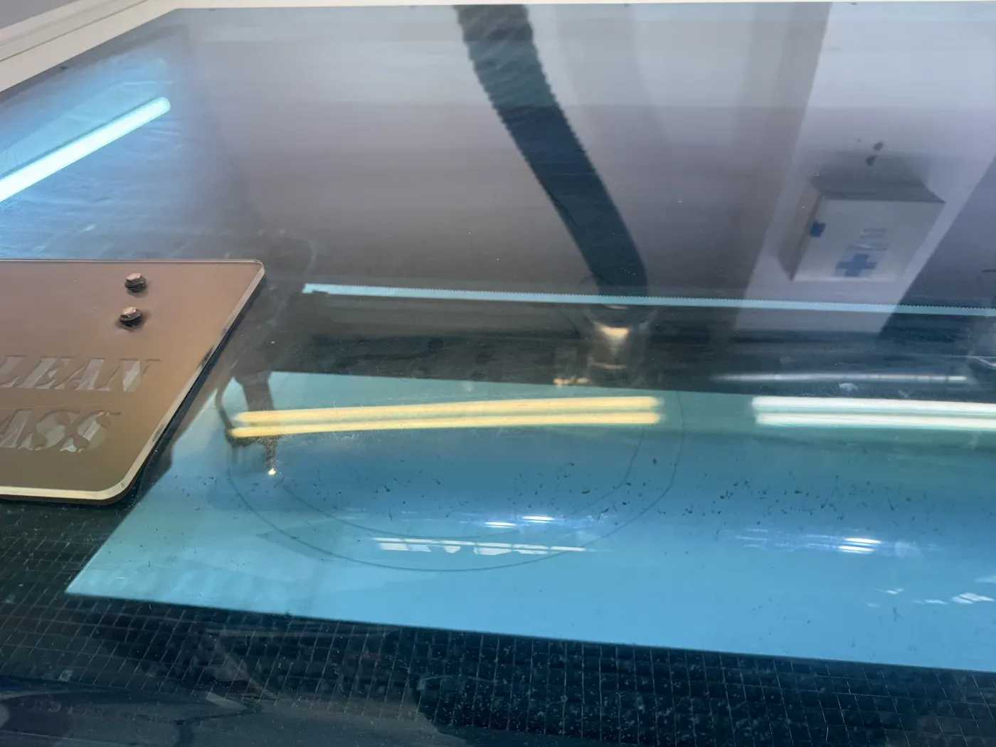
v2 on the laser bed: the lightweight MDF ring that replaced the heavy CNC one.
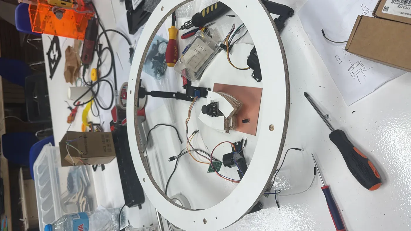
The finished ring assembled into the machine, light enough for the motors to actuate.
My Contribution 4 — The Shield Board
Rather than breadboard twelve motor GPIOs plus the joystick plus power, I designed a shield-style PCB that sits on top of the Barduino and acts as the common connection point for every wire in the machine — three driver headers, the joystick, and the shared 5V/GND rail.
The fabrication workflow:
- KiCad — schematic, then board layout
- Gerbers → gerber2img — Quentin Bolsée's tool, to convert the Gerbers into traces/outline PNGs
- Mods — toolpath generation
- Roland SRM-20 — single-sided milling
It took three milling attempts to get a usable board. The two lessons I'd carry forward: widen trace widths and clearances past the Fab Lab defaults before the first mill, and run a small test coupon first to catch endmill and toolpath issues in five minutes instead of three full attempts. (This built directly on my PCB milling experience from Week 8 — see the sidebar.)
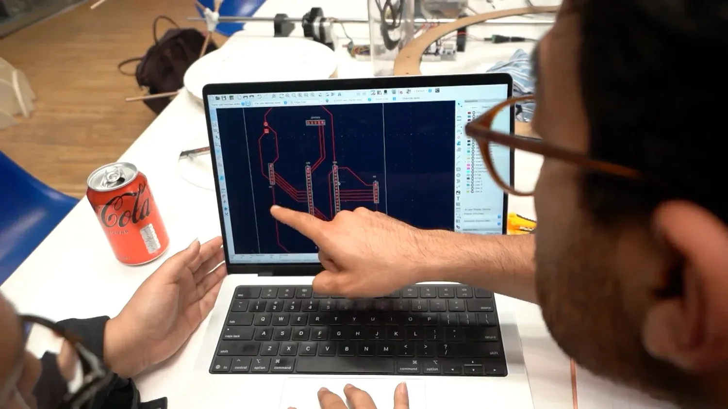
The shield laid out in KiCad — three motor headers, the joystick, and power gathered into one board.
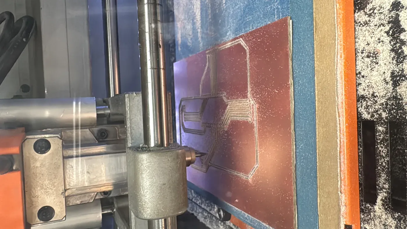
Milling the shield on the SRM-20 — the third attempt, the one that worked.
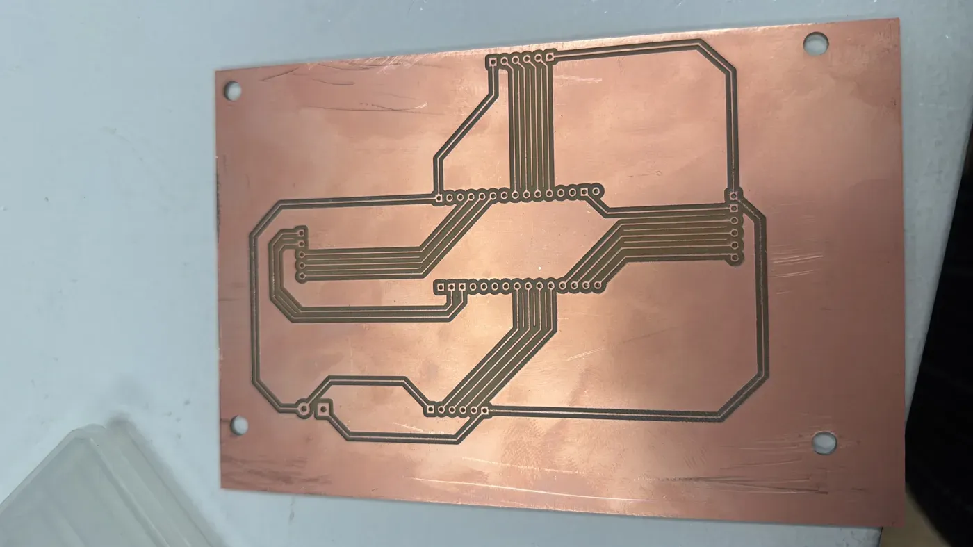
The milled shield: one board, every connection in the machine in one place.
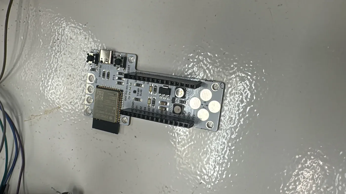
The Barduino 4.0.2 (ESP32-S3) the shield seats onto — the logical centre of the machine.
The Machine in Action
The full machine presentation — the 1-minute video (1920×1080 MP4) and the project slide (1920×1080 PNG) — lives on the group page, linked in the sidebar. Below are a couple of shots from operating it.
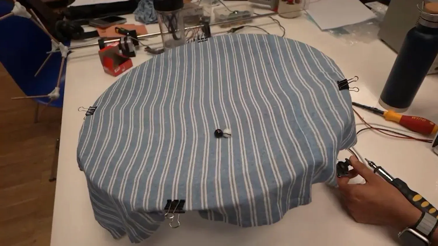
Cloth clipped evenly around the ring — binder clips at even spacing gave the tension the marble needs to roll cleanly instead of sagging.
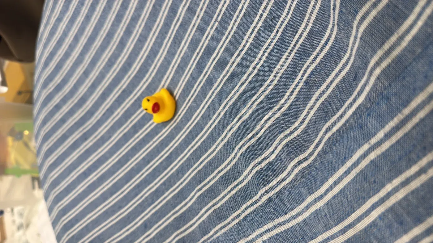
The cloth is the sea: a marble (here, a rubber duck) rides the surface and rolls toward whichever way the ring tilts.
Reflection
What stuck with me from this week is how tightly the disciplines coupled. My motor choice set a torque budget; that budget killed the heavy CNC ring and drove the laser-cut redesign; the shield board then had to gather all of that into one clean point of control. None of those four pieces was really separate — a decision in one rippled straight into the next. Working in pairs across the team, the hardest part wasn't any single part but keeping the whole signal path — joystick to Barduino to drivers to motors to ring — coherent as four people built into it at once.
"Torque budget first, geometry second" — the line that summed up the whole week. The motor you can afford decides the shape you're allowed to build.