Overview
This week was all about computer-controlled cutting, which breaks down into two main machines: the laser cutter and the vinyl cutter. Both are CNC (Computer Numerically Controlled) machines, but unlike a typical CNC that works in X, Y, and Z, cutting only uses X and Y axes. Two key modes define how these machines work: vector (for cuts) and raster (for engraving, measured in DPI, moving horizontally across the surface).
This week I ran four experiments: a conductive copper tape circuit cut on the vinyl cutter, a group kerf test, an acrylic waffle cat head, and (yes) a laser-cut tortilla. Each one taught me something different about how materials behave under a blade or a beam.
"Material is everything. Whether it's copper tape, acrylic, or tortilla; understanding your material's behaviour determines success or failure."
Key Concepts
A Brief History of CNC
Numerical control started with punch cards, computers just made it faster and more accessible. At its core, everything runs on G-code: instructions with X, Y, and Z coordinates, with the machine interpolating between those points to create paths.
How Laser Cutting Works
Fun fact: the first laser was essentially a microwave. Lasers (Light Amplification by Stimulated Emission of Radiation) used in digital fabrication are typically CO2 lasers. The system fires a focused laser beam through a nozzle onto the material surface. A smoke extraction system removes toxic fumes and a compressed air supply keeps things clean, because if smoke lingers, it overburns the material. And if you ever see a flame? Stop the machine immediately.
Laser Types & Materials
- CO2: Organic materials, high versatility
- Neodymium: Thinner materials
- Fibre: Thicker materials, easier to maintain
You can work with plastic, wood, cardboard, fabric, and more, but never metals, and materials should be max 8mm thick. Materials to absolutely avoid: PVC, carbon, chrome-tanned leather, PVB, beryllium oxide, and halogens, these release toxic gases. One interesting material: Delrin: self-healing and self-lubricating, perfect for gears.
Key Principles
- Power vs. Speed: You can either increase power or reduce speed. Finding the balance is everything.
- Lens clarity: If it's not cutting, check the lens first.
- Colour codes: Pure colours only! Red = inner cuts (cut first), Black = engraving, Blue = scoring.
- Cut order: Always inner cuts before outer cuts, material can shift once pieces are freed.
- Kerf: The laser removes a width of material. Test every material!
- Nesting: Arrange cutouts efficiently to save material.
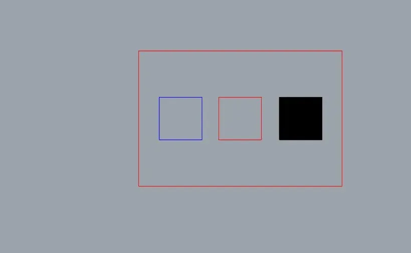
The colour code system: blue (score), red (cut), black (engrave). Must be pure colours, never mixed.
Design Techniques
- Waffle/interlocking: Fusion 360 can slice a 3D model into stackable 2D pieces
- Living hinges (kerfing): Removing strips to allow bending
- Tessellation, folding, laminating: All possible with the right material knowledge
Wood with cross-directional grain is less brittle; acrylic is beautiful but unforgiving.
The Laser Cutting Process: Start to Finish
Across all my experiments the same workflow kept repeating, so here it is as one clear process. Every laser job follows these steps; skip one and the cut fails (as my "No jobs for transmission found" error proved).
Step 0: Safety Training & Booking Test
Before operating the machines I took the lab's booking-system test, which doubles as the safety sign-off, after a tour of all four laser cutters. The non-negotiables drilled into us: only cut laser-safe materials (never PVC or certain foams; they release toxic fumes), keep ventilation, valves, and the exhaust fan running, always close the top lid before starting, run inside cuts first, and mask one side of reflective materials so the beam can't bounce off the internal mirrors. And always do a test cut first; the lab keeps test swatches for exactly this.
What the training actually changed for me was how I think about the machine. I'd quietly filed the laser cutter under "printer" load a file, press go. The safety session reframed it as something closer to an open flame on rails: the same beam that scores acrylic can set it alight, and the wrong material doesn't just fail, it releases gas that can hurt you and corrode the machine. The rule that stuck hardest was the dumbest-sounding one never walk away mid-cut because once I understood a flare-up happens in seconds, "watch the whole time" stopped being a chore and started being obvious. Booking access through a test you have to pass makes that point structural: you don't touch the machine until you've proven you know how it can go wrong.
Step 1: Prepare the File
Decide what's a cut (vector) vs. an engrave (raster). Assign pure colour codes; red for inner cuts, blue for scoring, black for engraving, and set cut lines to hairline width so the driver reads them as vectors, not rasters. Nest parts to save material.
Step 2: Load & Focus
Lay the material flat on the bed and set the nozzle height with the focusing gauge for that thickness (on the Rayjet 500 we focused with the laser height set to 0). If it isn't cutting, check focus and lens clarity first.
Step 3: Set Power, Speed & Test
Balance power vs. speed for the material, more power or less speed cuts deeper. New material with no spec sheet (hello, tortilla) means a test cut first to dial in settings, then record them.
Step 4: Cut Order & Run
Cut inner shapes before outer; material shifts once outer pieces are freed. Send to the machine driver, set the origin, and run with extraction on and the lid closed, watching the whole time.
Step 5: Weed, Account for Kerf & Assemble
Pop out the pieces. The laser removes a kerf of material, so slot fit depends on it; my "3mm" acrylic was really 3.18mm, and the kerf is exactly why the 3mm slot fit best. Factor kerf into joint clearance before trusting any fit.
As a group we toured the four lab cutters, focused the Rayjet 500 (laser height set to 0), ran test cuts from the swatch settings, and designed a Fusion tolerance comb to check joint fit; the machine specs and process notes live on the group work page.
The Vinyl Cutter
The vinyl cutter is essentially a steel blade on an X-Y axis, if you can cut it with an X-Acto knife, you can cut it on this machine. Maximum thickness: ~3mm. Not industrial-grade, but it can handle up to 10 T-shirts worth of heat-transfer vinyl.
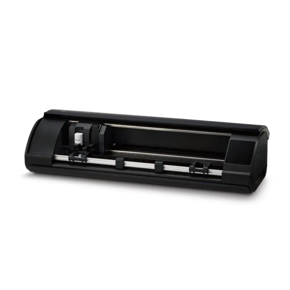
The Silhouette vinyl cutter; compact but capable
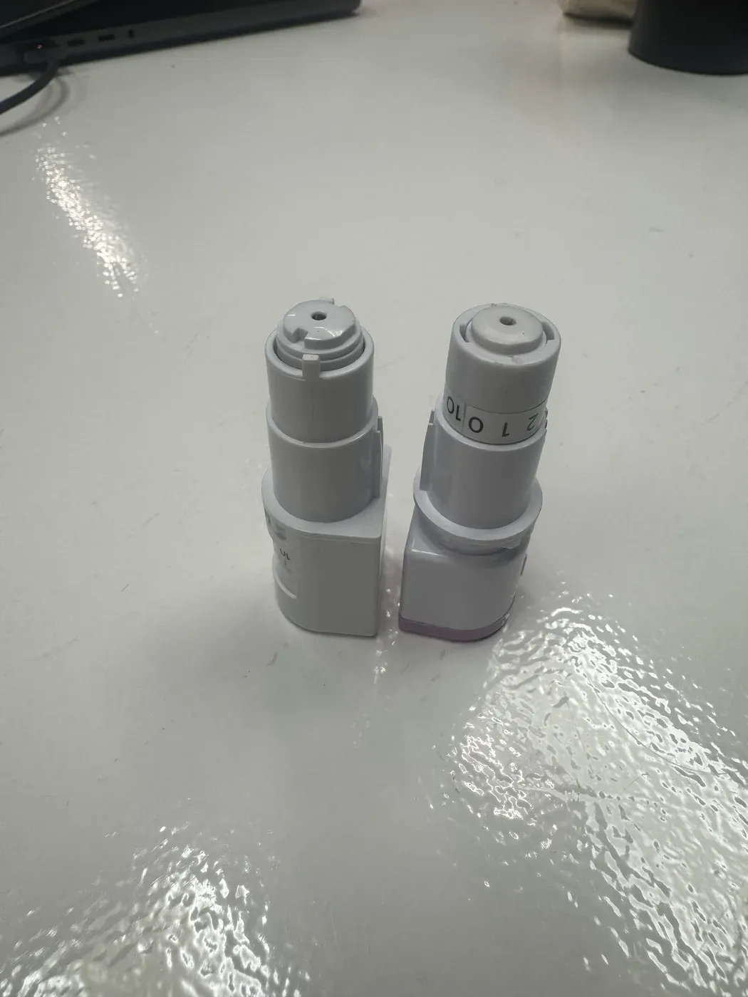
Blade holders, so tiny you could prick your finger
Important: If cutting heat-transfer vinyl (iron-on), your design must be mirrored because you're cutting the face-down side. The workflow uses Silhouette Studio via Bluetooth. For templates, templatemaker.nl is great (SVG export is paid, so convert SVG → DXF instead).
Experiment 1: Copper Tape Circuit: "The Creation of Adam"
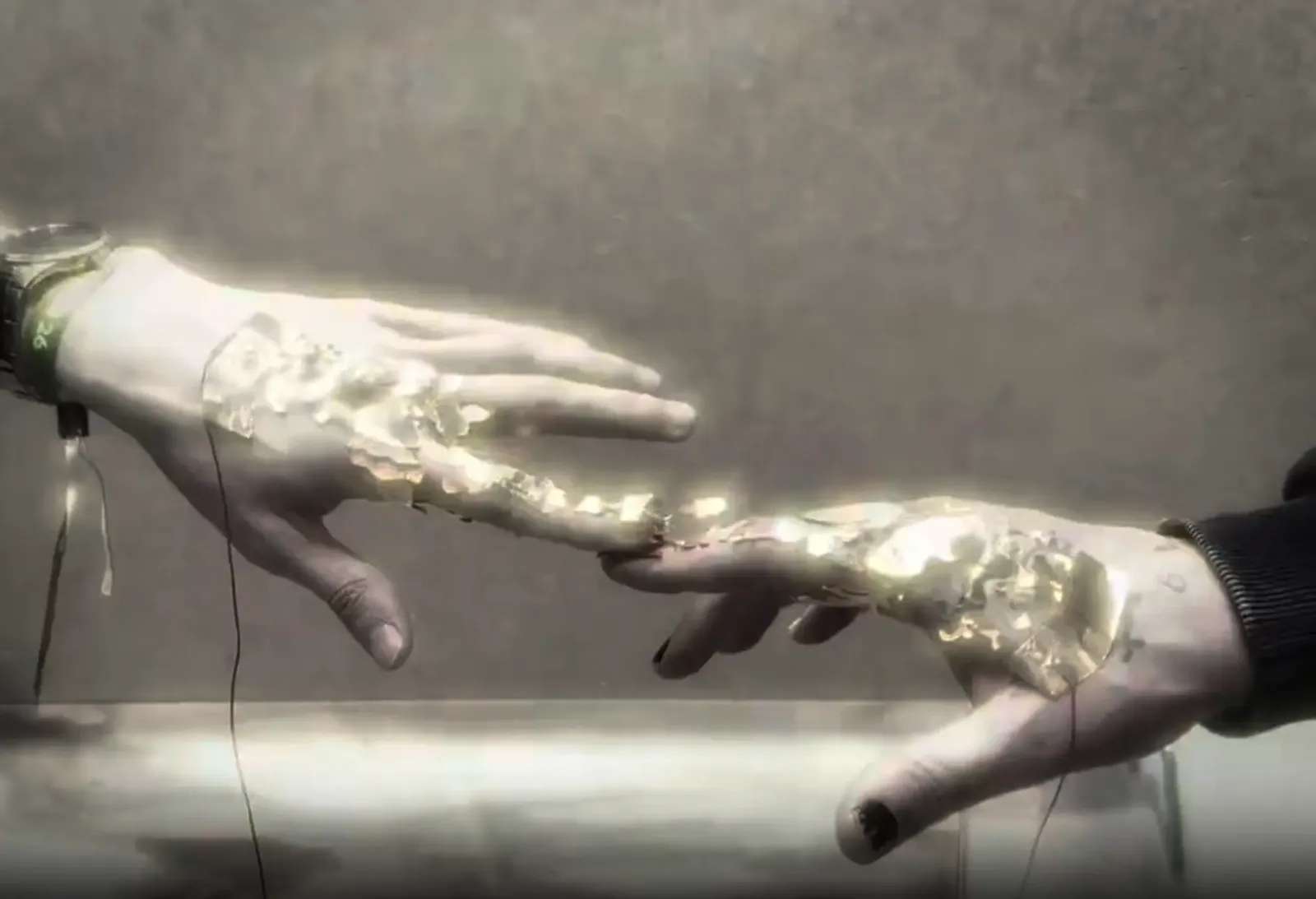
Inspired by my grandmother's intricate floral art patterns and Michelangelo's Creation of Adam, I wanted to cut a detailed design from copper tape (which is conductive) and place it on two hands. When the fingertips touch, an LED lights up; a small recreation of that divine spark moment.
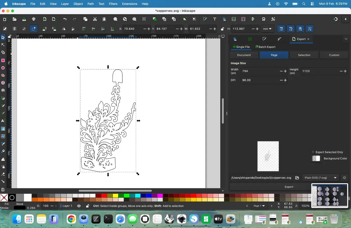
Designing the floral vector in Inkscape: inspired by my grandmother's art
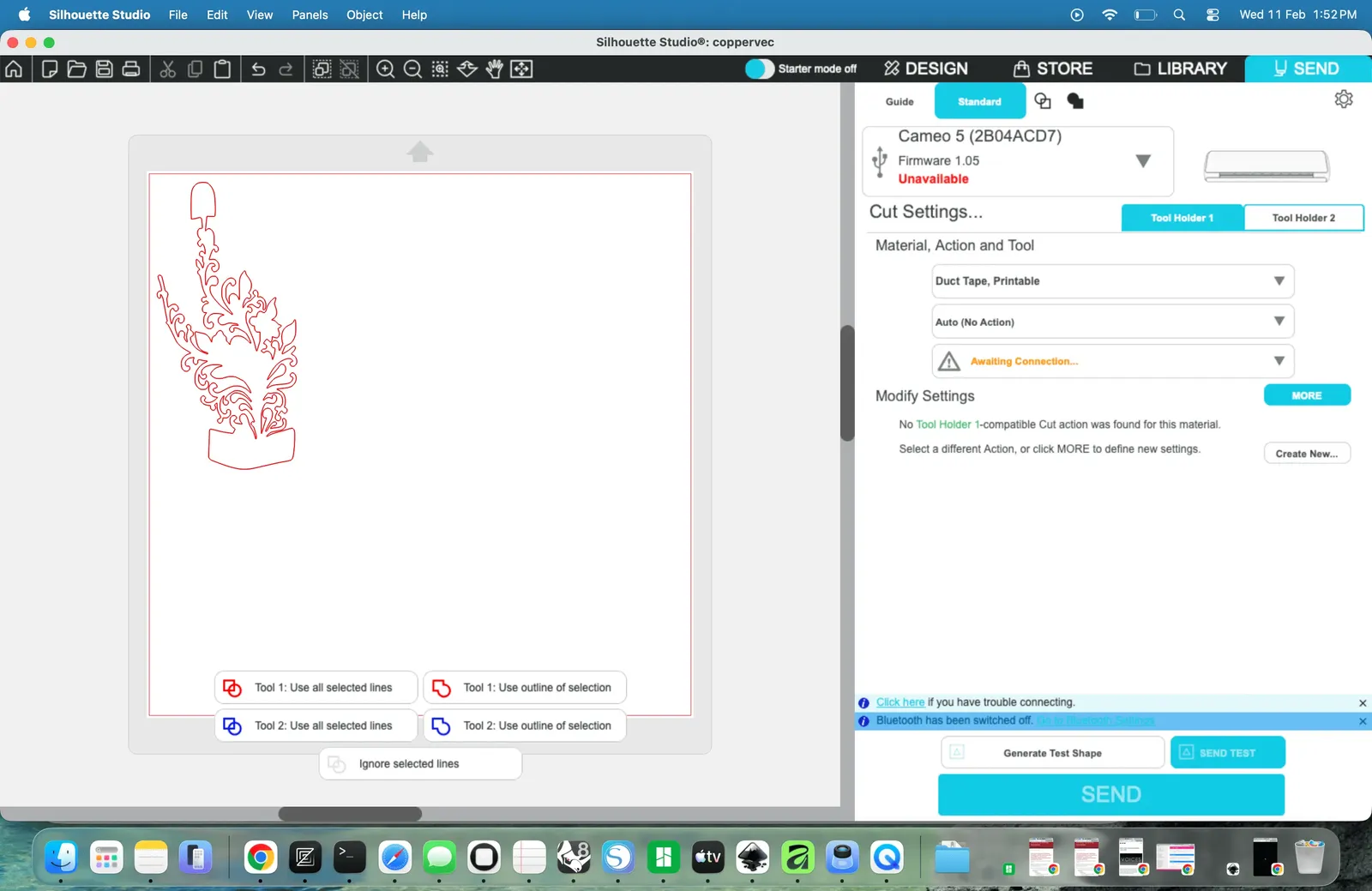
Final vector file for the cut
Challenge 1: Material Prep
Copper tape is not an easy material. It peels off, creases easily, and the blade alignment has to be perfect. I learned to squeegee the tape flat first, then cut it to the exact width needed.
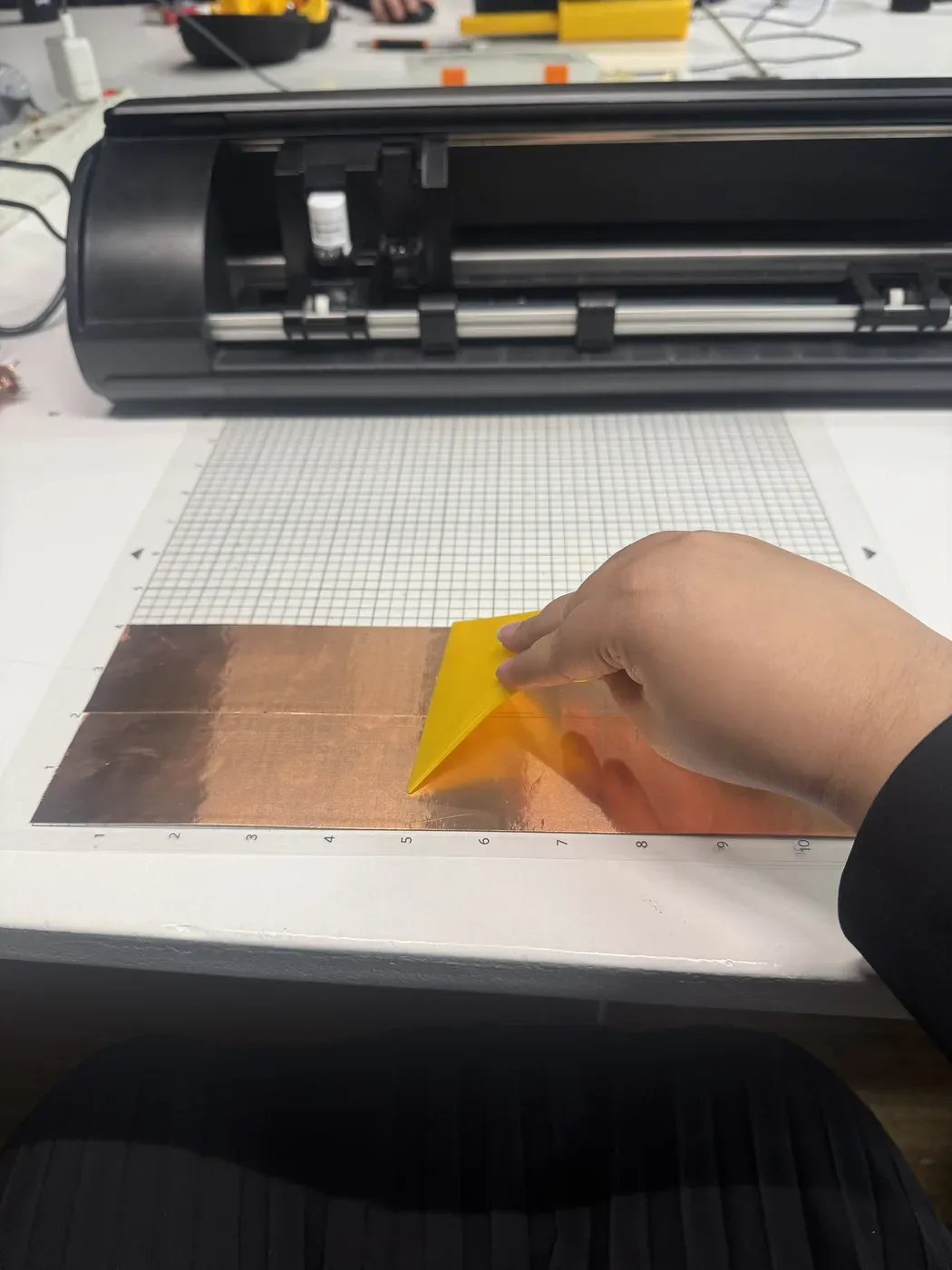
Squeegeeing copper tape flat, two strips side by side to give enough width for the intricate design
Challenge 2: Cutting Intricate Copper
My design was too detailed for a single strip, so I placed two strips of copper tape side by side to make the design larger and easier to cut.
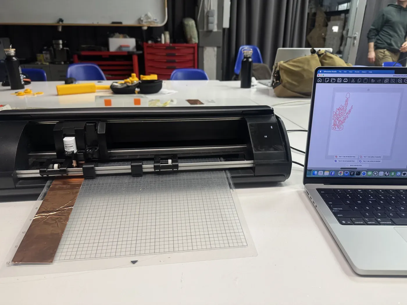
Ready to cut: copper tape on the mat, floral design loaded in Silhouette Studio
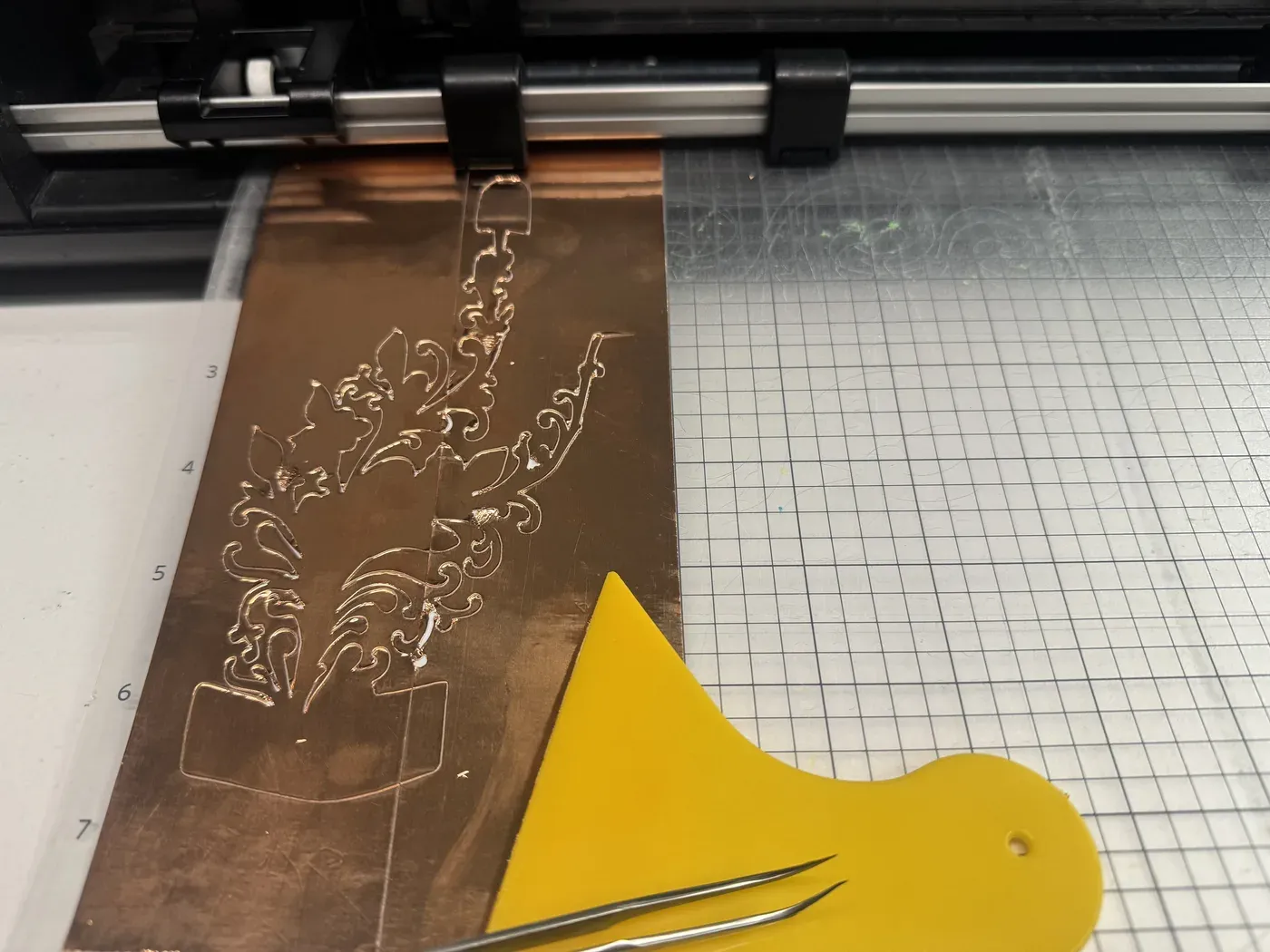
Floral design cut into copper, ready for weeding
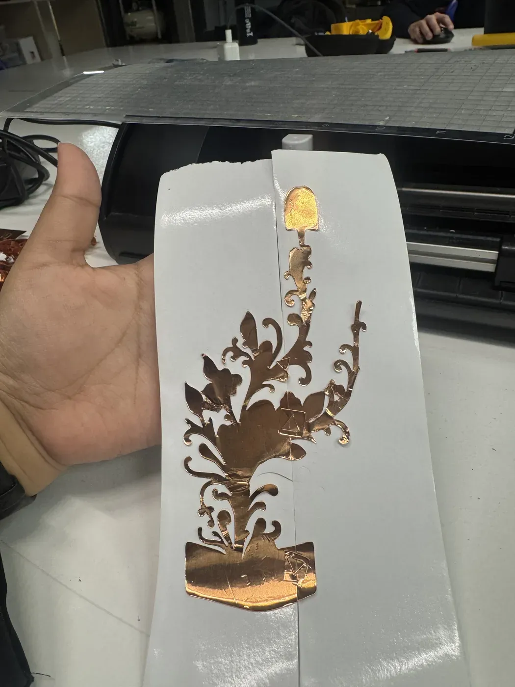
Weeded and transferred, every leaf and swirl intact
Challenge 3: Non-Conductive Adhesive
The sticky side of copper tape isn't conductive. This meant I had to fold pieces together and carefully route the wiring. Solder bridges were needed to connect the circuit across the seam.
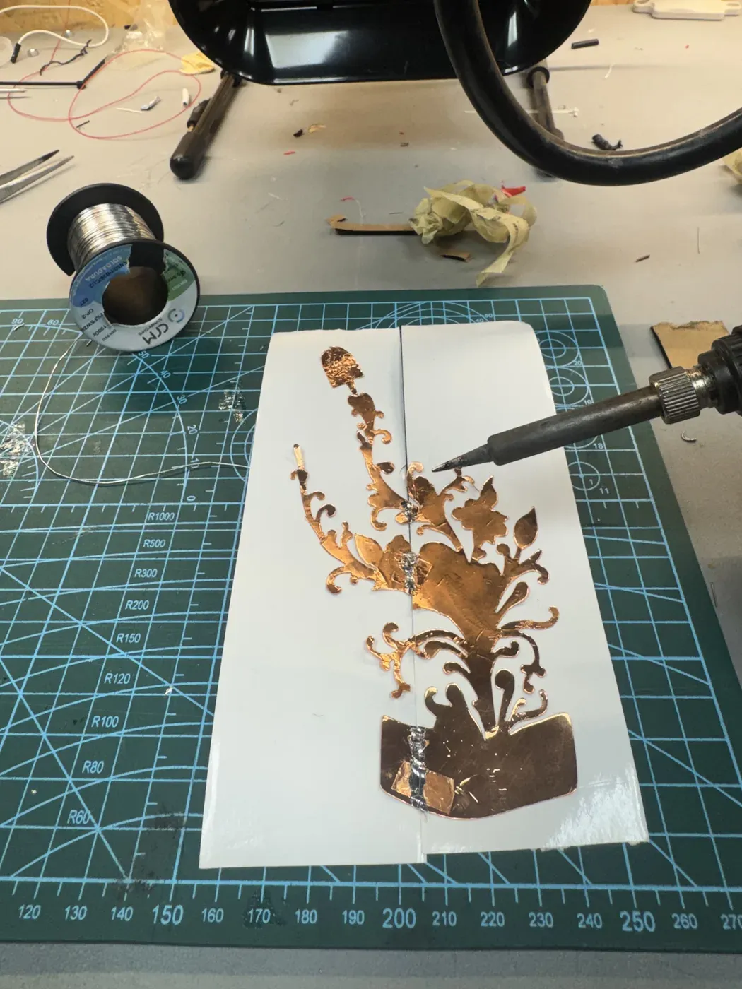
Soldering the two halves together
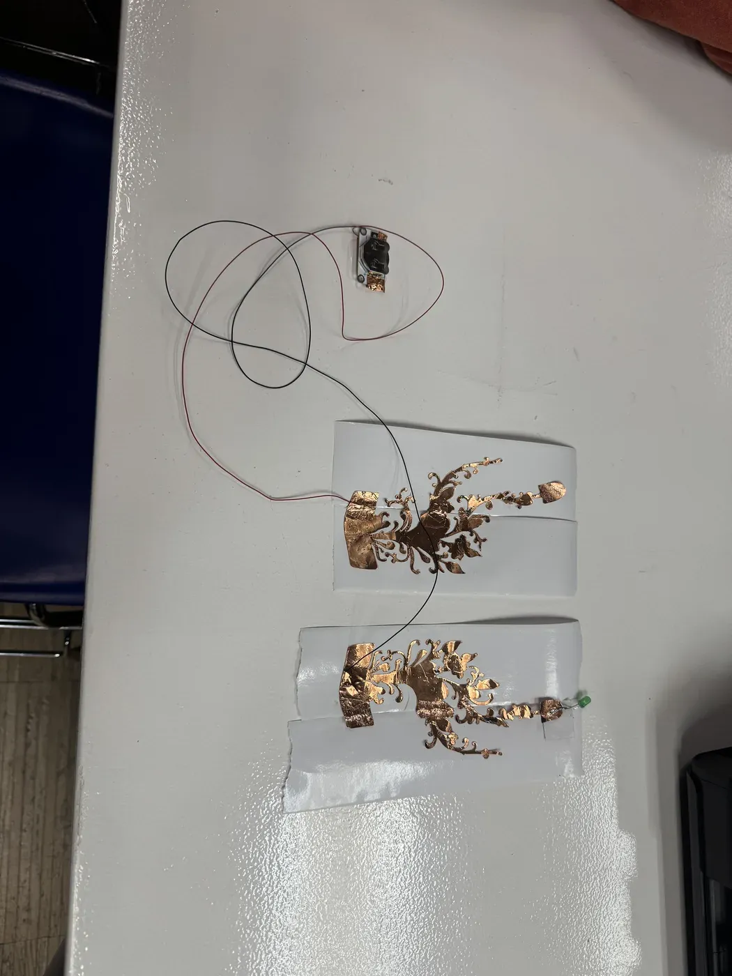
Full circuit: two floral pieces, battery pack, LED
The Moment
Once the circuit was sorted, I found a model to pose with the hands and captured the moment: the LED lighting up when two fingers touch.
The divine spark: LED lights up when the copper-tape hands connect ✨
Experiment 2: Group Project: Finding the Kerf
For our group exercise, we needed to find the kerf (the material removed by the laser) for 3mm acrylic. We created a parametric comb design in Fusion 360 , parametric meaning every dimension is defined by variables, so you can adjust the material thickness and the whole design updates.
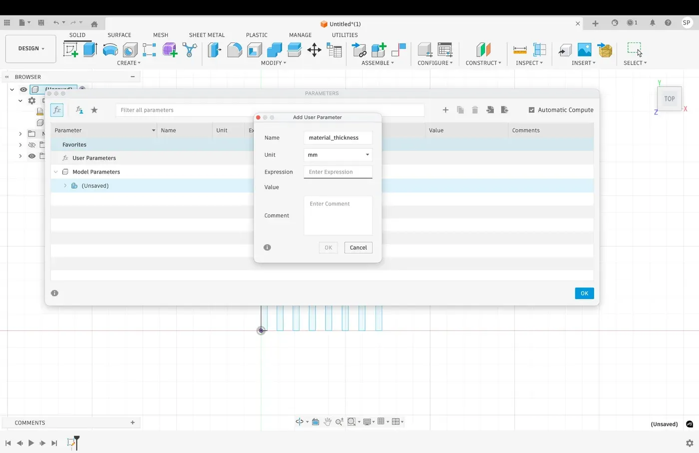
Setting up
material_thickness parameter
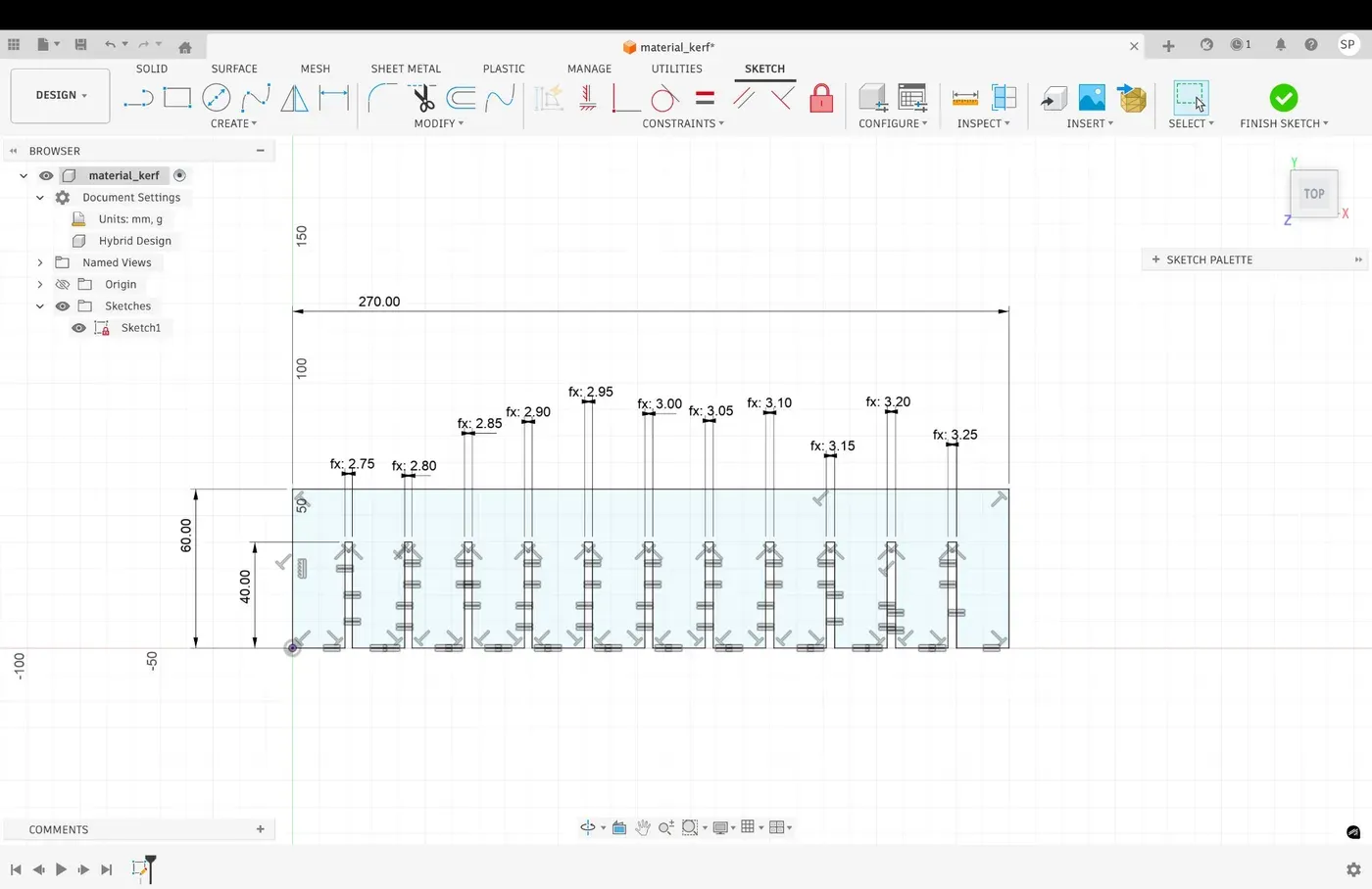
Slots from 2.75mm to 3.25mm in 0.05mm increments
The Comedy of Errors
Step one of laser cutting: find the USB.
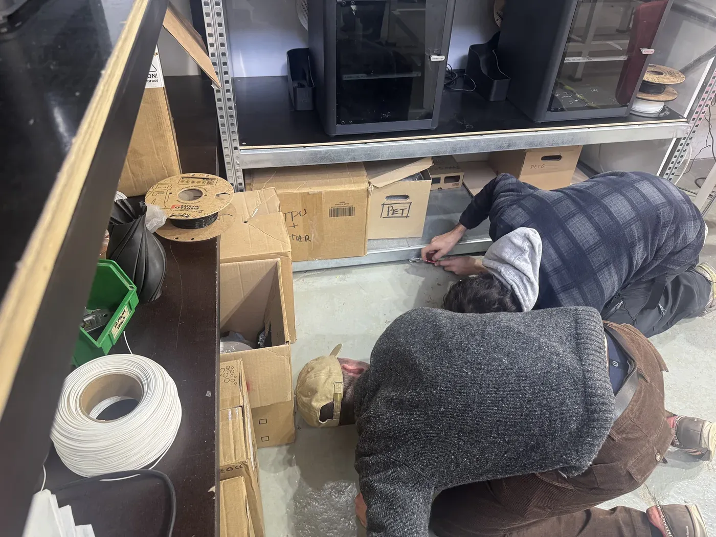
Crawling behind 3D printers. Glamorous.
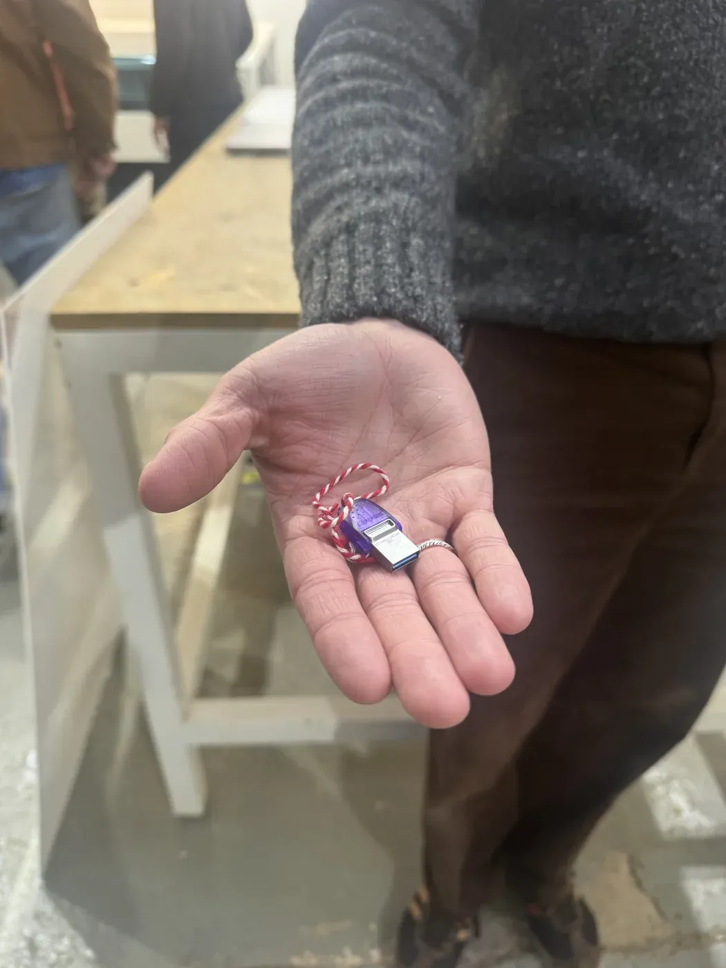
Found it! The tiny culprit with its string.
Then our first cut came out at the wrong scale, not 1:1. Once we fixed that, we could finally test the fit.
Testing & Results
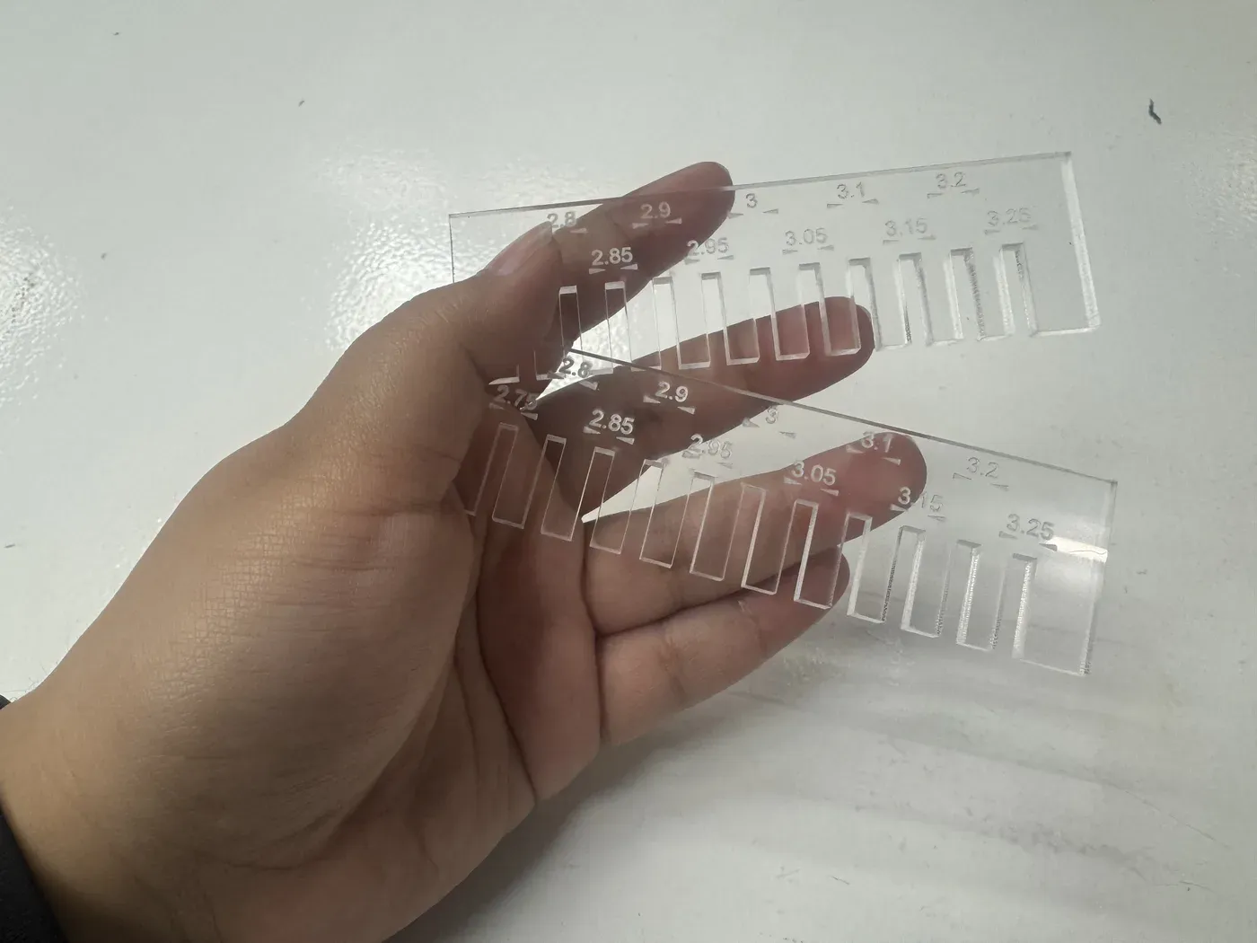
Cut combs with engraved slot widths visible
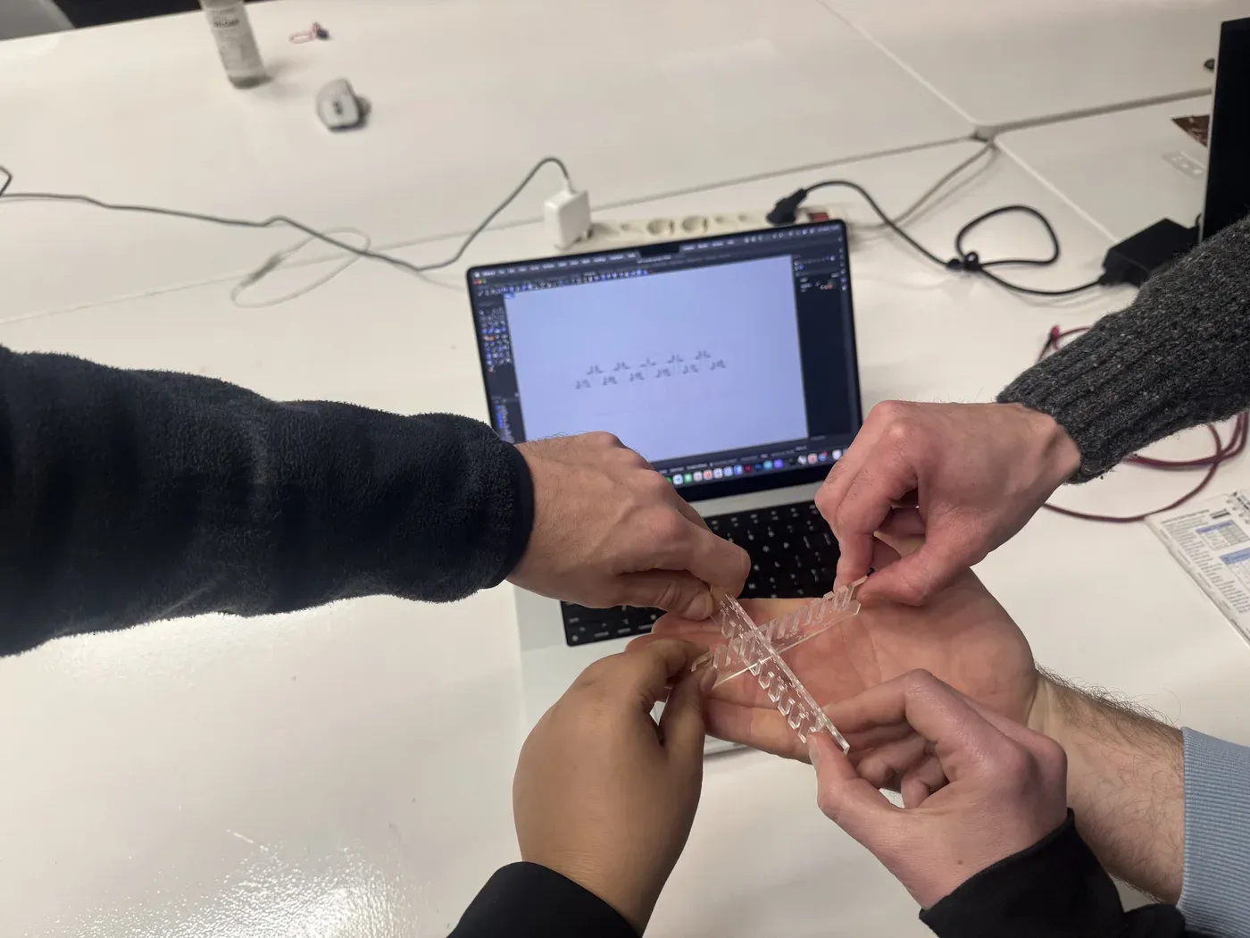
Testing the fit: multiple hands needed!
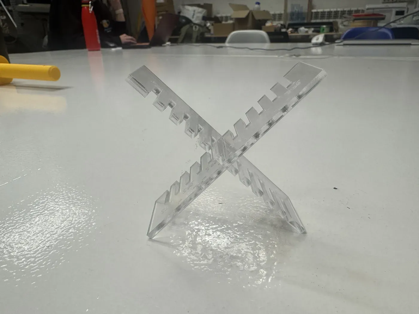
Interlocked: best fit at the 3mm slot
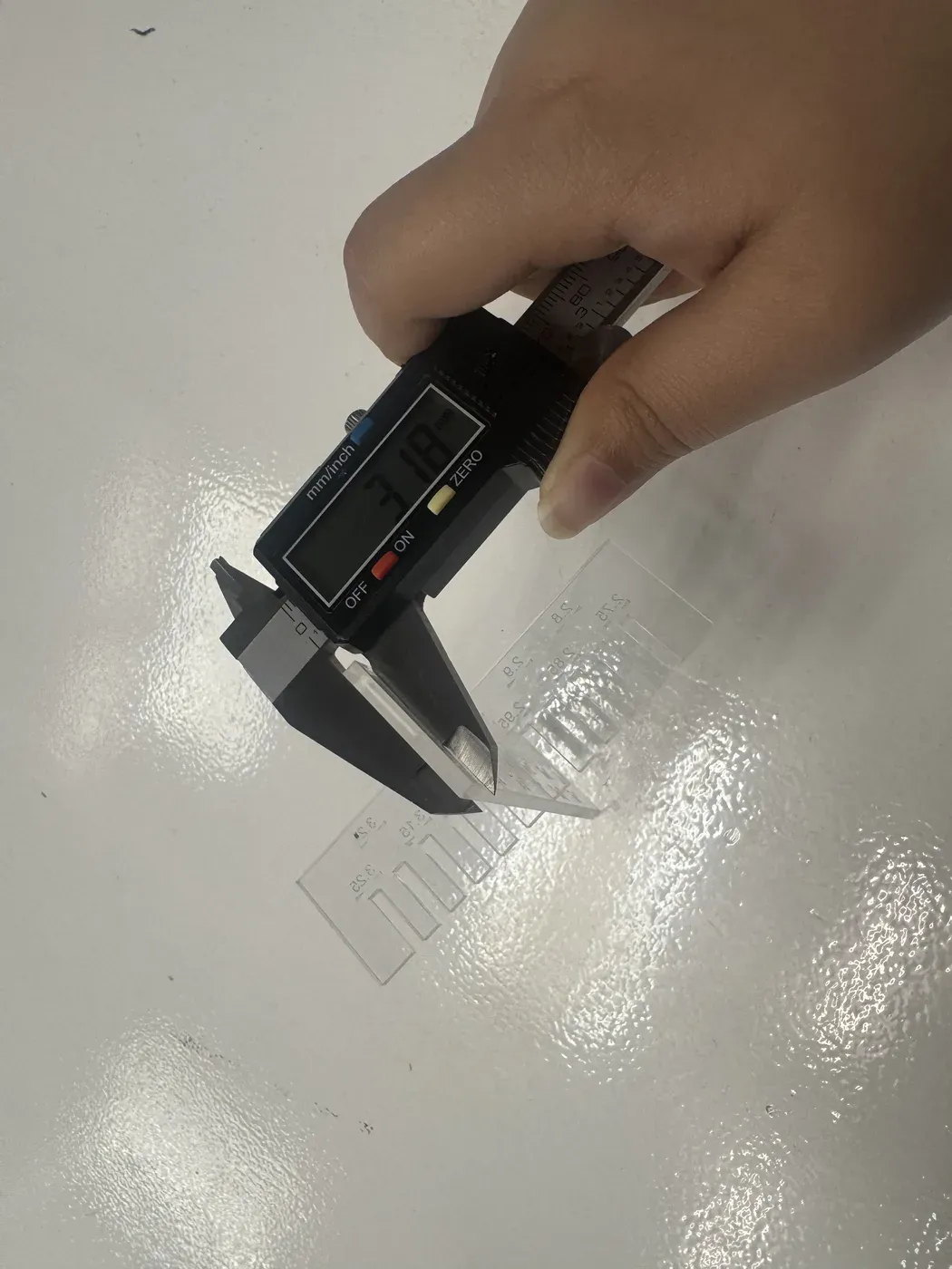
The reveal: acrylic was actually 3.18mm!
"The 3mm slot was the best fit on '3mm' acrylic because the kerf removed just enough material to compensate for the actual 3.18mm thickness."
Experiment 3: Laser-Cut Acrylic Cat Head
I used the same 3.18mm acrylic for my individual project: a waffle-structure cat head that bobbles and catches light beautifully.
Step 1: Model & Slice
Modelled the cat head as an STL in Fusion 360, then used Fusion Slicer to generate the waffle pattern, 10 slices on the first axis and 9 on the second.
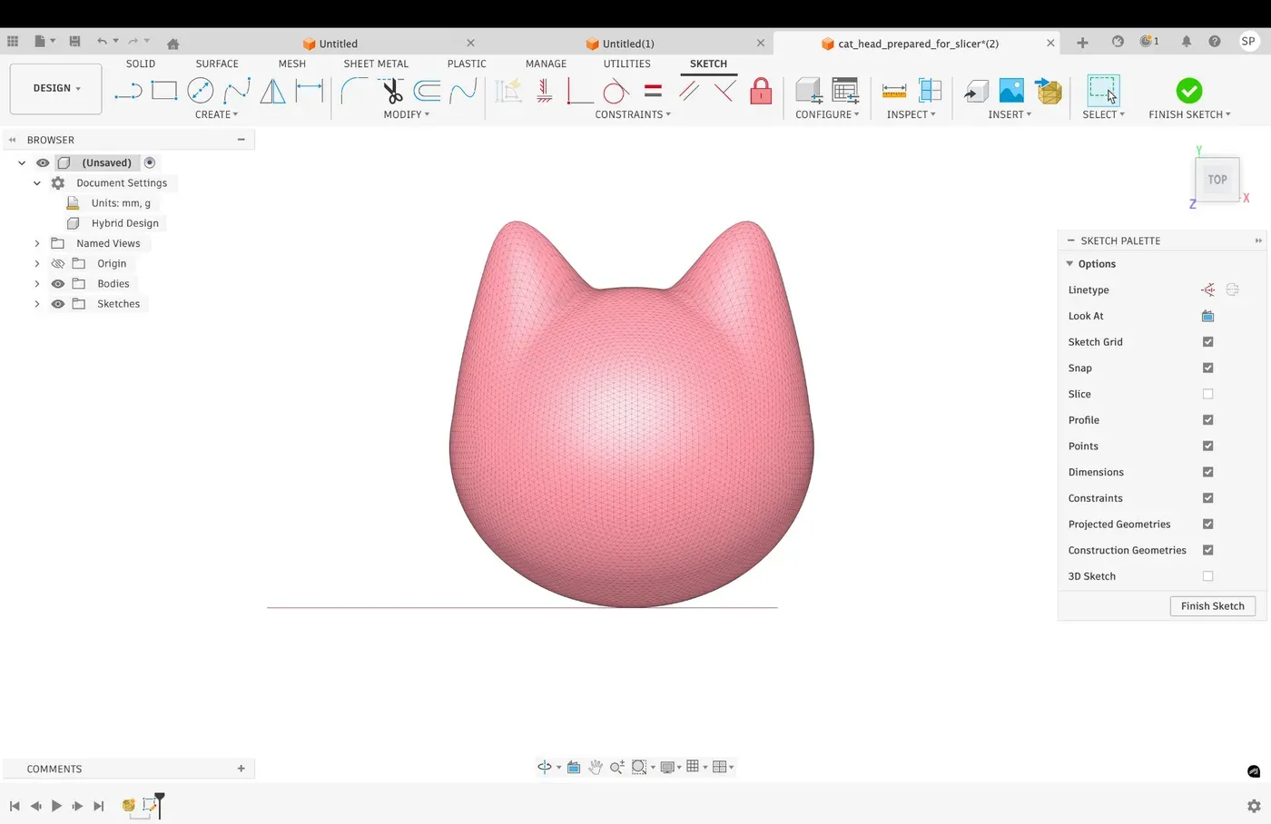
The cat head in Fusion 360: deliberately simple and abstract but immediately recognisable
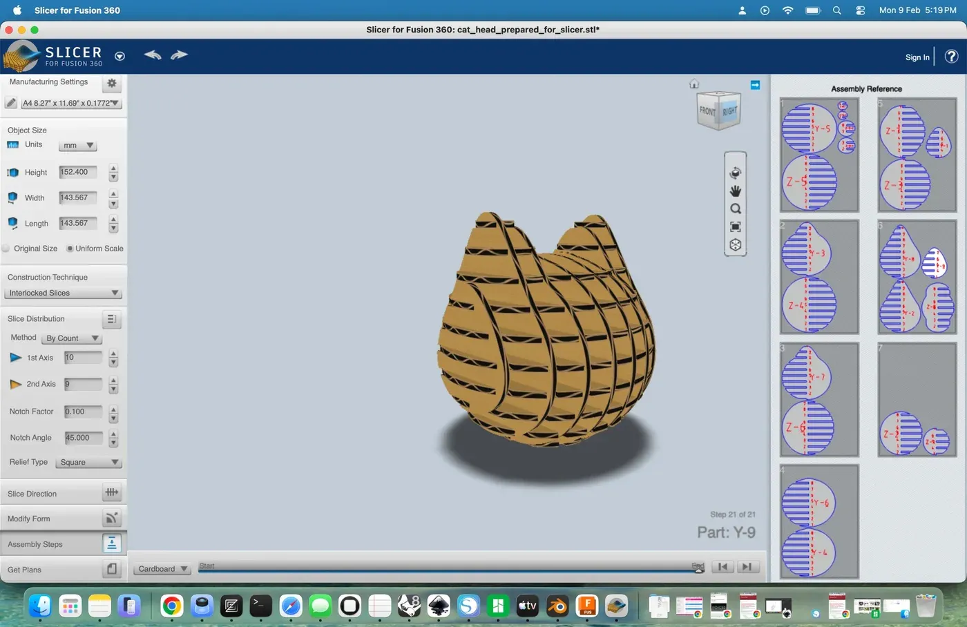
Interlocked slices preview in Fusion Slicer
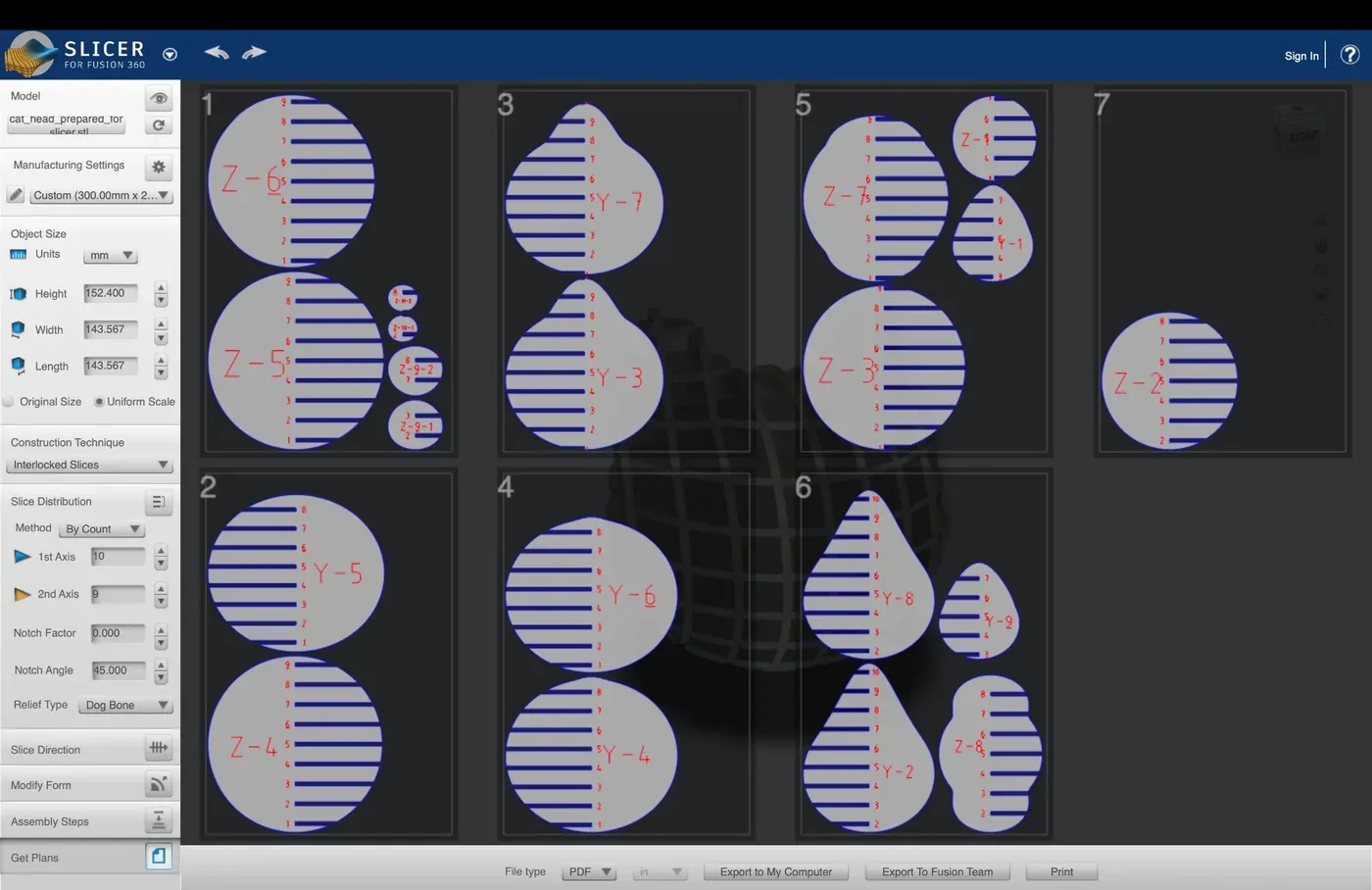
2D cut plans across 7 sheets
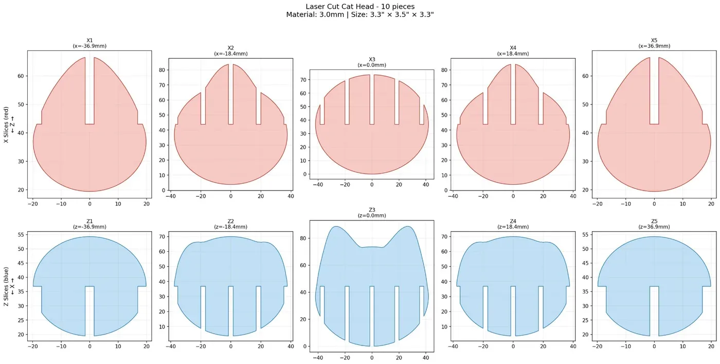
All 10 pieces: X-slices (red) and Z-slices (blue). Finished size: 3.3" × 3.5" × 3.3"
Step 2: The "Hairline" Headache
I kept getting a "No jobs for transmission found" error from RayjetManager. After much frustration, I discovered that Rhino's RayJet driver is extremely finicky about line width ; it must be set to exactly hairline. Even half a pixel wider and it treats your vector as a raster.
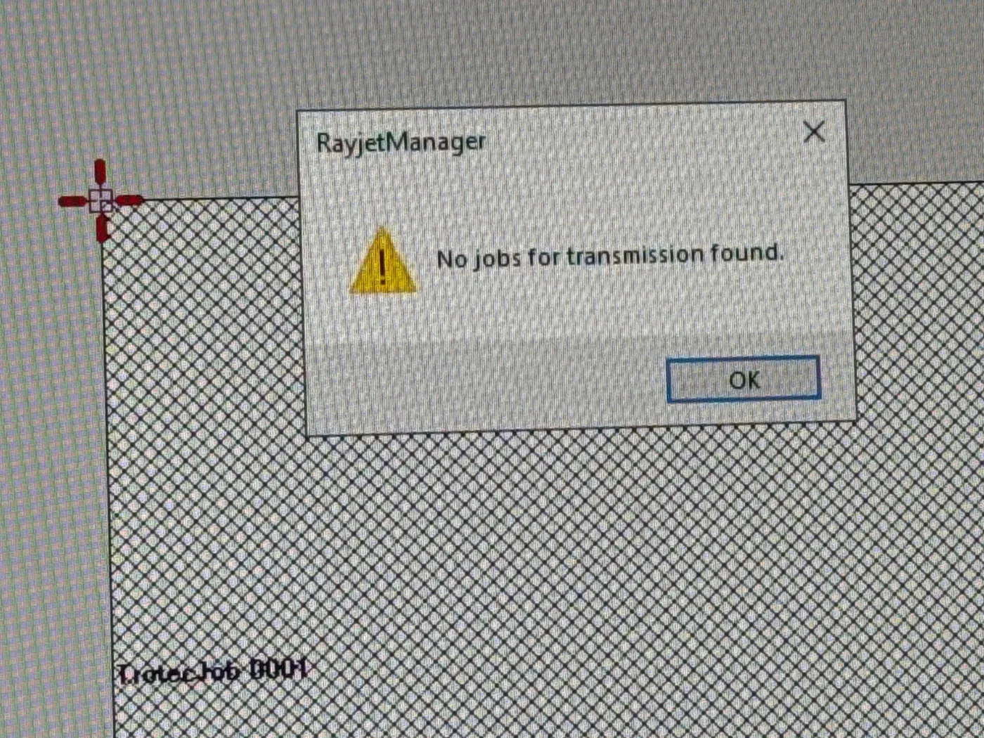
The dreaded error, one pixel too wide and the machine ignores your entire design
Step 3: Cutting
Once I fixed the hairline issue, it was time to cut. Setting the nozzle height with the focusing tool is critical for a clean cut.
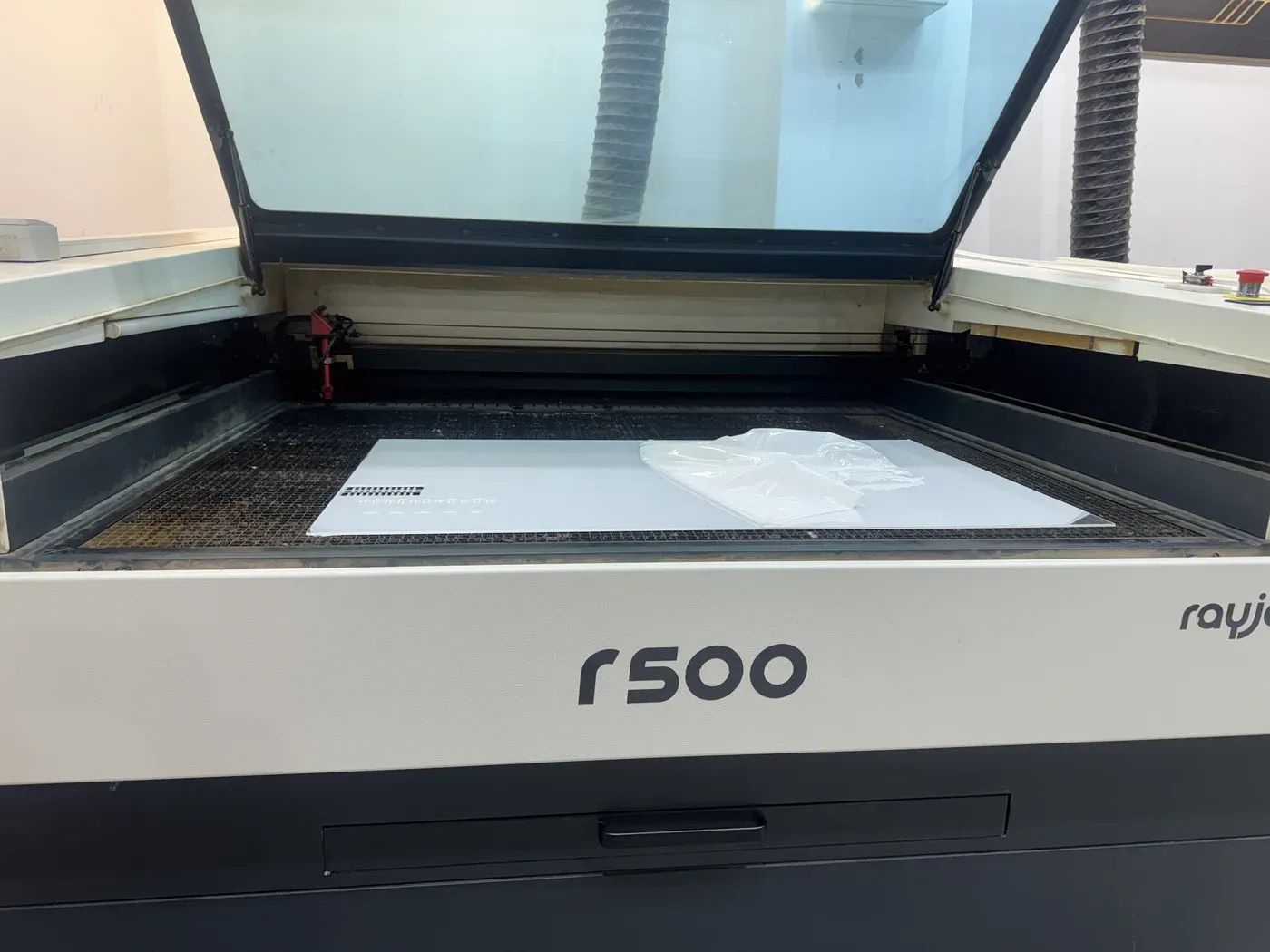
RayJet r500 loaded and ready
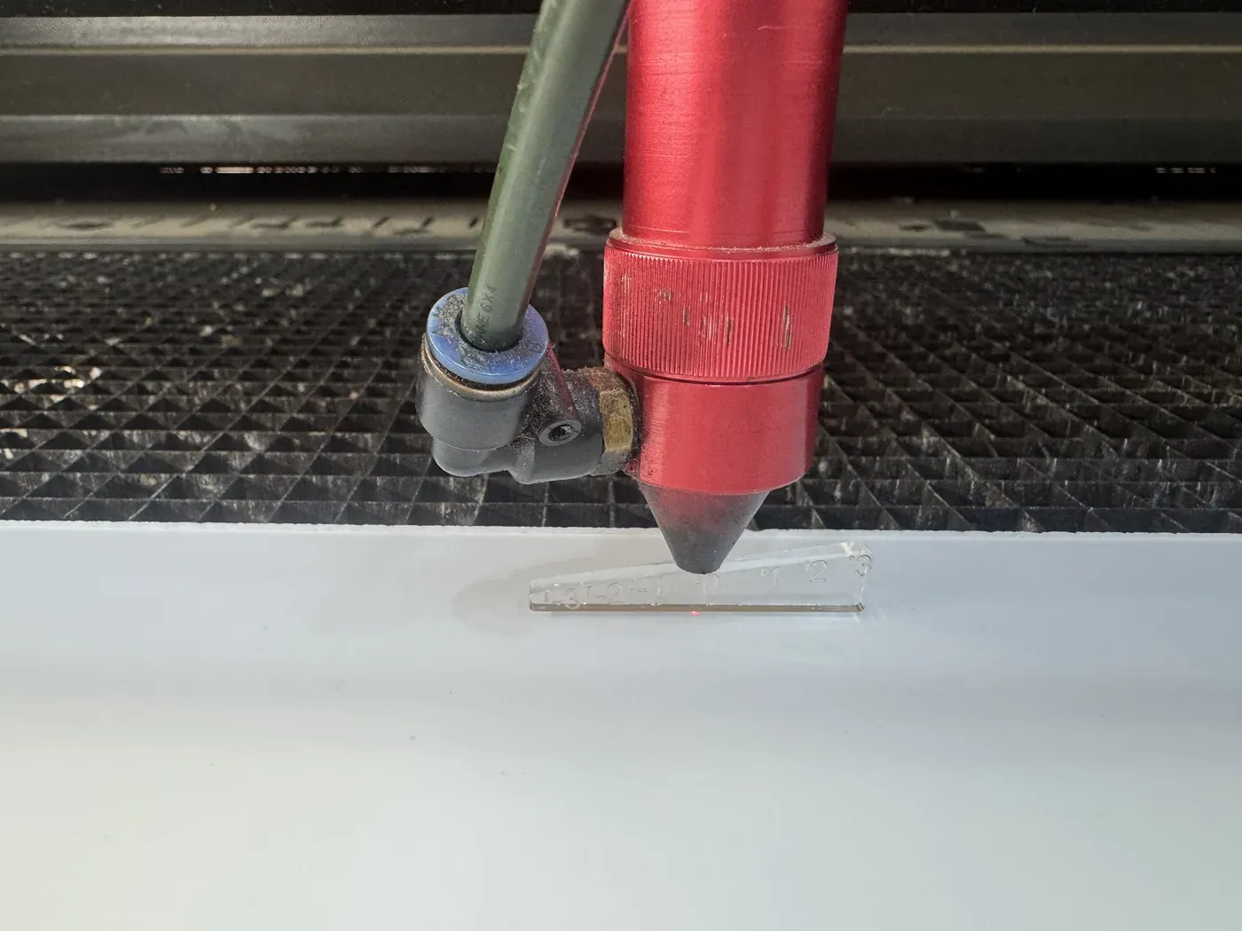
Setting nozzle height with the focusing gauge
The laser cutter in action, cutting the cat head waffle pieces
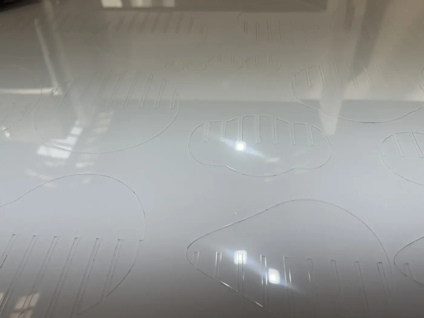
Freshly cut, pieces still nested in the sheet
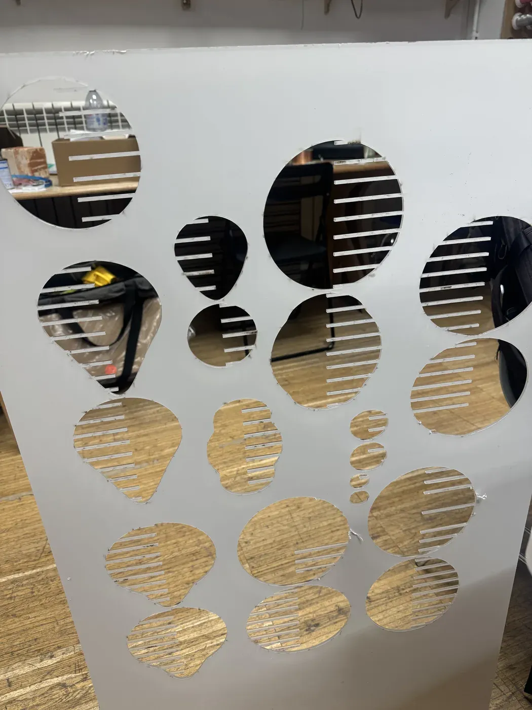
The sheet after popping out all pieces
Step 4: Assembly
Putting acrylic waffle pieces together is not for the faint of heart. The material is brittle, unforgiving, and has sharp edges; I cut my hand a few times. But the final result was worth it. For joint clearance I used the 3mm slot against the real 3.18mm acrylic; the kerf made up the difference for a snug friction fit with no glue.
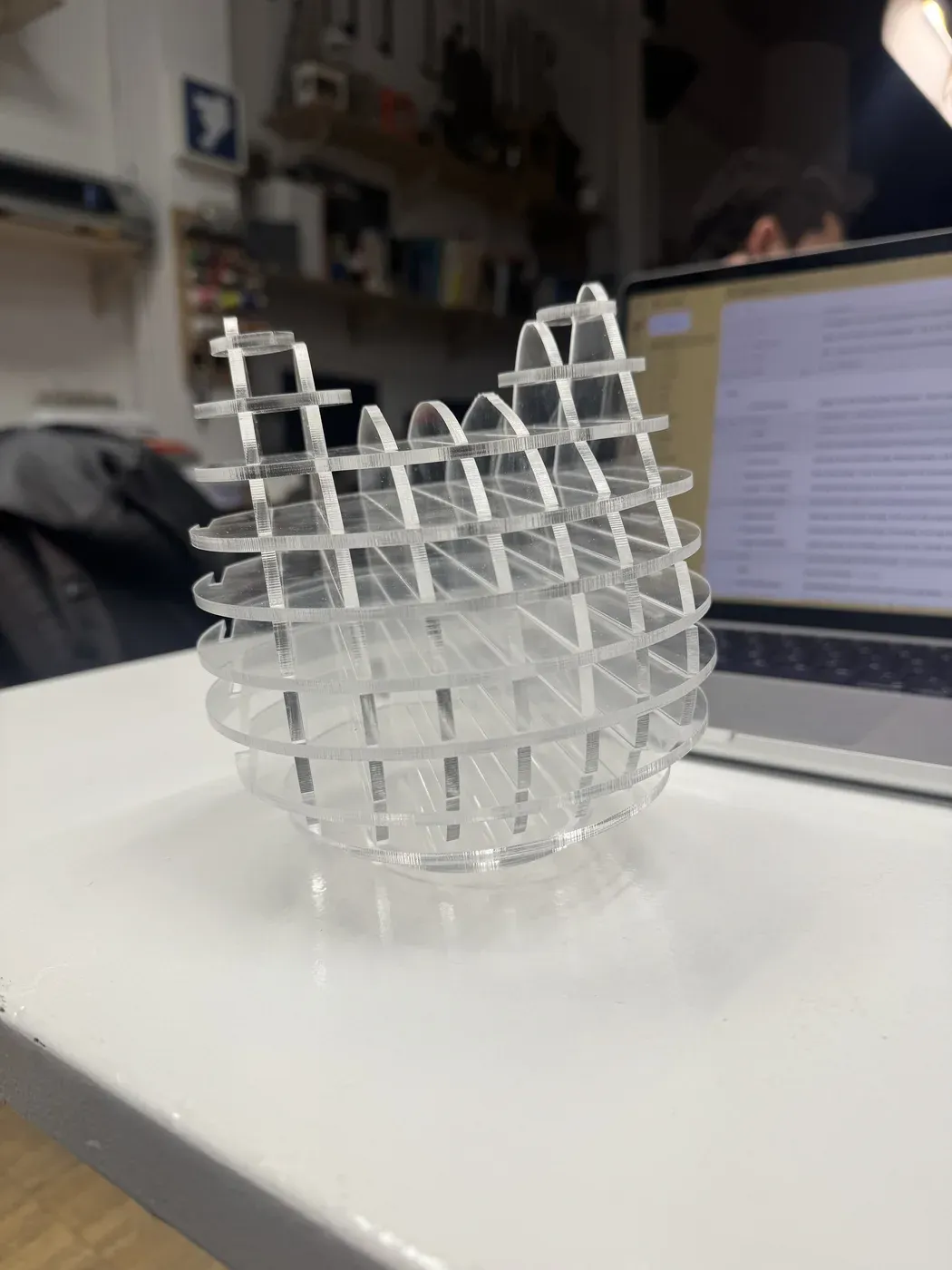
The finished cat head; clear acrylic waffle structure, abstract but instantly recognisable ✨
Experiment 4: Laser-Cut Tortilla
Yes, you read that right. I laser-cut a tortilla.
Finding the Parameters
Tortillas don't come with a material spec sheet, so I ran multiple test cuts to dial in the settings. Different brands = different thicknesses = different settings. If you switch brands, re-test!
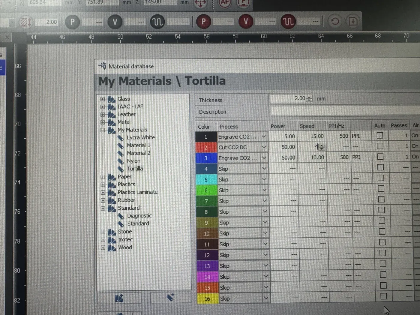
"Tortilla" is now officially in the material database 🌮
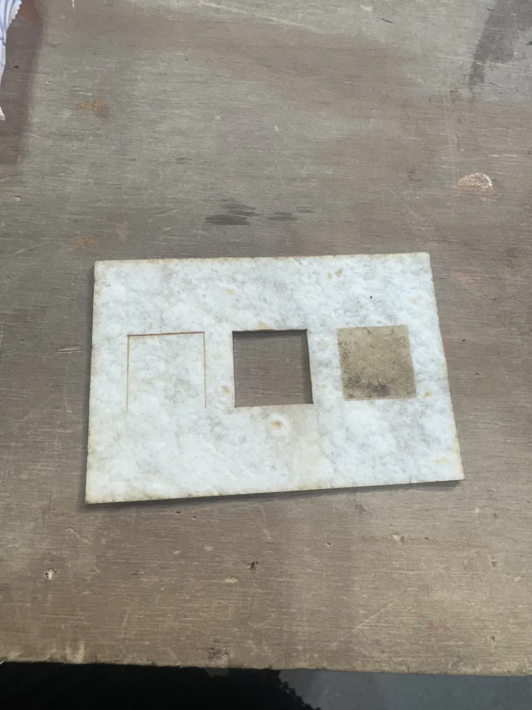
Test piece: score (left), cut (centre), engrave (right)
Laser cutting a tortilla
The Design
I'm designing an interlocking hexagonal pattern of circles that, when assembled, would create a waterproof custom burrito shell engraved with common flora found in Spain, a tribute to the country and one of its iconic foods.
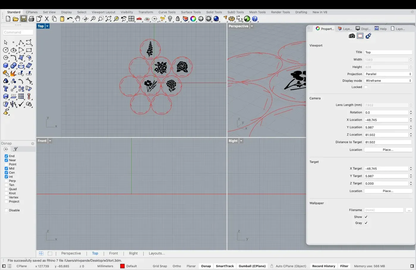
Hexagonal interlocking circles with flora engravings
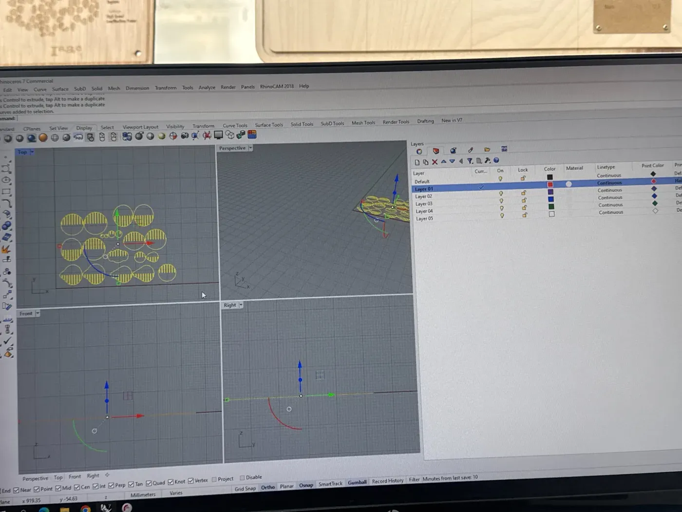
Colour-coded layers in Rhino; tortilla samples on the desk above
Status: Work in Progress. The interlocking is tricky because laser-cut tortilla gets slightly charred and brittle at the edges, so the notches need to be thick enough to hold without snapping. The quest for the perfect fabricated burrito continues.
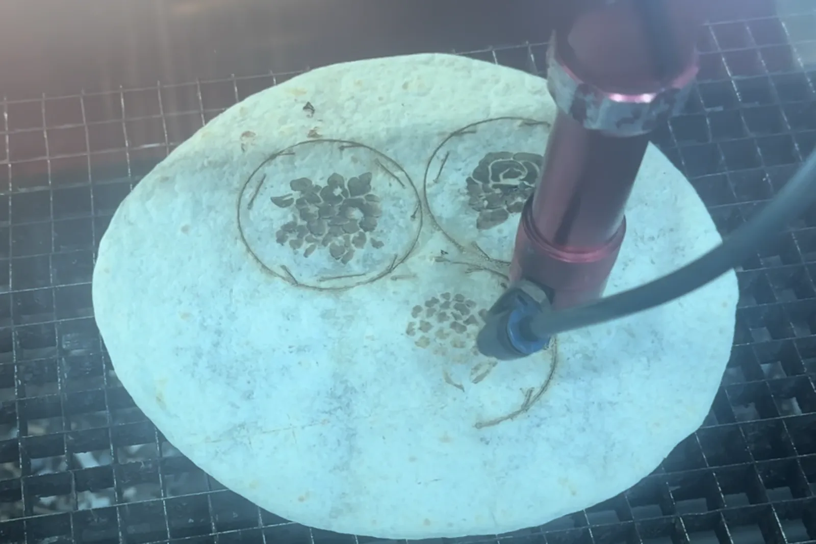
Cutting and engraving a tortilla in depth
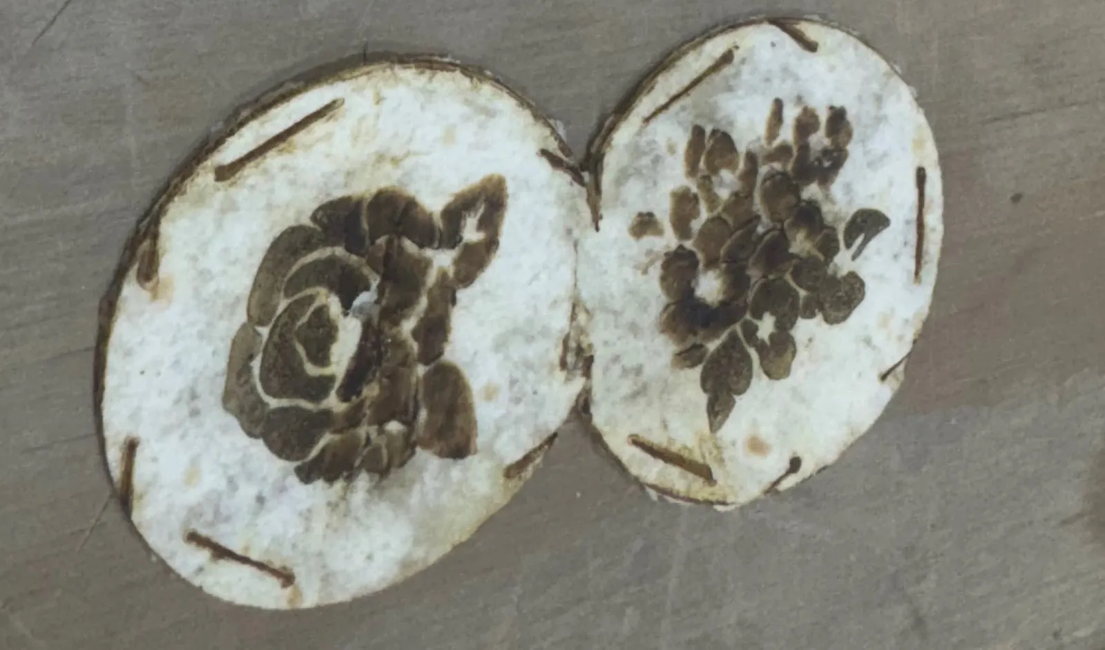
Making inter-lockable engraved modular tortillas
Parametric Design: Grasshopper vs. Geometry Nodes
Blender's Geometry Nodes clicked with me immediately, the workflow of connecting boxes felt natural, and I had familiarity from using the displacement modifier last week. If I had to choose one tool going forward, this would be it.
Grasshopper (Rhino) was interesting conceptually, same node-based approach, but the interface frustrated me. It opens as a panel on top of Rhino, and switching between the two felt clunky.
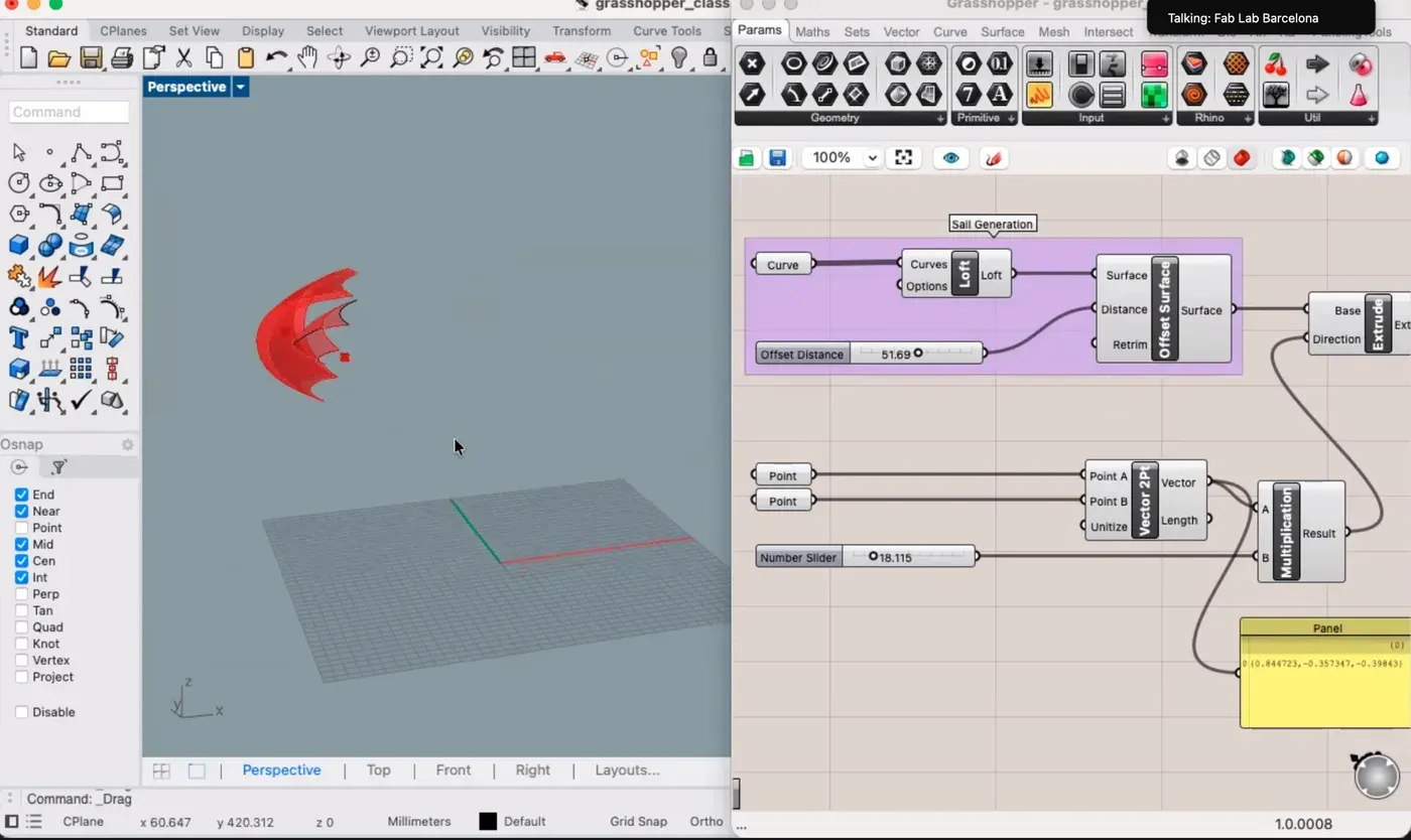
Grasshopper's node graph (Curve → Loft → Offset Surface → Extrude) generates the sail form. Powerful, but split-screen felt less intuitive than Geometry Nodes.
Reflections
This was one of the most hands-on weeks yet. Four experiments across two machines, each teaching a different lesson about material behaviour. The copper tape circuit brought together vinyl cutting, electronics, and my grandmother's art. The kerf test showed why you should never trust a label ("3mm" was actually 3.18mm). The cat head taught me that one pixel can kill a job. And the tortilla? It taught me as much about material science as the acrylic did. Maybe more.
"Test before you commit. Parametric thinking saves time. And always embrace the absurd, that's where the best learning hides."