Overview
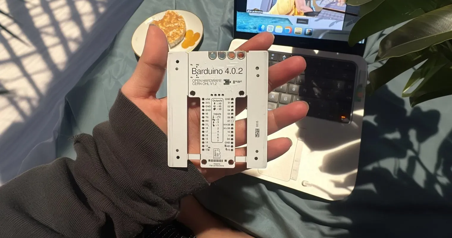
This week was about embedded programming writing code that runs directly on a microcontroller, close to the hardware. Think of it as programming from the 1950s and 60s: you're talking to the metal, not to an operating system. We worked with the Barduino (Barcelona's custom Arduino board, built around the ESP32-S3 microcontroller), learned to read datasheets without losing our minds, and I turned a circuit board into a Hindustani classical music instrument.
Three experiments this week: mapping musical frequencies to a buzzer, turning capacitative touch sensors into playable instrument keys, and discovering that RGB LEDs have a mind of their own. Plus, I built a repeatable system for reading datasheets and figured out exactly how Barduino fits into Maya's Mirror.
"A datasheet is a dictionary, not a novel. You look up what you need, not read it front to back."
Key Concepts
A Brief History of Computing
The word "computer" originally meant a person typically women who performed calculations by hand for nuclear research. It was considered lower-status work, so it was left to women. When the job was mechanised (again, largely by women), men moved in. The first programmers were all women. Computers don't even need to be digital; we once had mechanical computers. Thanks to Moore's Law, the computing power that once filled a room now fits on a chip smaller than your thumbnail.
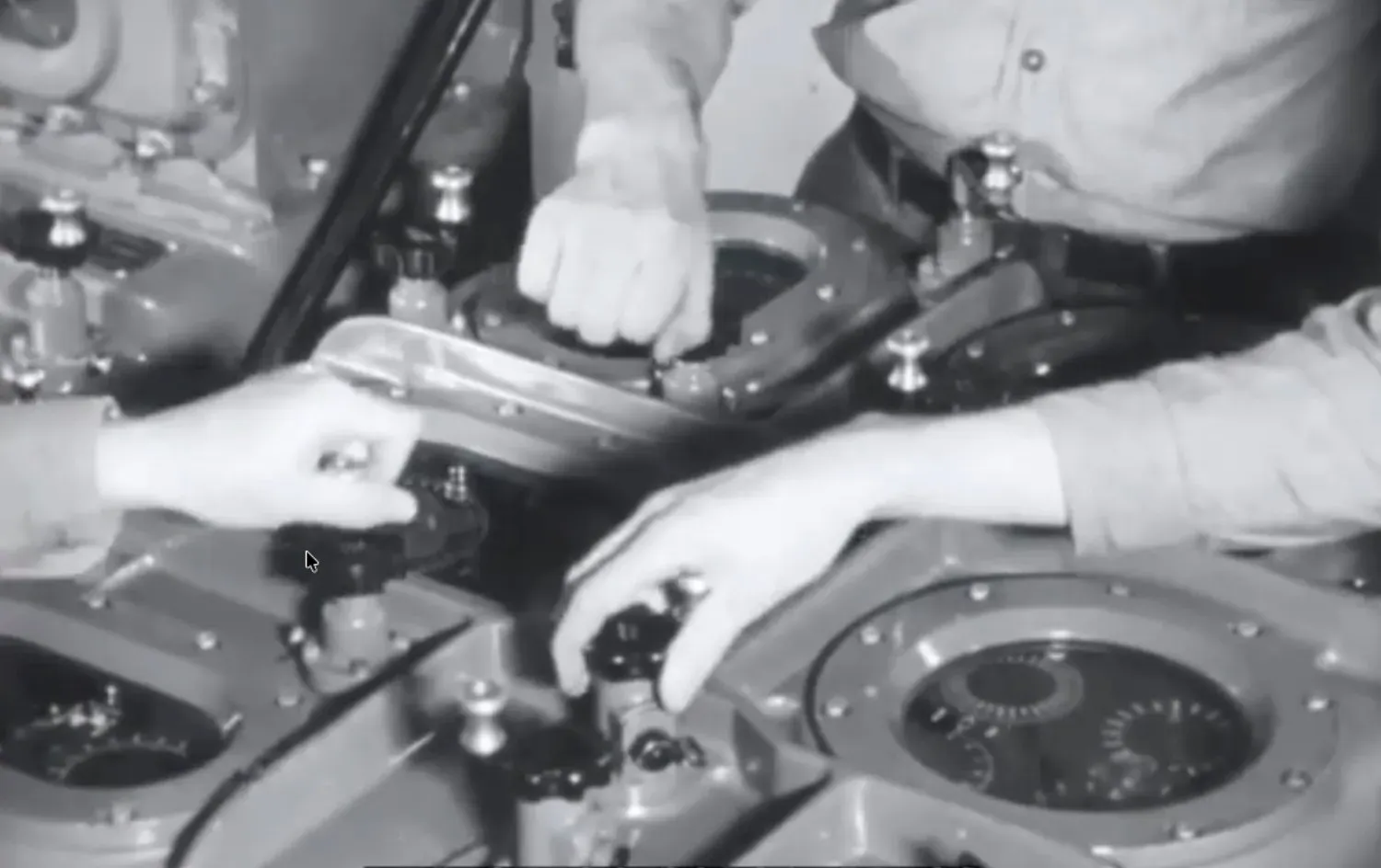
Mechanical computing in the 1950s: before silicon, calculations were physical
Microcontroller vs. Computer
A Raspberry Pi is essentially an entire computer for ~$10, it can run an operating system. An Arduino (or Barduino) runs a single program. That's the key distinction: a computer runs an OS, a microcontroller runs your code and nothing else. The core architecture is the same though: CPU ↔ Memory ↔ Input/Output, all connected by a bus.
Compiled vs. Interpreted
Arduino uses C (compiled), the code is translated into machine language (assembly) before it runs. MicroPython is interpreted, translated line-by-line as it executes. Compiled code runs faster; interpreted code is easier to debug. Think of it as reading a fully translated book (compiled) versus having a live interpreter whispering in your ear (interpreted).
The Building Blocks
- PCB: Printed Circuit Board ; the green (or any colour) board everything sits on
- IC: Integrated Circuit — the black chip you see on boards
- Microcontroller: The brain inside the IC that runs your program
- GPIO: General Purpose Input/Output — the pins you connect things to
The Microcontroller Garage
Our instructor used a brilliant vehicle analogy to explain the microcontroller ecosystem. Each chip is a different vehicle, you pick based on where you're going:
- CH32: The scootie — bare minimum, 20 MHz, insane 600-page datasheet for something so tiny
- ATtiny: The scooter — small, simple, gets you there
- SAMD: The Volkswagen — reliable daily driver, good balance of power and simplicity
- ESP32: The SUV — WiFi, Bluetooth, plenty of GPIO, handles most terrain (this is what Barduino uses)
- Raspberry Pi 2040: The Ferrari — maximum capacity, for when you need serious horsepower
Communication Protocols (The Social Lives of Chips)
Chips talk to each other and to the world through protocols. The analogy that stuck with me:
- I2C (Inter-Integrated Circuit): Like a monitor — structured, takes turns, everything goes through one shared bus. Uses SDA (data) and SCL (clock) lines.
- SPI (Serial Peripheral Interface): Like a fast gossiper — dedicated lines mean parallel communication. Uses MOSI (Master Out Slave In), MISO (Master In Slave Out), SCK (clock), and SS (Slave Select).
- ADC (Analog-to-Digital Converter): Like an empath — listens to the continuous analogue world (temperature, light, sound) and translates it into digital numbers the chip can understand.
-
UART (Universal Async
Receiver Transmitter): The print messenger —
TXD sends, RXD receives. This is what
Serial.println()uses.
Reading a Pinout Diagram
When reading pinout diagrams in datasheets, colours tell you what each pin does at a glance. Here's the ATtinyX14, a "scooter" chip, with its full colour legend:
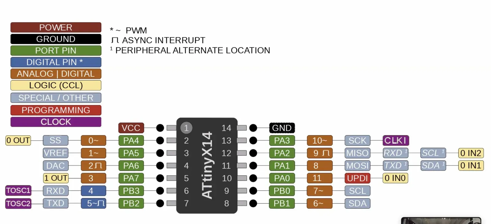
ATtinyX14 pinout: each colour indicates pin function: red (power), black (ground), green (port), blue (digital), orange (analogue), yellow (logic), purple (clock)
And here's the SAM D11C, a "Volkswagen" chip, with a similar layout but more pins and capabilities:
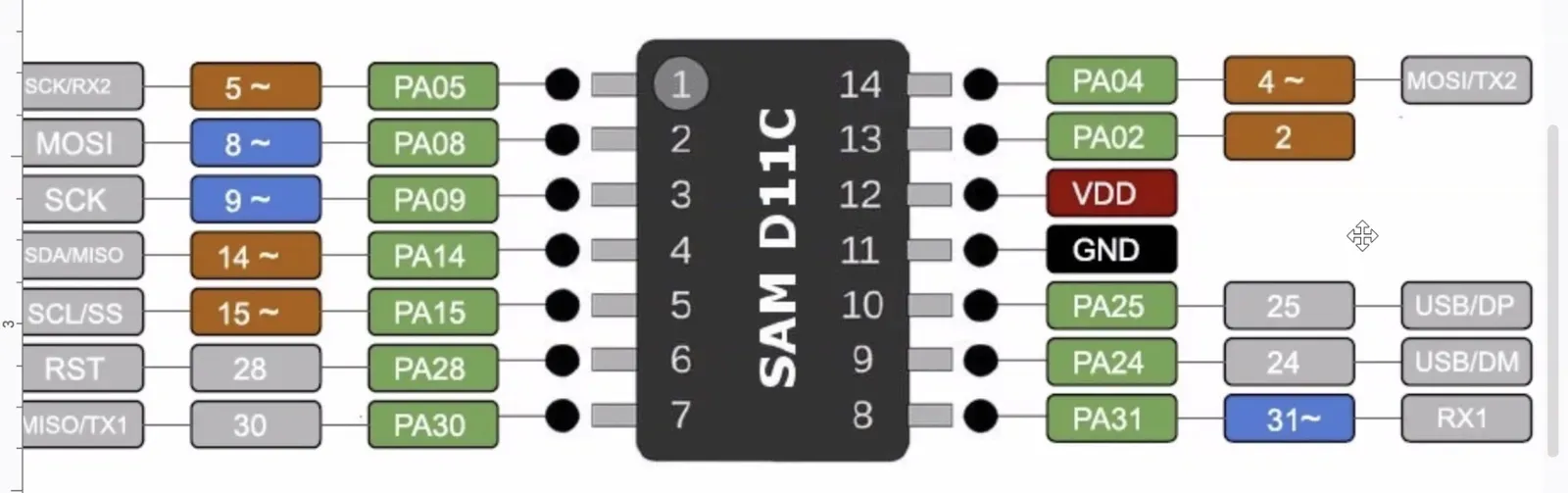
SAM D11C pinout: notice the same colour system, once you learn to read one pinout, you can read them all
The colour code cheatsheet:
- Red — VCC (power in)
- Black — GND (ground)
- Green — Port pins (PA0–PA7, PB0–PB7, 8 bits per port group)
- Blue — Digital pins (Arduino-style)
- Orange — Analogue-capable (can read analogue or digital)
- Yellow — Special logic (CCL — internal I/O for SPI, I2C, UART)
- Purple — Clock pins (time-related)
- Tilde (~) — PWM capable (Pulse Width Modulation)
Digital vs. Analogue
Digital is binary: HIGH or LOW, 1 or 0, on or off. Like a light switch. Analogue is a range: like a dimmer. Temperature, light intensity, and sound are all analogue, they have magnitude and gradation, not just on/off states. ADC pins bridge this gap, converting analogue signals into digital values your microcontroller can process.
Setting Up Barduino
Barduino is Fab Lab Barcelona's custom board. It uses the ESP32-S3 microcontroller by Espressif, but speaks the Arduino language through the Arduino IDE. Same software, different (and more powerful) hardware.
IDE Configuration
Getting the Arduino IDE to talk to Barduino required a few specific settings:
- Paste the ESP32 board manager URLs in Preferences (for compiling and uploading)
- Install ESP32 by Espressif from the Board Manager
- Select ESP32S3 Dev Module as the board
- Set the correct port
- Enable verbose output for compilation and upload, this is how you actually see what went wrong
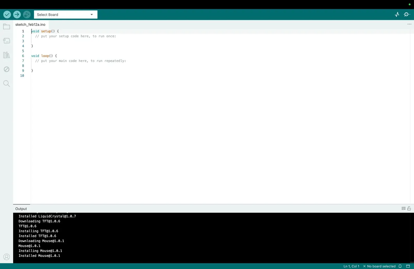
Arduino IDE with the two default functions:
void setup() (runs once) and
void loop() (runs forever). The
output panel shows libraries being installed.
The Two Default Functions
Every Arduino sketch has two functions:
void setup() runs
once at the start (declare your pins here), and
void loop() runs
forever after that (your main program logic).
Think of setup() as tuning your
instrument before a concert, and
loop() as actually playing.
Barduino Pinout
The back of the Barduino board has the full pinout printed on it. But the detailed technical pinout diagram shows every function each pin supports: GPIO, ADC, touch, I2C, SPI:
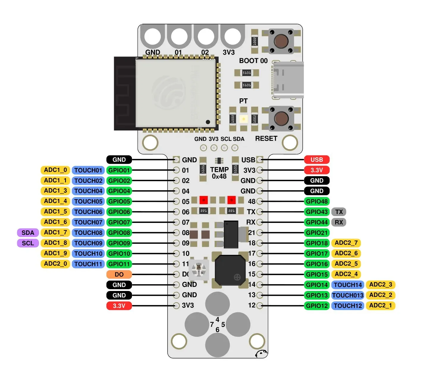
Barduino full pinout: left side has the touch sensors (TOUCH01–TOUCH11) and ADC channels; right side has the main GPIO, TX/RX, and power. The bottom pads (4, 5, 6, 7) are the capacitative touch buttons.
The pins I used most this week:
- Pin 48: Built-in LED + NeoPixel strip (output)
- Pin 46: Buzzer (output) mapped to the 🔊 icon
- Pin 38: RGB LED (output) the 🌈 icon
- Pin 3: Light sensor (input)
- Pins 1, 2, 4, 5, 6, 7: Capacitative touch sensors (input)
- I2C (SDA/SCL): Temperature sensor at address 0x48
- Pin 0: Button (input)
Critical Gotcha: USB CDC on Boot
This one cost me time: USB CDC on Boot must be set to "Enabled" in the Arduino IDE for Barduino. It's disabled by default. Without it, your code uploads fine but nothing happens. Also, if your code compiles, uploads, shows no errors, but still doesn't run? Try the physical reset button on the board. Sometimes hardware just needs a reboot.
Core Arduino Functions I Used
A quick reference for the functions that powered this week's experiments:
-
pinMode(pin, OUTPUT)Declare a pin as output (insetup()) -
digitalWrite(pin, HIGH/LOW)Turn a pin on or off -
tone(pin, frequency)Start playing a sound: which pin, what pitch (Hz). Keeps playing untilnoTone()is called. -
noTone(pin)Stop the buzzer. Essential, without it, the tone keeps playing forever. -
delay(ms)— Pause execution for a number of milliseconds -
touchRead(pin)— Read the capacitative touch value from a sensor. Returns a number; higher = finger detected. -
analogRead(pin)— Read an analogue value from a sensor -
strip.setPixelColor(i, Color)— Set a NeoPixel's colour in the buffer (Adafruit NeoPixel library) -
strip.show()— Push the buffer to the physical LED strip. Nothing changes until you call this. -
strip.clear()— Zero out all pixels in the buffer. Call before each frame, or old LEDs stay lit. -
Serial.println("text")— Print to the serial monitor for debugging (note:Serialhas a capital S)
"The syntax for serial tripped me up at first:
Serial is capitalised (like a proper
noun), but everything else is camelCase. Little
details that matter when a missing capital letter
means your code doesn't compile."
Experiment 1: Sa Re Ga Ma, Hindustani Classical Music on a Buzzer
My first experiment was mapping the swaras (notes) of Hindustani classical music to specific frequencies and playing them through Barduino's buzzer. Sa, Re, Ga, Ma, Pa, Dha, Ni, Sa: the Indian equivalent of Do, Re, Mi.
Mapping Frequencies
Using the tone() function, I mapped
each swara to a frequency. The
tone(pin, frequency, duration)
function made this straightforward, pin 46
(buzzer), the frequency in Hz, and duration in
milliseconds. I noted all the frequency-to-swara
mappings in my notebook so I could reference
them while composing.
Playing Songs
By stringing together sequences of
tone() and
delay() calls inside
void loop(), I was able to play
recognisable melodies. The scale wasn't
perfectly tuned (I'm a designer, not a
musician), but it was thrilling to hear actual
songs come out of a circuit board.
Hindustani swaras playing through Barduino's buzzer, Sa Re Ga Ma Pa in code 🎵
Playing a Full Song
Once I had the individual swaras mapped, I
strung them together into a full melody,
sequencing tone() and
delay() calls to match the rhythm.
It's not concert-grade, but hearing a
recognisable song come out of a circuit board
you programmed yourself is a different kind of
magic.
Playing a full song on the Barduino buzzer, each note programmed as a tone() call 🎶
Experiment 2: Touch Sensor Instrument
Building on Experiment 1, I mapped six capacitative touch sensors on the Barduino to six swaras: Sa, Re, Ga, Ma, Pa, and Ni. Each touch pad became a playable "key": touch it, and the LED lights up while the buzzer plays the corresponding note.
Pin-to-Swara Mapping
Each touch pin got assigned a swara and its corresponding frequency:
- Pin 4 → Sa (262 Hz)
- Pin 5 → Re (294 Hz)
- Pin 6 → Ga (327 Hz)
- Pin 7 → Ma (349 Hz)
- Pin 2 → Pa (392 Hz)
- Pin 1 → Ni (491 Hz)
Adaptive Baseline Calibration
The clever part of this code is the adaptive baseline. Capacitative touch values drift with temperature, humidity, and even how long the board has been on. A fixed threshold would stop working after a few minutes.
The solution: on boot (with a 500ms
delay() — don't touch anything!),
the code reads each sensor's resting value as
its baseline. A touch is detected when the
reading exceeds
baseline + 50,000. When no
finger is touching anything, the baselines
slowly update using an exponential moving
average:
baseline = (baseline × 9 + currentValue) /
                                    10
. This means the instrument self-calibrates
over time, it keeps working even as conditions
change.
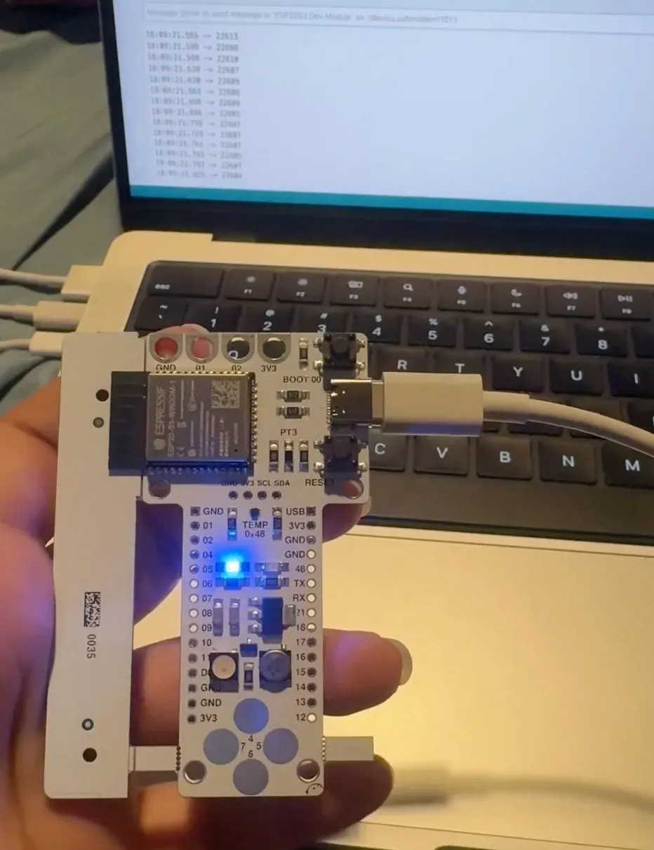
Barduino connected to the serial monitor: touch values streaming in real time (the numbers on screen). When a value spikes above baseline + 50,000, it registers as a touch and the LED lights up.
Playing It
The LED on pin 48 gives visual feedback, it
lights up whenever a touch is detected and goes
dark when released. noTone() stops
the buzzer when no finger is touching any pad.
The 20ms delay() at the end of each
loop acts as a debounce, preventing the sensor
from firing multiple times on a single touch.
The Barduino as a musical instrument: six touch sensors playing Hindustani swaras in real time 🎶
Experiment 3: NeoPixel LED Strip: The Light That Won't Turn Off
For the third experiment, I drove a strip of 13 NeoPixel LEDs on pin 48 using the Adafruit NeoPixel library. A simple red chase animation, one LED lights up at a time, running down the strip, but it taught me the most important lesson of the week.
The Discovery
The NeoPixel library works with a
buffer: you set pixel colours
in memory, then push the entire buffer to the
strip with strip.show(). Nothing
changes on the physical LEDs until you call
show(). And here's the critical
part:
strip.clear() is essential
before each frame. Without it, previously lit LEDs stay on
because the strip holds its last state. You
don't get a chase animation, you get a growing
red bar.
This is the same lesson from a different angle:
hardware doesn't reset itself. In a CSS
animation, the browser handles cleanup between
frames. In embedded programming, you
are the cleanup.
strip.clear() is your garbage
collector.
NeoPixel chase: red light running across 13
LEDs, with strip.clear() before
each frame to prevent the "growing bar" effect
"In UI design, everything resets to a default state. In embedded programming, there are no defaults, only the last thing you told the hardware to do. You are the garbage collector."
My 5-Step Datasheet Reading System
Datasheets are terrifying. The ESP32-S3 technical reference is 700+ pages. The CH32's is 600 pages for a chip the size of a grain of rice. But I developed a system that cuts through the noise: treat the datasheet as a dictionary, not a novel.
Step 1 in Action: "What Is It?"
You only read the first page. The title and "Features" box tell you what the chip does. If it doesn't match your project need, stop here. Here's what that looks like for two chips we studied:
ESP32 datasheet cover: title and version tell you everything at a glance
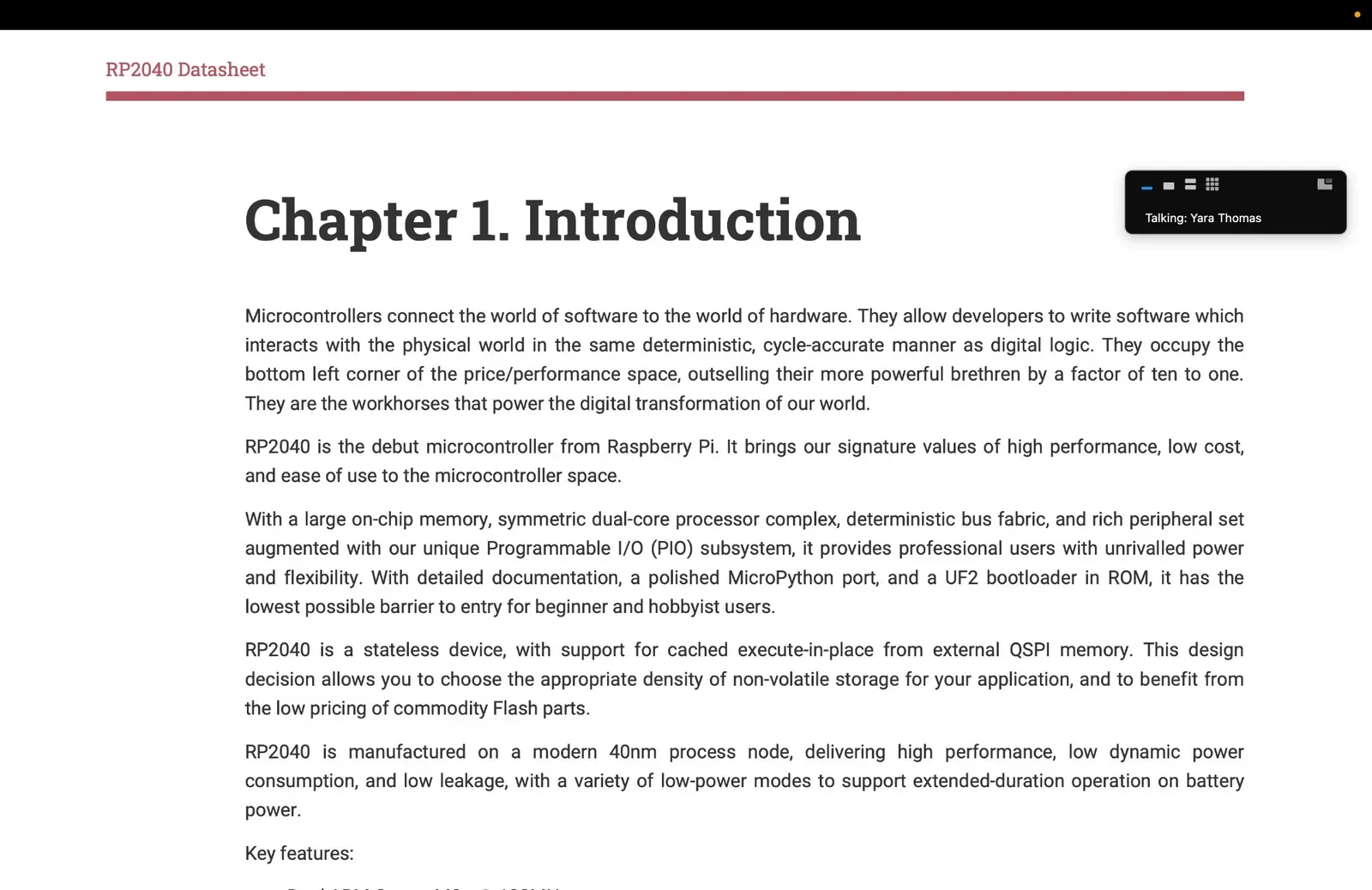
RP2040 datasheet intro: dual-core, MicroPython, low cost, the "Ferrari" chip
The Full 5 Steps
- Step 1 — WHAT IS IT? Read only the first page. Title + "Features" box. Does it match your project? If not, stop.
- Step 2 — PINOUT: Find the pin diagram, this is your wiring map. Mark power, ground, data, analogue, digital.
- Step 3 — ABSOLUTE MAXIMUMS: The "don't kill it" table. Max voltage, max current, operating temperature. Hard walls, exceed them and the chip dies.
- Step 4 — ELECTRICAL CHARACTERISTICS: The "happy zone" table. Operating voltage, typical current, logic levels. This is where you design your power supply.
- Step 5 — COMMUNICATION: How does it talk? I2C, SPI, UART, WiFi? What address? What speed? This determines your wiring and code.
The 3-Question Framework
For every single component, I now ask three questions:
- "What do I feed it?" → voltage, current requirements
- "How do I talk to it?" → protocol, pins, address
- "What does it give me back?" → output type, data range, units
Everything else in a datasheet is edge cases you look up when you hit a specific problem. This system saved me from reading 700 pages, I read ~15 across 6 sections and got exactly what I needed.
Barduino × Maya's Mirror: The Architecture
The biggest question I came into this week with: can this chip run my final project? Maya's Mirror needs real-time face tracking (MediaPipe), canvas drawing (botanical art compositing), and WebSocket communication. The answer is nuanced.
Note: I learned embedded programming this week on the Barduino, but my final project runs on the XIAO ESP32-S3 — a smaller board built on the same ESP32-S3 chip. Everything below (the datasheet findings, the WiFi-server architecture, the GPIO/WebSocket plan) transfers directly from the Barduino to the XIAO, since they share the chip. I just move to the smaller footprint for the installation.
The Verdict: Yes — As a WiFi Web Server
The ESP32-S3 can't run face tracking (that needs a GPU), but it can host the web page that runs everything in the viewer's browser:
┌─────────────────────────────────────────────┐
│            BARDUINO (ESP32-S3)              │
│                                             │
│  ┌─────────────┐   ┌────────────────────┐   │
│  │ WiFi AP     │   │ Web Server         │   │
│  │ "MayaMirror"│──▶│ Serves HTML/JS/CSS │   │
│  └─────────────┘   └────────────────────┘   │
│                                             │
│  ┌─────────────┐   ┌────────────────────┐   │
│  │ WebSocket   │◀─▶│ GPIO Control       │   │
│  │ /ws endpoint│   │ LEDs, button, etc  │   │
│  └─────────────┘   └────────────────────┘   │
└──────────────────────┬──────────────────────┘
                       │  WiFi connection
                       ▼
┌─────────────────────────────────────────────┐
│         VIEWER'S PHONE / TABLET             │
│                                             │
│  Browser loads page from Barduino           │
│  ┌─────────────────────────────────────┐    │
│  │ MediaPipe Face Mesh (478 landmarks) │    │
│  │ Canvas 2D botanical drawing         │    │
│  │ WebSocket sends stage events back   │    │
│  └─────────────────────────────────────┘    │
└─────────────────────────────────────────────┘
Architecture: the ESP32-S3 hosts the WiFi network and serves the web app; the viewer's browser does all the heavy computation
What the ESP32-S3 CAN Do
- Host a WiFi network (SoftAP mode) — viewers connect to "MayasMirror" and open 192.168.4.1 in their browser
- Serve static files from SPIFFS/LittleFS — HTML, CSS, JS all stored on the ESP32's flash. No internet needed.
- GPIO for physical triggers — a button to start/reset, LEDs that react to stage transitions, a proximity sensor for auto-trigger
- WebSocket communication — real-time two-way data. Browser tells the board "stage 3 started" → board triggers LEDs, motors, or sound
What the ESP32-S3 CANNOT Do
- Run MediaPipe face tracking — face mesh with 478 landmarks requires a GPU/CPU far beyond ESP32's capabilities
- Run the canvas drawing — the botanical art rendering is Canvas 2D, a browser feature
- Stream video — ESP32-CAM exists but can't handle real-time face mesh processing
Datasheet Sections I Actually Needed
Applying my 5-step system to the ESP32-S3 datasheet for Maya's Mirror:
- Features (p.1): WiFi 802.11 b/g/n, 2.4GHz, confirmed it can host a local access point
- Pin Functions: 45 GPIOs — more than enough for LEDs + button + sensor
- WiFi specs: SoftAP mode supports up to 10 stations
- Flash/PSRAM: 8MB flash on Barduino, plenty for HTML/JS/CSS files
- Operating voltage: 3.3V logic, powered via USB-C
- PWM: 8 LED PWM channels for smooth RGB strip fading
Sections I skipped entirely: Bluetooth classic, touch sensor calibration, deep sleep modes, security encryption, JTAG debugging, RTC memory. None relevant to this project.
What I Still Need to Build
- Flash the Maya's Mirror HTML/JS to the XIAO ESP32-S3's LittleFS
- Write Arduino code for WiFi AP + web server + WebSocket
- Wire a physical button (start/reset trigger)
- Optional: LED strip that shifts warm white → teal → pink across stages
- Optional: Proximity sensor to auto-trigger when someone approaches
- Test on a tablet mounted behind a two-way mirror
Bonus: The Xiao
We also looked at the Xiao (X-I-A-O), a microcontroller so small it looks like a baby USB stick. It fits in your palm, has everything built in, and is genuinely impressive, like an iPhone: it just works, but good luck understanding why. Great for beginners wanting quick results; less great if you want to understand what's happening under the hood. For someone learning fabrication, I found more value in working with the Barduino where every connection is visible and intentional, then moving to the XIAO ESP32-S3 for my final project once I understood the chip.
Digital Simulation
For testing circuits without physical hardware, we
can use Wokwi (linked in the sidebar) a
browser-based simulator for Arduino, ESP32, and
other microcontrollers. It's incredibly useful for
prototyping logic before committing to a physical
build, especially when you're iterating on
tone() frequencies and don't want to
annoy everyone in the lab with a buzzer loop.
Group Assignment: What I Took Away
Our group compared the toolchains and development workflows for the boards in our lab, the full comparison lives on the group work page (linked in the sidebar). I took part as a hands-on observer rather than driving a board myself, but the comparison reframed how I think about embedded work.
My main takeaway: the toolchain is separate from the board. The same Arduino IDE drives completely different upload paths depending on the target, SerialUPDI for the ATtiny, CMSIS-DAP over SWD for the Barduino, and a programmer can even be used to flash another programmer. Seeing that side by side is what made the "which chip, which workflow" decision concrete for my own work this week on the ESP32-S3.
Reflections
This week bridged two worlds for me: software and hardware. As a product designer, I'm used to things having default states, auto-saving, and error handling built in. Embedded programming strips all of that away, if you don't tell the LED to turn off, it stays on. If you don't declare a pin as output, nothing happens. There's a raw honesty to it.
The highlight was turning the Barduino into a Hindustani classical instrument. The adaptive baseline calibration, where the sensor thresholds slowly drift to match environmental changes, felt like giving the instrument a kind of self-awareness. There's something deeply satisfying about hearing Sa Re Ga Ma come out of a circuit board you programmed yourself. The scale wasn't perfect, but the joy was.
Most importantly, I now know exactly how the ESP32-S3 fits into Maya's Mirror, not as the brain, but as the body. It hosts the WiFi, serves the web page, and controls the physical elements. The browser does the thinking. It's a clean separation of concerns, and it means the installation can be completely self-contained. No internet required, and it moves cleanly onto the XIAO ESP32-S3 for the final build.
"The datasheet reading system was the real unlock. 700 pages became 15. The rule is simple: start with your project's questions, then find the answers in the datasheet, never the other way around."