Overview
This week was about 3D scanning and printing : capturing the physical world as digital geometry, and then making digital geometry physical again. We worked across three printing technologies: FDM (filament), SLA (resin), and clay (a modified FDM with a clay cartridge instead of a hot end). On the scanning side, we used handheld structured-light scanners, Skanect software, and even phone-based photogrammetry.
Three projects this week: a resin-printed lattice cube that casts the letters F-A-B as shadows, a kulhad (traditional Indian chai cup) designed for clay printing using a Grasshopper-to-GCode pipeline, and 3D scanning classmates and objects with structured-light sensors and Kinect. Plus, I learned that resin printing is simultaneously the most precise and the most chaotic form of fabrication I've encountered so far.
"3D printing is thinking in slices. Every decision orientation, supports, infill comes down to: what does each layer need to rest on?"
Key Concepts
Types of 3D Scanning
Scanning reconstructs 3D geometry by measuring where surfaces collide with light, sound, or touch. The camera's own movement is tracked by an accelerometer, so the software knows where you are relative to the object. Different scanners suit different scales:
- Structured Light Scanners (SLS): Project patterned lines onto the surface. The distortion of those lines tells the software about depth and edges. Can scan metal. This is what we used in class.
- LIDAR: Echolocation for machines pulses of light measure distance by timing reflections. Used in self-driving cars, archaeology (the Maya civilisation in Guatemala was remapped using LIDAR), and surveillance. Modern iPhones have LIDAR built in. Produces a point cloud that can be converted into a DEM (Digital Elevation Model) to create terrain.
- Photogrammetry: Takes multiple photos from different angles and reconstructs geometry from pixel overlap. Use a smaller aperture to avoid overexposure. Your phone's accelerometer helps track position between shots.
- Touch/Digitiser Probes: Physical contact-based measurement for very small, precise items. A probe touches the surface point by point.
Scanning Tips (The Hard Way)
Glossy, transparent, or very dark surfaces don't scan well the light bounces unpredictably or gets absorbed. Quick fix: dust the object with baby powder or a mattifying spray. Think of scanning like taking a panorama photo: each pass needs about 30% overlap with the previous one. Gaps in coverage = holes in your mesh.
A good exercise: scan your hand in two positions : open and fisted. The fist (simple geometry) scans much cleaner than the open hand (thin fingers, occlusions between digits). This teaches you what scanners struggle with.
File Formats: The Translation Layer
Getting from scan to print requires knowing which format to use when:
- STL: The universal 3D printing format. Mesh-only, no colour or texture. Good for editing: you can fill holes, fix floating geometry, and repair surfaces.
- OBJ: Use when you need texture and colour information alongside the mesh. Better for scanned models you want to keep visually accurate.
- 3MF: A newer format that packages mesh, colour, and print settings together. Gaining adoption.
The pipeline: Scan → Clean mesh (fill holes, reduce noise) → Check watertight (no open edges) → Export as STL → Slice → Print. Your raw scan will always have noise, floating points, and holes. Tools like MeshLab or Meshmixer are essential for cleanup.
Types of 3D Printing
Three technologies, three trade-offs:
- FDM (Fused Deposition Modelling): Melted filament extruded layer by layer. Accessible, affordable, good for prototyping. But visible layer lines and limited resolution on fine details.
- SLA (Stereolithography / Resin): UV light cures liquid resin layer by layer. Extremely fine detail (0.050mm layers), smooth surfaces. But messy, requires chemical handling, and post-processing (wash + UV cure).
- Clay Printing: An FDM printer with the hot end removed and replaced by a clay cartridge with an air compressor. Can print with biomaterials, terracotta, food-safe clay, and experimental pastes. Unique to Fab Lab Barcelona.
Design Rules for 3D Printing
These rules apply across all printing technologies, though tolerances change:
- Layer orientation matters: Imagine holding a tree branch. Print it standing up and it snaps easily along the layer lines. Print it lying down and it's much stronger. Layer lines are always your weak point.
- Overhangs need support: Anything past ~45° needs support material. You can't print in mid-air, think of it like building a bridge.
- Walls: At least 2× your nozzle diameter (so ~0.8mm for a 0.4mm nozzle).
- Infill: 15–20% is fine for most things. 100% infill is almost never worth the time. Infill is like the inside of a chocolate truffle, you don't need it solid, just enough internal structure to hold its shape.
- Tolerance: Add ~0.2–0.3mm clearance for interlocking parts. The printer slightly over-extrudes, so parts designed to exact dimensions will be too tight.
- First layer is everything: If it doesn't stick, nothing else matters. Level your bed, dial in your Z-offset. The first layer should look like slightly squished lines, not round spaghetti.
3D Scanning
We used a handheld structured-light scanner connected to a phone, the phone's screen shows the real-time reconstruction while the sensor bar projects infrared patterns to capture depth. The setup is surprisingly compact: sensor bar, phone mount, and a single USB-C cable.
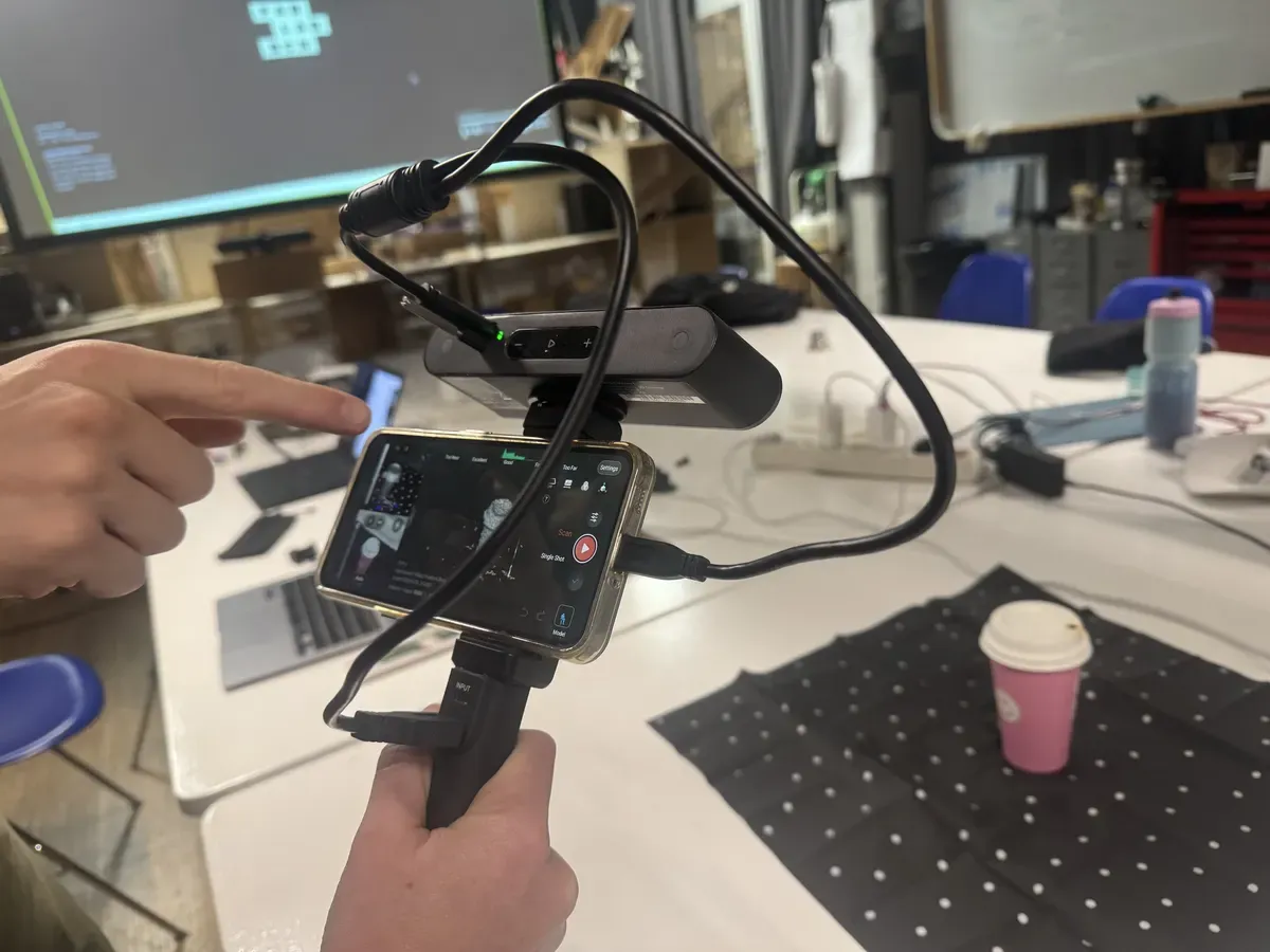
The scanning rig: a structured-light sensor bar mounted above a phone, with a pistol grip for smooth movement
Scanning a Coffee Mug
Our first scan was a coffee mug placed on a dotted reference mat. The dots give the scanner fixed reference points to track its position relative to the object. The instructor demonstrated the technique: slow, steady orbits around the object, always maintaining overlap between passes.
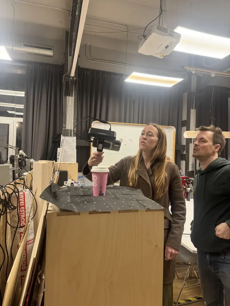
Scanning the coffee mug on a dotted reference mat, the dots help the scanner track its position
Full-Body 3D Scan
The more ambitious scan was a full-body capture of a classmate, who had to sit completely still while someone orbited them with the scanner. We used a Kinect sensor with Skanect to process the capture, it handles mesh reconstruction, hole filling, and cleanup. The result was a surprisingly detailed 3D model, capturing clothing folds and even shoe textures.
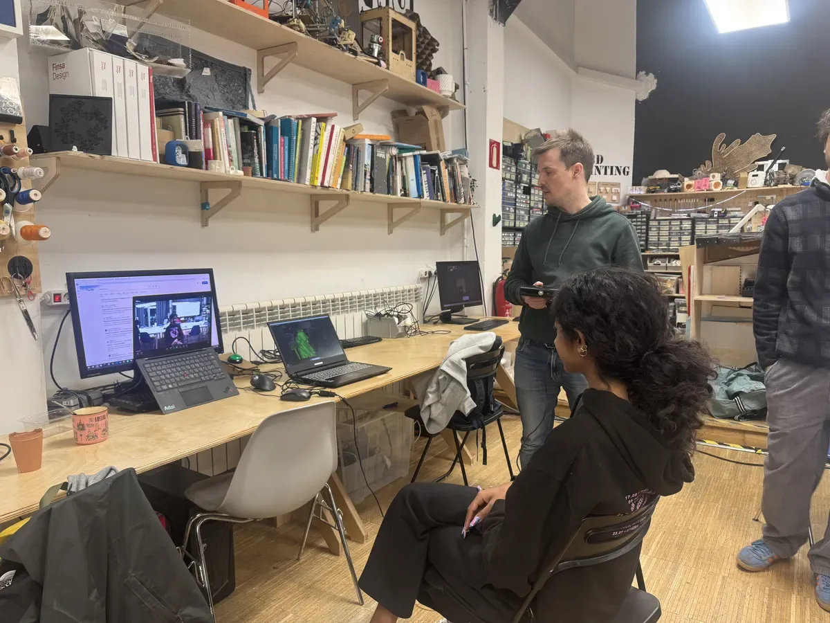
Scanning demo in the lab, the laptop shows the real-time point cloud as the scan builds up
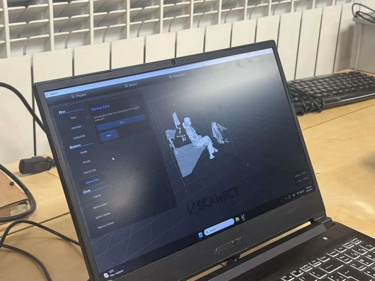
Skanect's Prepare tab: mesh cleanup tools for removing small floating parts, making the mesh watertight, and filling holes
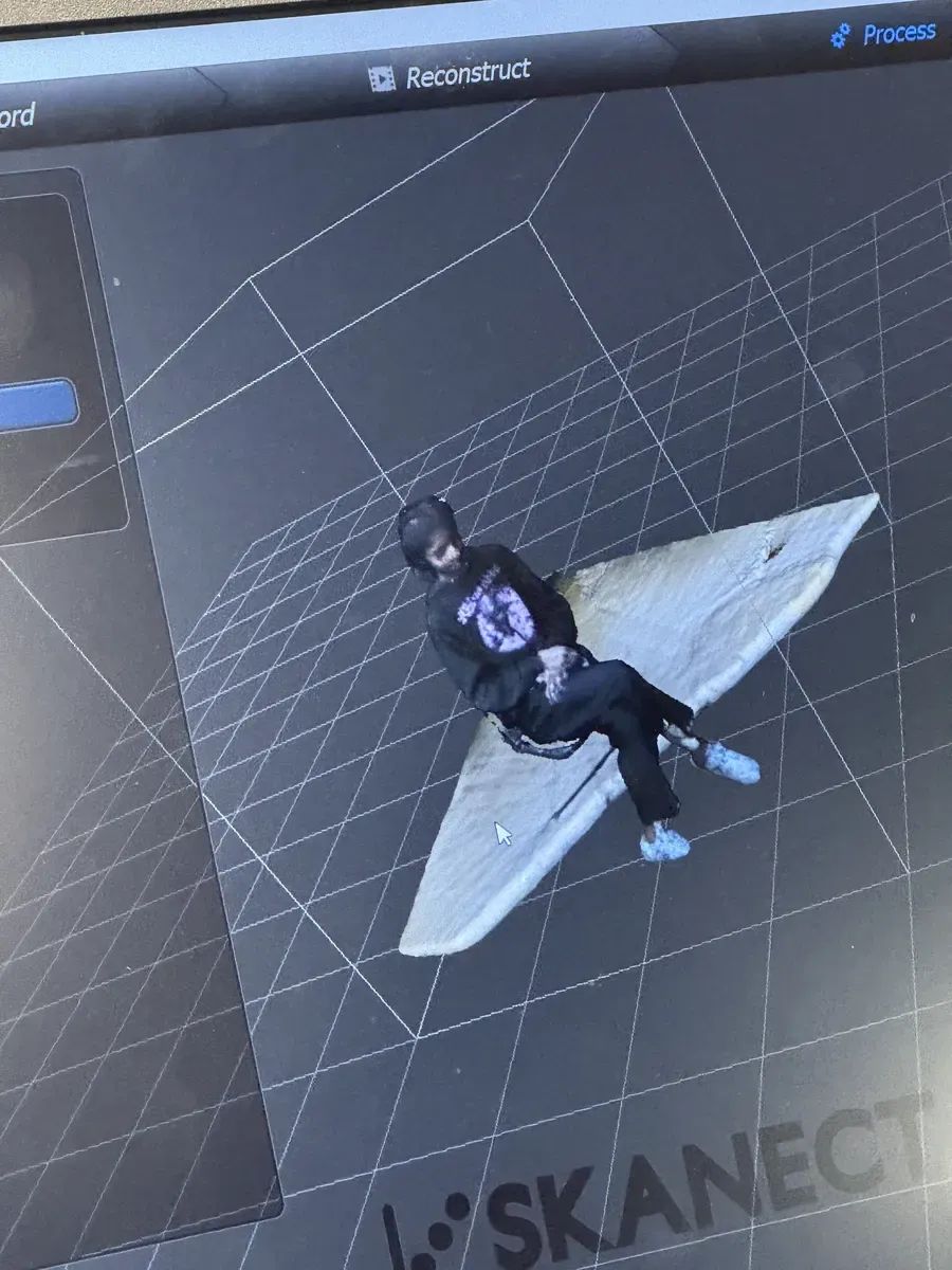
The reconstructed full-body scan, notice the detail in the clothing folds and the bench surface
Phone Photogrammetry with Polycam
We also experimented with Polycam, a phone-based photogrammetry app that uses your camera and accelerometer to reconstruct 3D models from photos. I scanned birthday pastries, you walk around the object, the app captures overlapping shots, and stitches them into a textured mesh. The result is surprisingly detailed for something done entirely on a phone, though you can see the mesh edges fraying at the plate boundary where scan coverage dropped off.
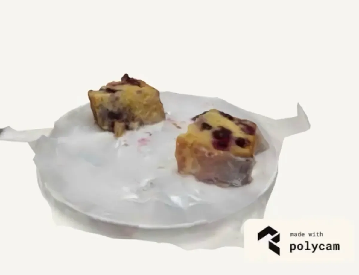
A Polycam scan of birthday pastries, notice the texture quality on the food versus the fraying mesh edges where coverage dropped off
Resin Printing: The FAB Shadow Cube
My main project this week was a 50mm lattice cube designed so that when you shine light through it from three different angles, the shadows spell out the letters F, A, and B. The object itself looks like an abstract grid, only the shadows reveal the hidden message. Inspired by works by DRZACH & SUCHY.
I had tried printing this on the FDM printer first, and it failed, obviously. The design has floating surfaces with no support beneath them, geometry that is physically impossible for an FDM printer to build. This is exactly the kind of model that SLA (resin) printing was made for: because the print builds upside-down in a vat of liquid resin, each layer is supported by the liquid itself.
It's also a textbook case of something you can't make subtractively at all. A mill or lathe only removes material from surfaces a tool can physically reach in a straight line but this cube is defined by a dense internal lattice of thin struts and enclosed voids, the exact geometry that casts the F/A/B shadows. There's no angle a cutting tool could enter to carve those inner channels without destroying the walls around them; the material you'd need to remove is trapped inside the part. Additive building it up layer by layer is the only process that can put structure inside a solid like this, which is precisely why it belongs in this week and not under a CNC.
"Before printing, I used generative tools to preview the shadow projections, because guessing what a 3D grid casts onto a wall is nearly impossible when you're modelling it."
Previewing the Shadows
A lattice cube is impossible to reason about visually, you can't look at a 3D grid of surfaces and predict what shadow it will cast on a wall. So I built an interactive preview tool with Claude: a 3D viewer where you can orbit the cube and toggle between Front → F, Top → A, and Side → B shadow projections in real time. The right panel shows the pixel grids that define each letter, and the shadow renders live beneath the model as you rotate it. This was essential for validating the geometry before committing to a 5-hour resin print.
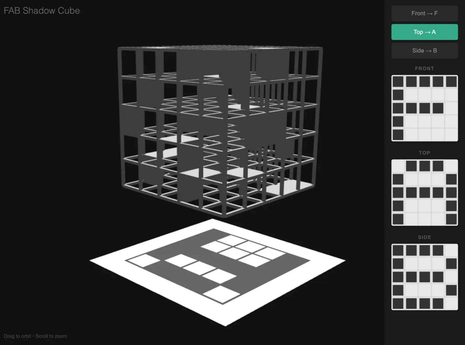
The shadow preview tool, built with Claude. Toggle between three projections, orbit the cube, and see the shadow update in real time.
The FDM Attempt (and Why It Failed)
I tried FDM first, on a Bambu Lab X1 Carbon. It's a fantastic printer, fast, reliable, great print quality, but the geometry of this model is physically impossible for any FDM machine. The lattice has surfaces floating in mid-air on three planes, with nothing beneath them. FDM builds from the bottom up, so the nozzle was extruding into empty space. The result: a messy, stringy approximation of the cube, with collapsed faces and spaghetti where the shadow surfaces should be.
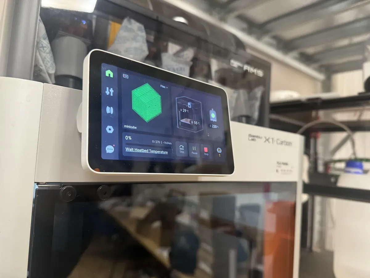
The Bambu Lab X1 Carbon display showing the cube model ("minicube") queued, 0%, waiting for heatbed temperature. Hope was still alive at this point.
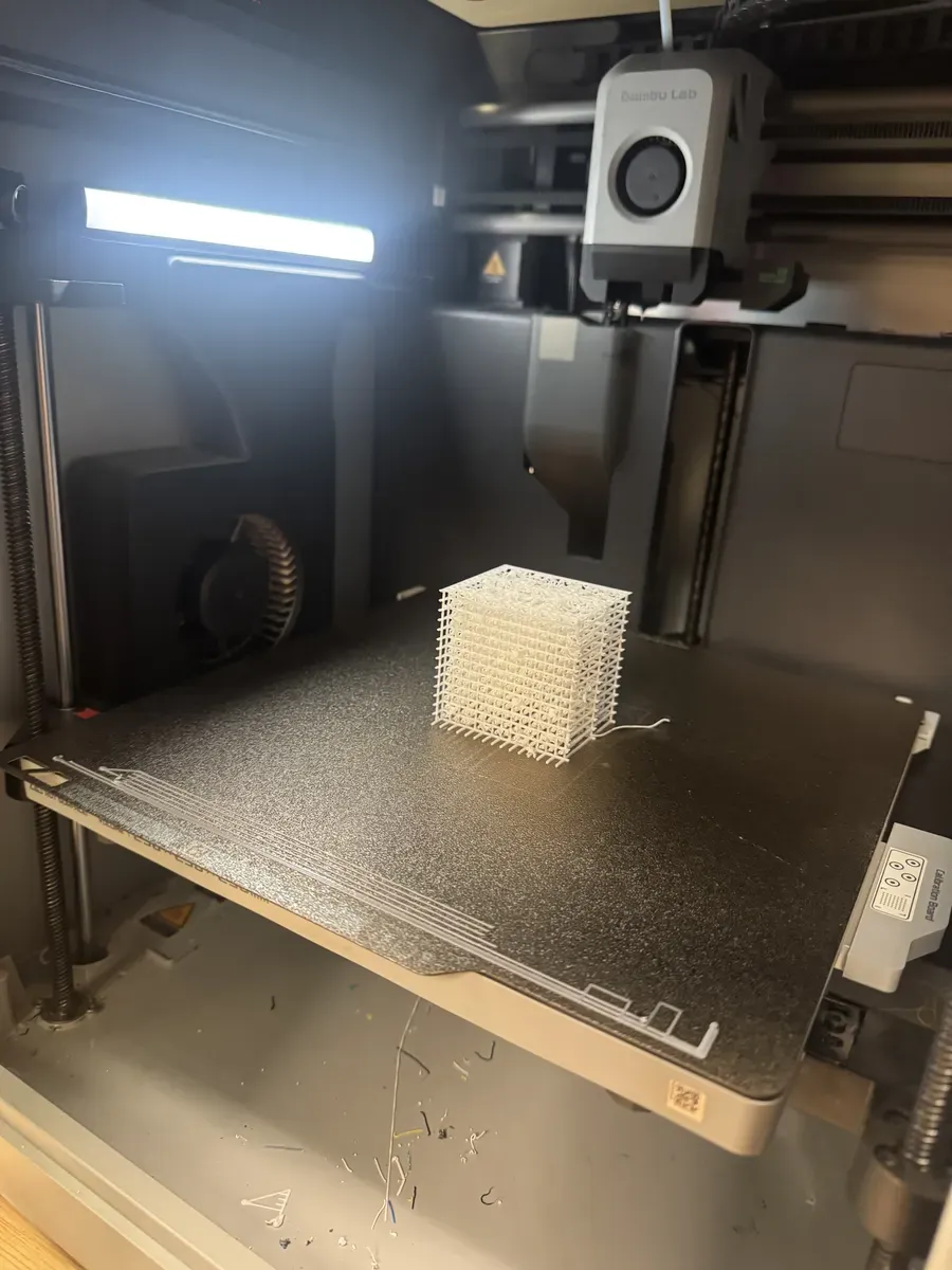
Mid-print: you can already see the stringing where the nozzle tried to print in mid-air
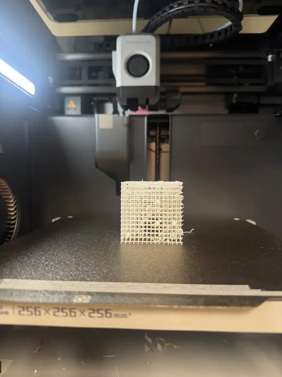
The finished FDM attempt, the grid structure is there, but the floating surfaces collapsed into a stringy mess. This is exactly why the model needed resin.
Slicing in Chitubox
I used Chitubox as the slicer for the ELEGOO Saturn 4. I initially tried angling the model at 45° with auto-generated supports, but both the angle and the supports would damage the lattice geometry. In the end I printed it flat with no supports at all, the lattice structure is self-supporting. The slicer showed 1,554 layers at 0.050mm layer thickness, with an estimated print time of about 4.5 hours.
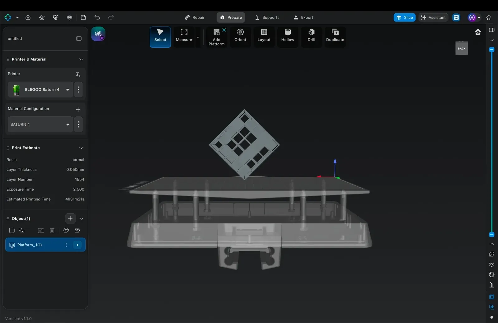
First attempt in Chitubox: the cube angled at 45° on the build platform. This orientation would have damaged the lattice geometry, so I scrapped it.
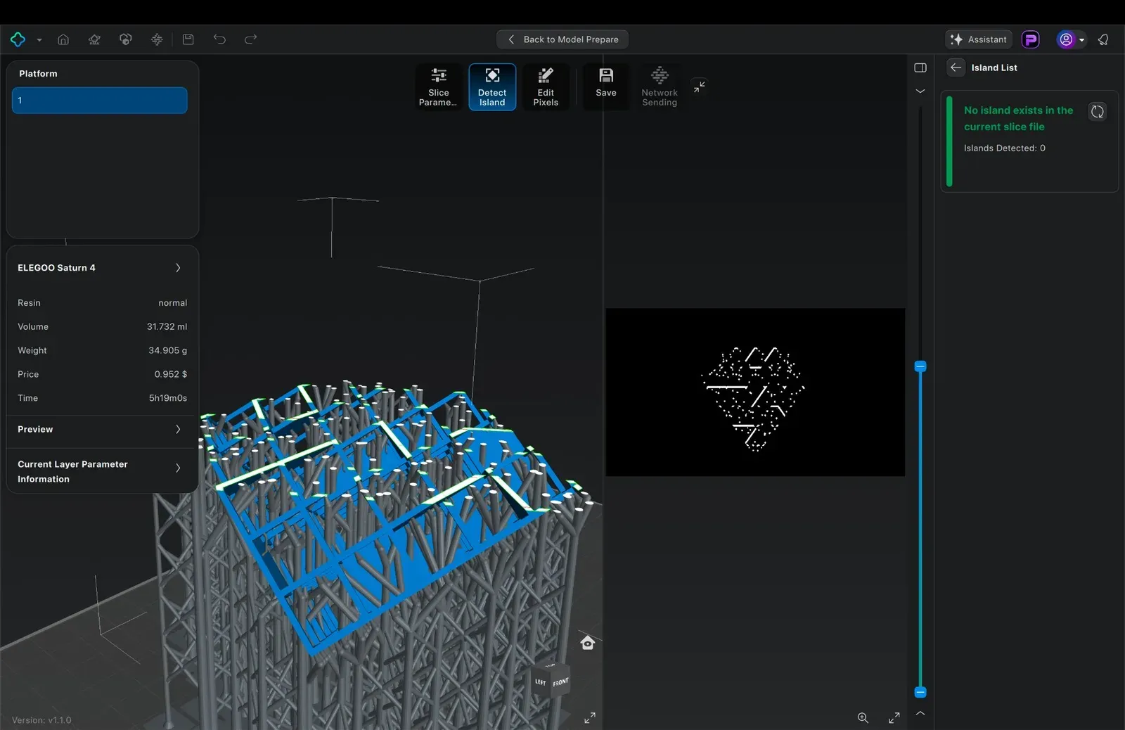
Chitubox auto-generated supports for the angled orientation, but supports would also damage the delicate lattice surfaces. I ended up printing flat, no supports, no angle.
The Resin Printing Process
Resin printing is precise but chaotic. The ELEGOO Saturn 4 uses a 10K mono LCD to cure M3DUSA Titan-Tech 10K black resin layer by layer. The process: pour resin into the vat, load the .goo file via USB, and the printer auto-detects the resin level before starting.
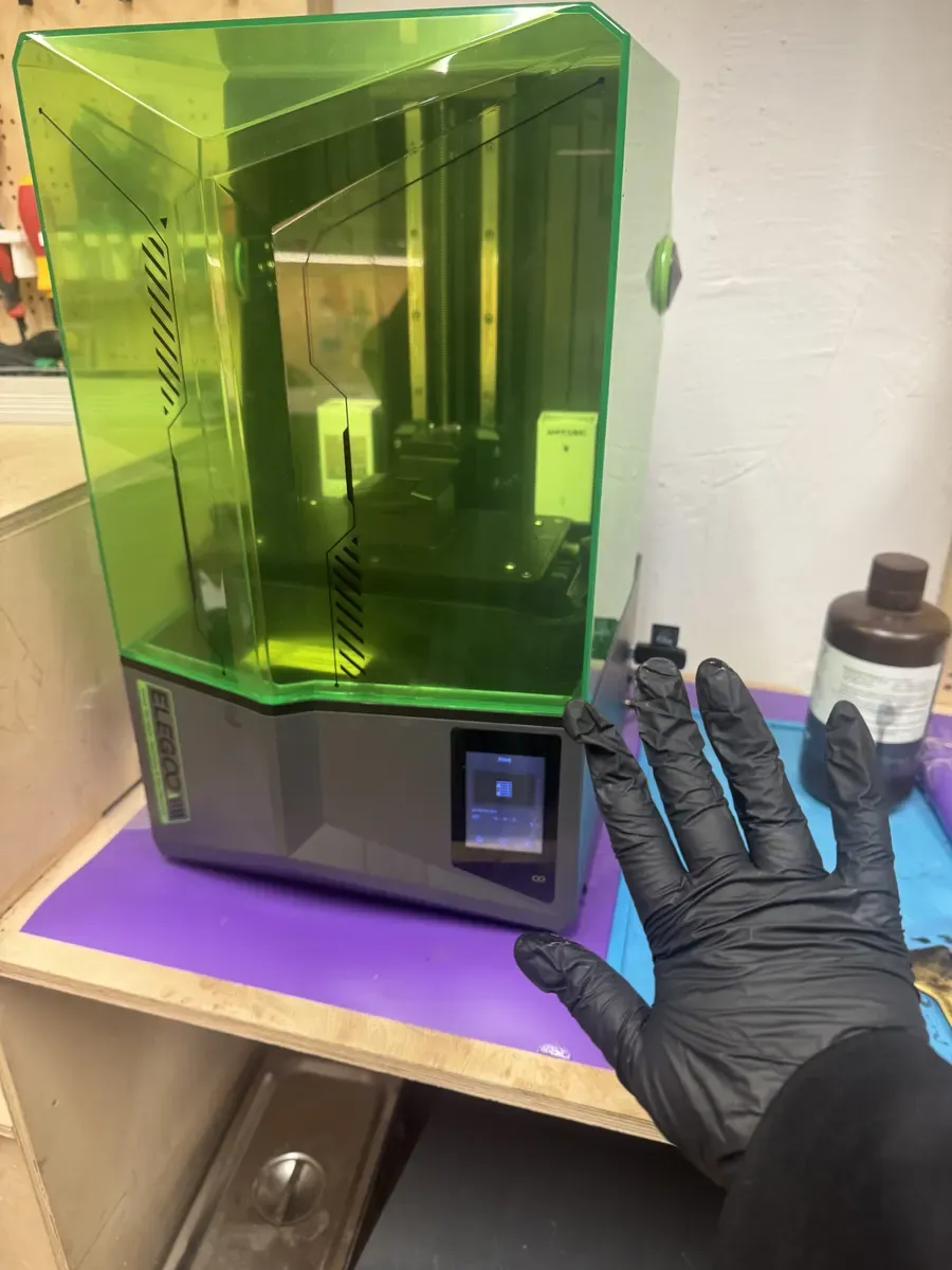
The ELEGOO Saturn 4, green UV-filtering cover protects the resin from ambient light. Always wear nitrile gloves when handling anything near this machine.
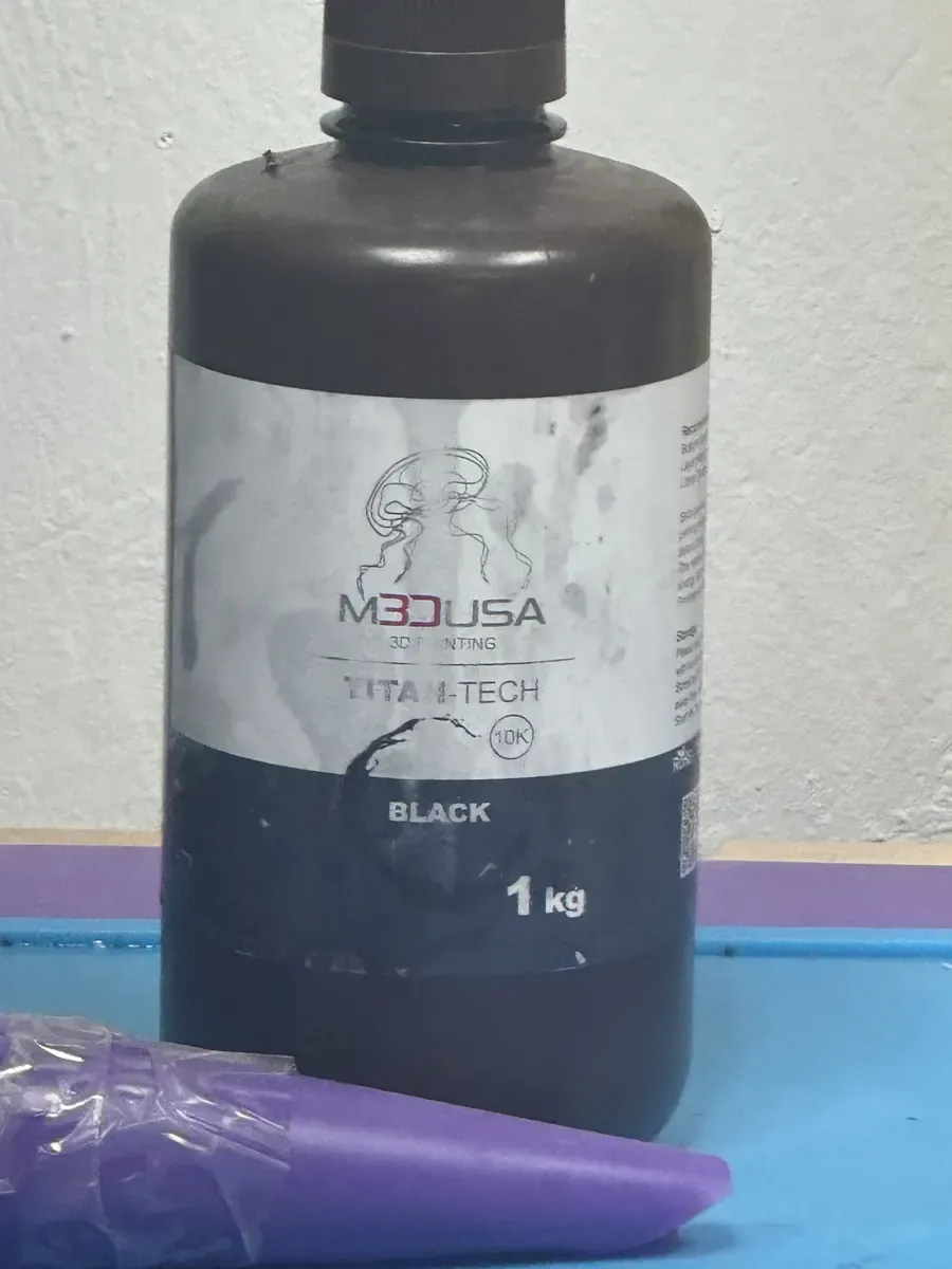
M3DUSA Titan-Tech 10K black resin, 1kg bottle. The "10K" refers to the resolution it's optimised for.
Safety is serious with resin printing. Nitrile gloves only — latex gloves dissolve on contact with resin. Keep it off your skin (it causes irritation). Clean everything with isopropyl alcohol. And the industrial-grade tissue paper roll in the lab? That thing earns its keep.
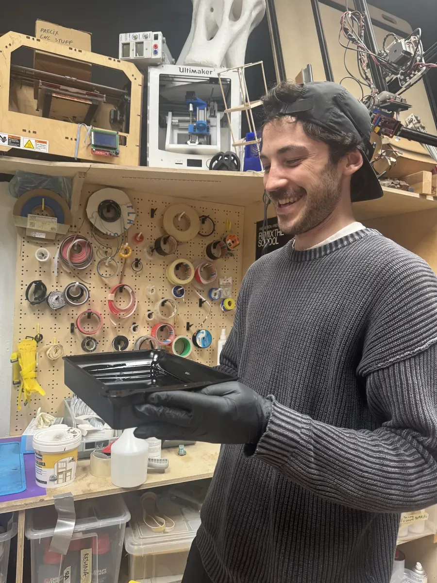
Handling the resin vat, the most dangerous task in the room was handed to a sleep-deprived volunteer. No pressure ;)
Mid-Print and Post-Processing
During the print, you can peek through the UV-filtering window to see the build plate rising out of the resin vat, the model forming upside down. After printing, the model needs an isopropyl alcohol wash to remove uncured resin, followed by a pass in the UV curing machine to fully harden the material.
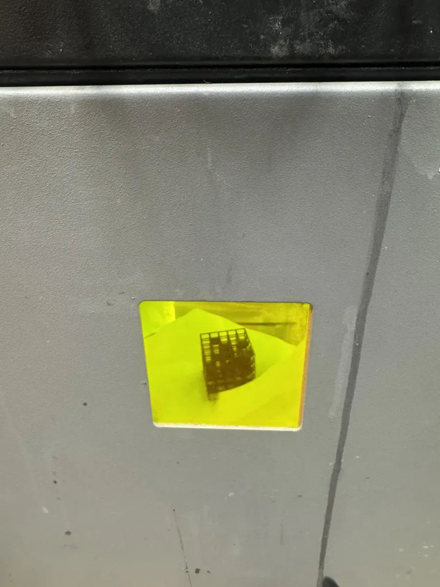
The cube taking shape, visible through the yellow UV-filtering window of the Saturn 4
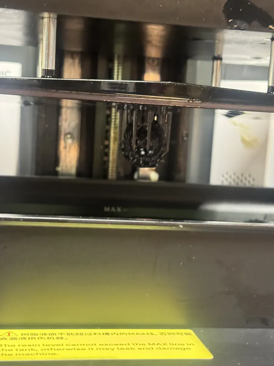
Looking into the printer mid-process: the build plate rising from the resin vat with the cube forming on its underside
The Result
The output was exactly what I was hoping for. The cube looks like an abstract lattice when viewed directly, just a random-seeming grid of surfaces. But hold it up to a light source, and the shadows on the wall spell F, A, B from three different orientations. No supports were needed, no orientation tricks, the geometry just worked.
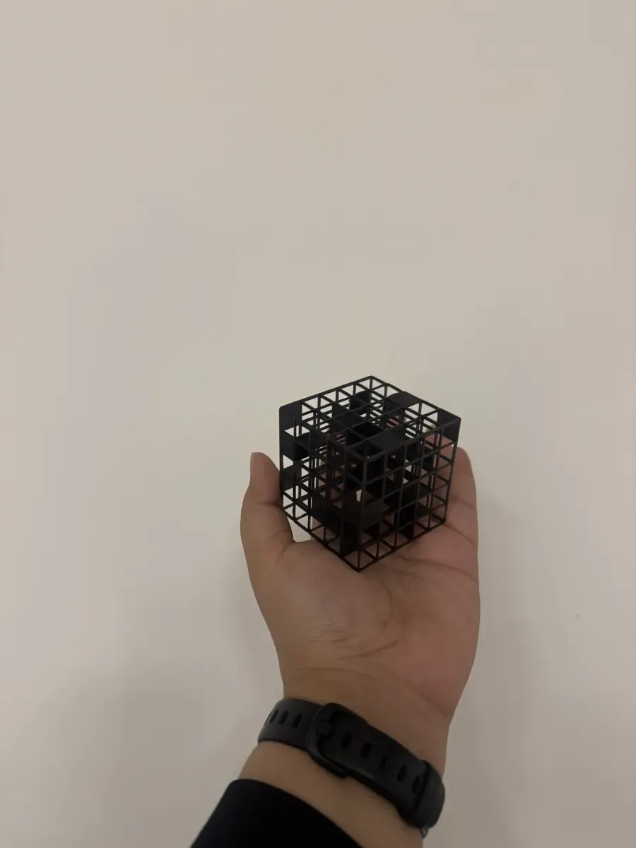
The finished cube, 50mm, black resin, held in hand for scale

The reveal: three angles, three shadows, three letters F, A, B
Group Resin Experiment: Day of the Dead Mask
Before my own print, the class did a group exercise printing a tiny Day of the Dead mask. This was our introduction to handling resin, and it was immediately clear why safety protocols exist. Resin is extraordinarily sticky, gets everywhere, and is genuinely difficult to clean up. The detail on the tiny mask was impressive, though, the kind of fine surface texture that FDM simply cannot achieve.
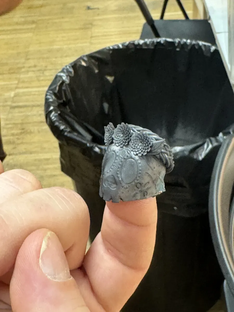
Tiny Day of the Dead mask, printed in resin, smaller than a fingertip, with incredible surface detail
Clay Printing: The Kulhad
The clay printer at Fab Lab Barcelona is unique, it's essentially an Ender FDM printer with all the heating apparatus removed and replaced by a clay cartridge and an air compressor. Think of it as a very precise icing bag: compressed air pushes clay through a 4mm nozzle, and the printer moves in the same GCode toolpaths as any FDM machine. You can print with biomaterials, terracotta, food-safe clay, and experimental pastes.
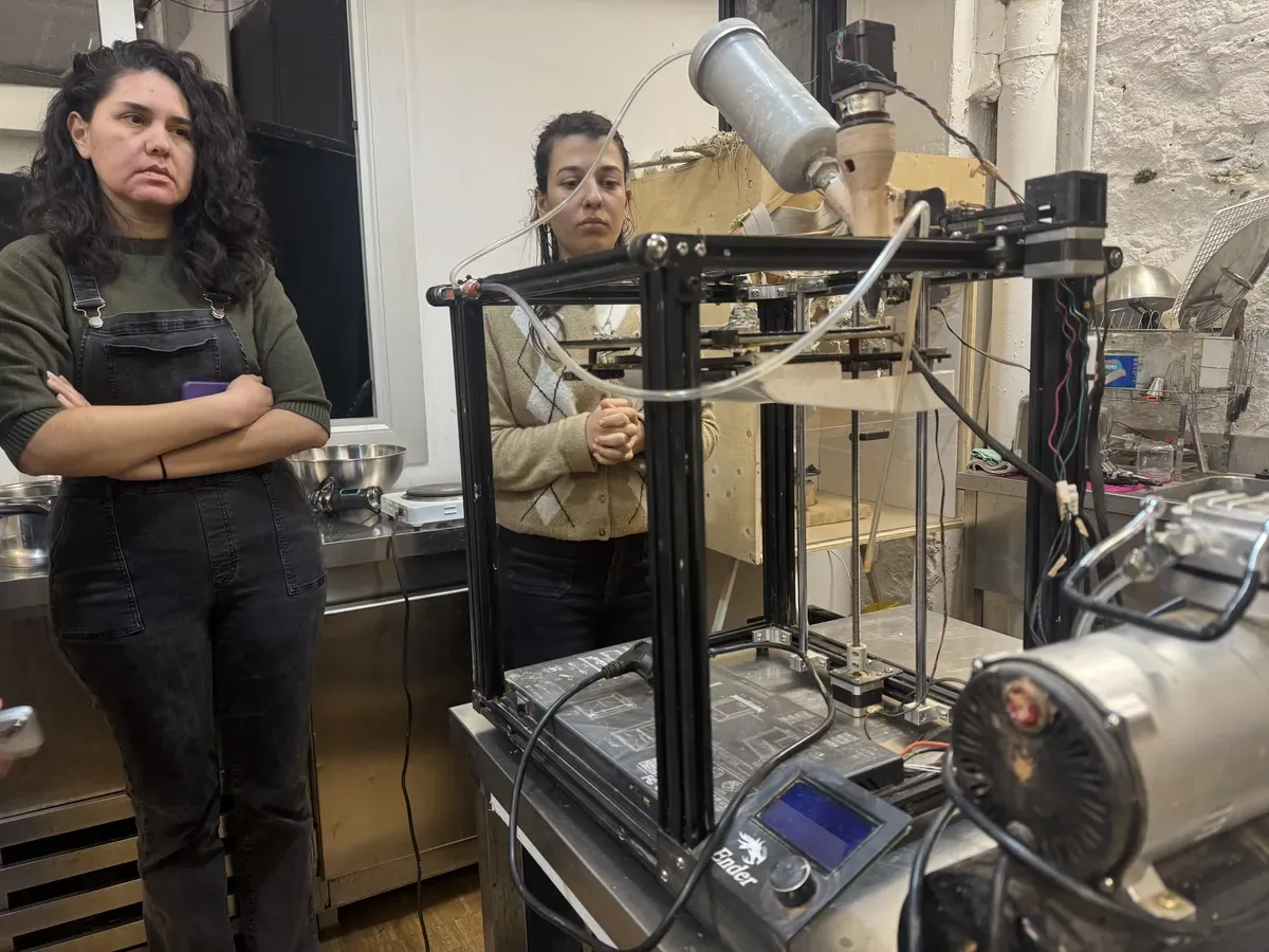
The clay printer: an Ender frame with a clay cartridge on top and an air compressor to the right. A DIY machine with custom Teflon-taped fittings to prevent leaks.
Safety and Setup
The clay printer is more dangerous than it looks. The cartridge is pressurised, if the nozzle gets blocked while the compressor is running, the cartridge can explode. So you have to be mindful: keep listening to the machine, monitor the pressure, make sure both air pressure valves are on, and use a fresh cartridge each time. The compressor has custom-made fittings with Teflon tape to avoid leaks. It's very DIY.
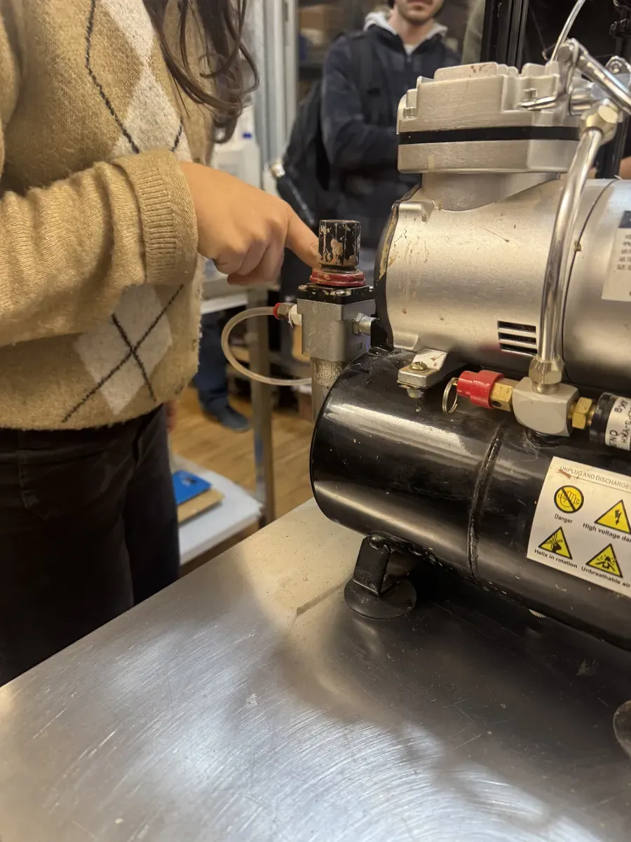
The air compressor: don't overwork it, listen for leaks, and monitor pressure carefully
A key physics trade-off: you either have torque or speed unless you add a gearbox. The clay printer uses this principle, the air pressure provides the force, but print speed must be calibrated against extrusion flow to avoid over- or under-extruding.
Material Notes
We used chamotte clay, which is coarse-grained, not ideal for fine detail, but strong. The paste needs about 5% more water than standard clay modelling consistency. I was surprised by the nozzle's behaviour: 4mm diameter, so you'd expect thin lines, but the extruded material is actually quite wide once deposited. Otherwise the layers collapse onto themselves. Clay shrinks when it dries, you can calculate the shrinkage factor by measuring before and after drying.
The Demo Print and the Kulhad Plan
The class demo was a simple cylinder, nothing fancy, just a test of the pipeline. But it revealed something interesting: the printed cylinder had small bumps and ridges that weren't in the design. We figured out that these happen when the air compressor pauses between pressure cycles, the nozzle stops extruding for a moment, but the printer head keeps moving, then the pressure resumes and deposits a small blob. It's a machine artefact, not a design flaw.
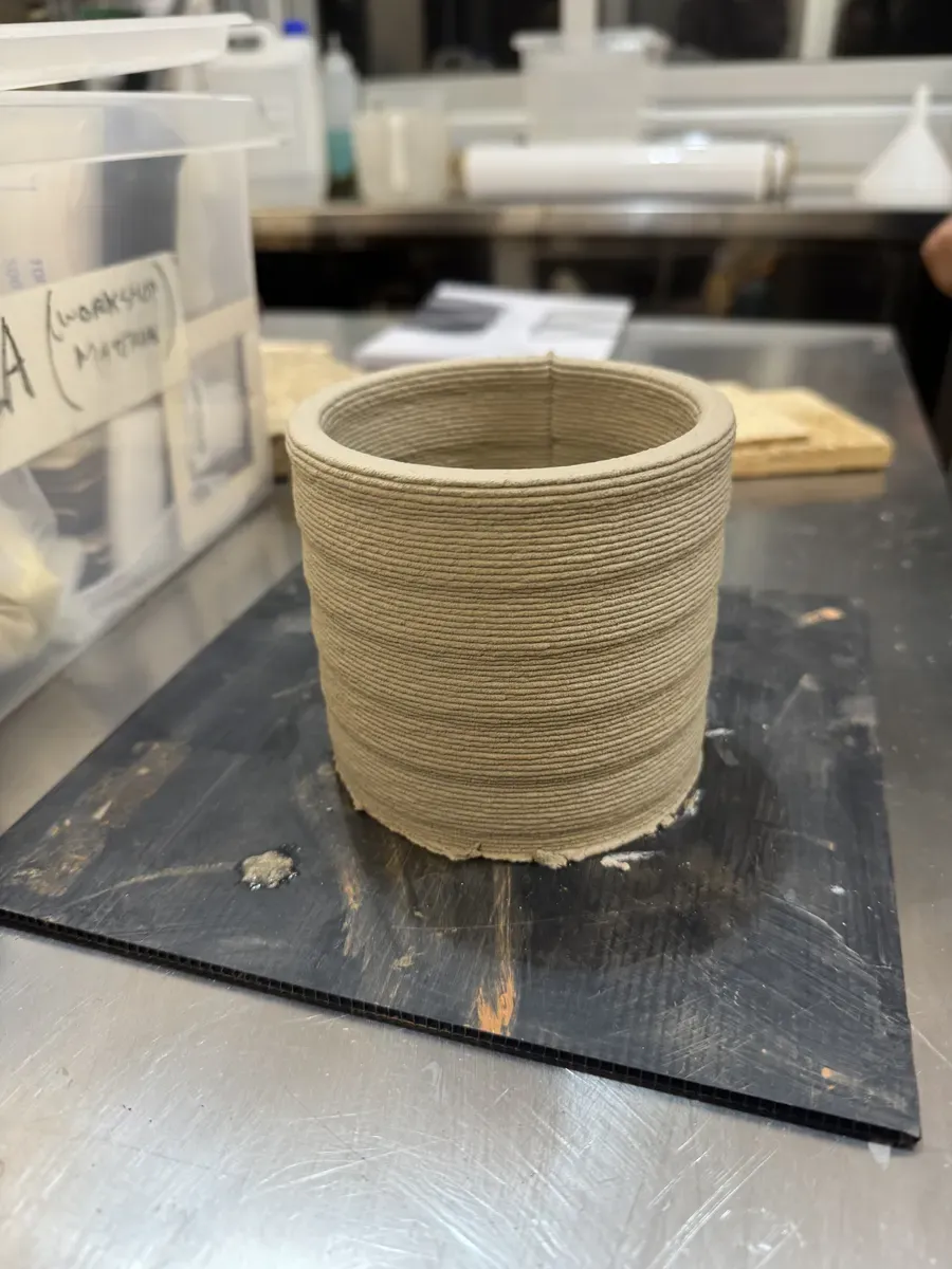
The demo cylinder, layer lines give it a ribbed texture. Notice the small bumps from air compressor pressure pauses.
My goal is to print a kulhad — the small terracotta cup used for chai across India. They're traditionally hand-thrown on a wheel, disposable, and compostable. Printing one in clay felt like a nice bridge between digital fabrication and traditional craft. I modelled a simplified version in Rhino — a cylinder with a radius of 50mm, then fed it into the Grasshopper pipeline to generate GCode. I also tried a more ornate version, but it was too complex for the clay printer and had to be removed.
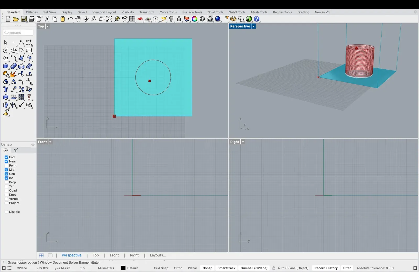
The kulhad model in Rhino: top, perspective, front, and right views. Simple cylindrical geometry, ready for the Grasshopper GCode pipeline. Print is next.
The Grasshopper-to-GCode Pipeline
The clay printer doesn't use a traditional slicer like Cura or PrusaSlicer. Instead, the toolpath is generated entirely in Grasshopper (the visual programming environment inside Rhino). Fab Lab Barcelona has a custom Grasshopper definition that takes your geometry and produces GCode with full control over every parameter.
We installed several Grasshopper package managers to extend Rhino's capabilities: Heteroptera, Human, and Pufferfish, each adding specific node types for mesh operations, data handling, and geometric transformations.
Pipeline Overview
The definition has three main stages: geometry input, slicing configuration, and GCode generation. The geometry (a Brep or Mesh from Rhino) gets centred, sliced at a configurable distance, and converted into movement coordinates.
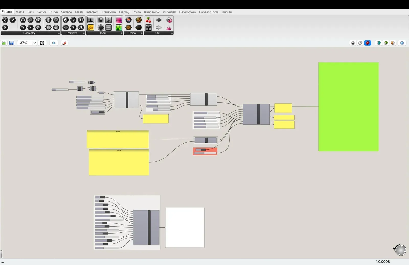
The full Grasshopper definition, geometry flows left to right, from input parameters through clusters to the final GCode output
Geometry and Slicing Cluster
The first cluster takes your geometry and printer dimensions as input. Key parameters: the Cartesian printer bed is 220×220mm with 300mm Z height. Slicing distance is 2.0mm, nozzle diameter 4.0mm, Z bed height offset 1.0mm, and tolerance/resolution at 0.20. The output confirms: "No errors, you are good to go. Your print is a Brep and a Mesh. Print size X100mm Y100mm Z100mm."
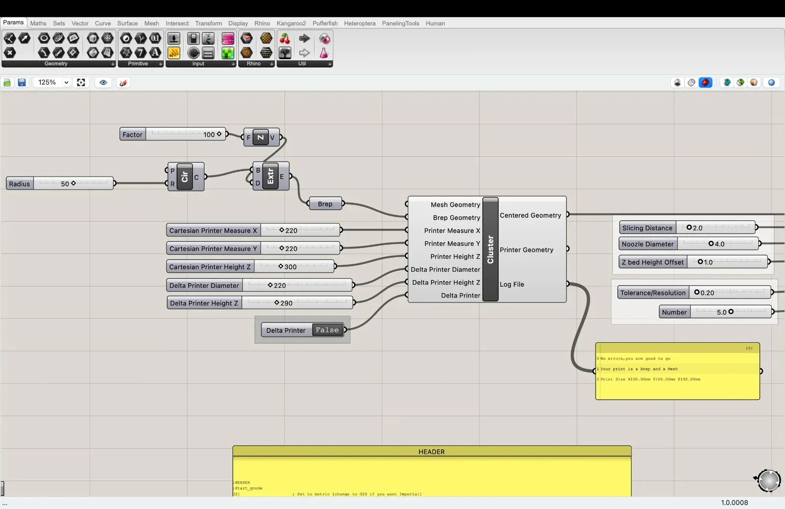
Geometry input cluster: printer dimensions, slicing distance, nozzle diameter, and the validation output confirming the model is print-ready
GCode Generation
The second cluster handles the actual GCode generation. The key settings: jog speed 4000 mm/s, print speed 1000 mm/s, extrusion multiplier 15.00, and a z-hop safety offset of 5.0mm. The output is the total print length (15,704mm), volume (0.12 litres), and estimated time (~19 minutes). The Kossel Clay Printing configuration adds custom start and end GCode blocks.
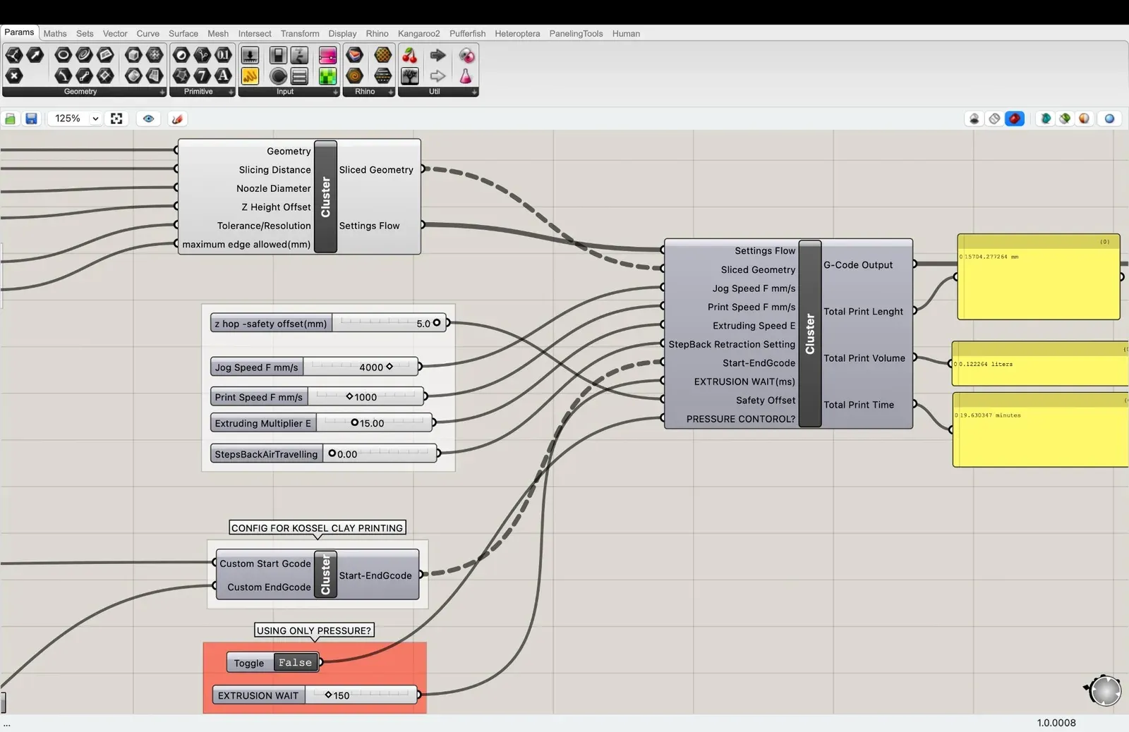
GCode generation cluster: speed settings, extrusion multiplier, and the output showing total print length, volume, and time
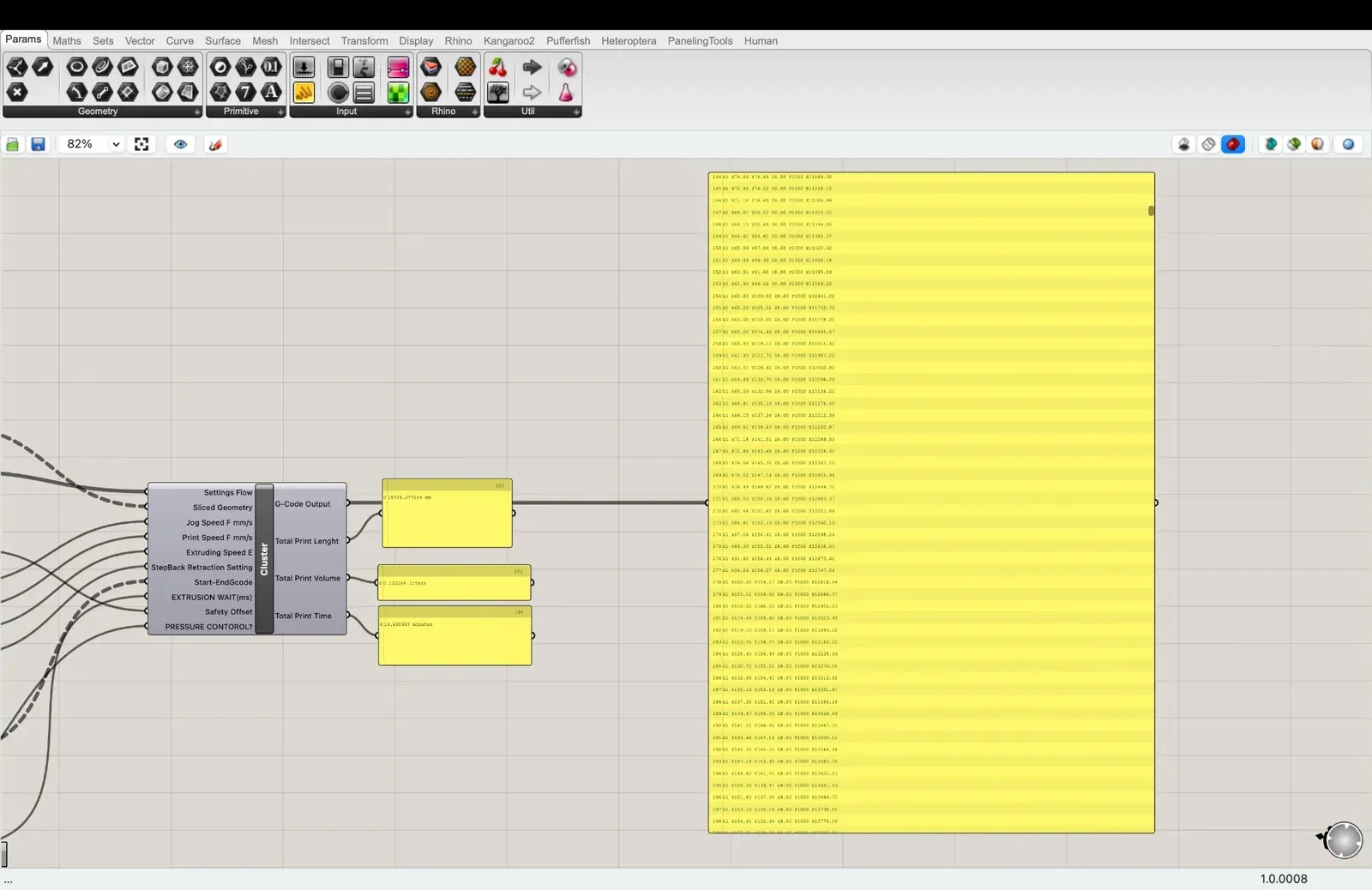
The raw GCode output, hundreds of coordinate lines (G0/G1 movements) ready to send to the printer
GCode Structure
The GCode follows a standard structure: Header (set metric units, absolute coordinates, home position), Toolpath (the actual print movements: G0 for rapid positioning, G1 for controlled extrusion), and Footer (relative positioning, turn off layer fan, return to home). The optional configuration cluster controls heated bed temperature (60°C), extruder temperature (230°C), cooling fan, and motor behaviour.
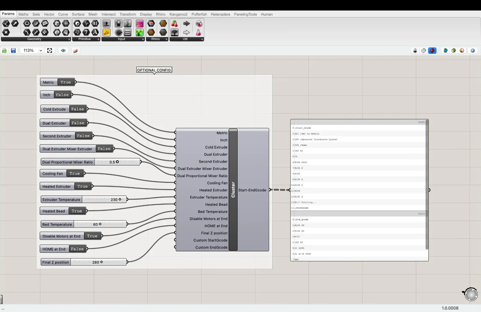
Optional configuration: metric units, cooling fan, heated extruder at 230°C, heated bed at 60°C, and the generated Start/End GCode blocks
Group Assignment: Testing Our Printer's Design Rules
The group assignment was to test the design rules for our 3D printer. As a group we ran a capability test on the Bambu Lab X1-Carbon in PLA, a single print bundling infill patterns, surface textures, a bridging test, an overhang arc, and a Benchy. The full results and machine settings are on the group work page (linked in the sidebar).
What I took away, and used the same week: the X1-Carbon bridges cleanly up to 40mm with no sag, and overhangs stay clean only up to 45° before the nozzle starts bumping the column. That 45° wall is exactly why my FAB shadow cube, with surfaces floating in mid-air on three planes, was never going to survive on FDM, and why I moved it to resin. Knowing the printer's floor before designing saved me from guessing. One more lesson from a mid-print filament runout: feed new filament generously, the machine pulls more than you expect before it takes over.
For Maya's Mirror
This week I pushed Maya's Mirror forward on three fronts: mapping the media pipeline for variation 1 (the face-tracking botanical transformation), attempting to host the experience directly on the Barduino ESP32-S3, and experimenting with generating text on 3D model UV surfaces, research for phase 3 of the project.
Variation 1: MediaPipe Face Mesh
I built a working version of the core mirror experience, a webcam feed that uses MediaPipe face tracking to detect facial landmarks and warp the live image in real time. The current prototype smoothly distorts the viewer's reflection, laying the groundwork for the botanical transformation layer that will come next.
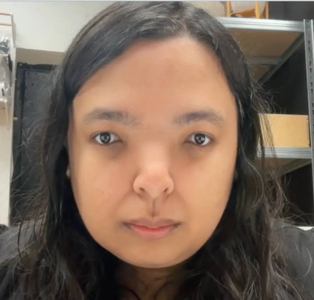
Face mesh tracking in action, using MediaPipe to manipulate and move face elements like distance of eyes and length of nose.

This is what I usually look like.
Hosting on the Barduino (Failed)
I tried to host the mirror experience directly on the Barduino ESP32-S3 as a local web server. I got as far as serving a basic "hello from barduino" page on the local network (172.16.21.68), but the ESP32 doesn't have the processing power or memory to run MediaPipe and serve a webcam-based experience. This needs a much better setup, likely a Raspberry Pi or a dedicated laptop running the mirror software, with the Barduino handling sensors and physical interaction only.

"hello from barduino", proof the ESP32 can serve web pages, but nowhere near enough for a real-time face-tracking mirror
3D UV Surface Text (Phase 3 Research)
For phase 3 of Maya's Mirror, I want to generate botanical patterns on 3D surfaces. To learn the technique, I experimented with writing text onto a 3D model's UV surface, specifically, the word "CAT" mapped onto a cat model. The text wraps around the geometry following the UV unwrap, which teaches me how generated patterns (eventually flowers and botanicals) can be projected onto arbitrary 3D forms.
Screen recording of the cat UV experiment — the word "CAT" wrapping around the 3D model's UV surface in real time
Failures and Glitches
Not everything worked. Early iterations of the face-tracking pipeline produced glitchy, fragmented outputs, face regions duplicated and offset, creating unsettling collage effects. These failures were actually useful: they showed me where the face mesh detection breaks down and how the warping algorithm handles edge cases.

A gloriously broken iteration, face regions duplicated and misaligned, creating an accidental cubist portrait