
a modular light sculpture of color combination
.gif)
This work is licensed under a Creative Commons Attribution-NonCommercial-ShareAlike 4.0 International License.
d e s i g n
from My Cyan CiTies art project
From this drawings I make about cities I took a character as a TREE. I wanted to make an sculpture and since week 3 I took this character and try to make a parametric construction kit with the branches of this TREE and some petals as flowers.
week 3 "imaginary tree"
After that model I got the idea to make the sculpture as this TREE but combined the petals wit some RGB leds I could control by color mixing and programming.
After Output devices week I decided to make the sculpture with changing colors as I connect some petals as input.
I got the concept idea in the following weeks that you can see the progress here
4 changing colors after week 10.
In this week I tried the RGB LED and some coding to find the color combinations i liked the most. This colors where the base for the final code of the 16 color combinations:
| RGB | PINK | BLUE | PURPLE |
|---|---|---|---|
| Red | 0 | 200 | 150 |
| Blue | 0 | 0 | 50 |
| Green | 200 | 255 | 255 |
s y s t e m I n t e g r a t i o n
to the sculpture design
After making the final model of the sculpture and decide the pieces I had to define the system integration of all the fabrication processes and materials:
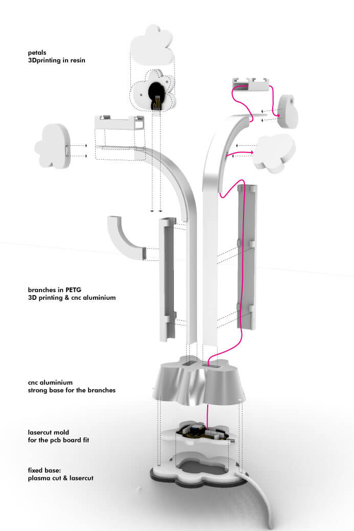
final system integration design
and p i e c e s
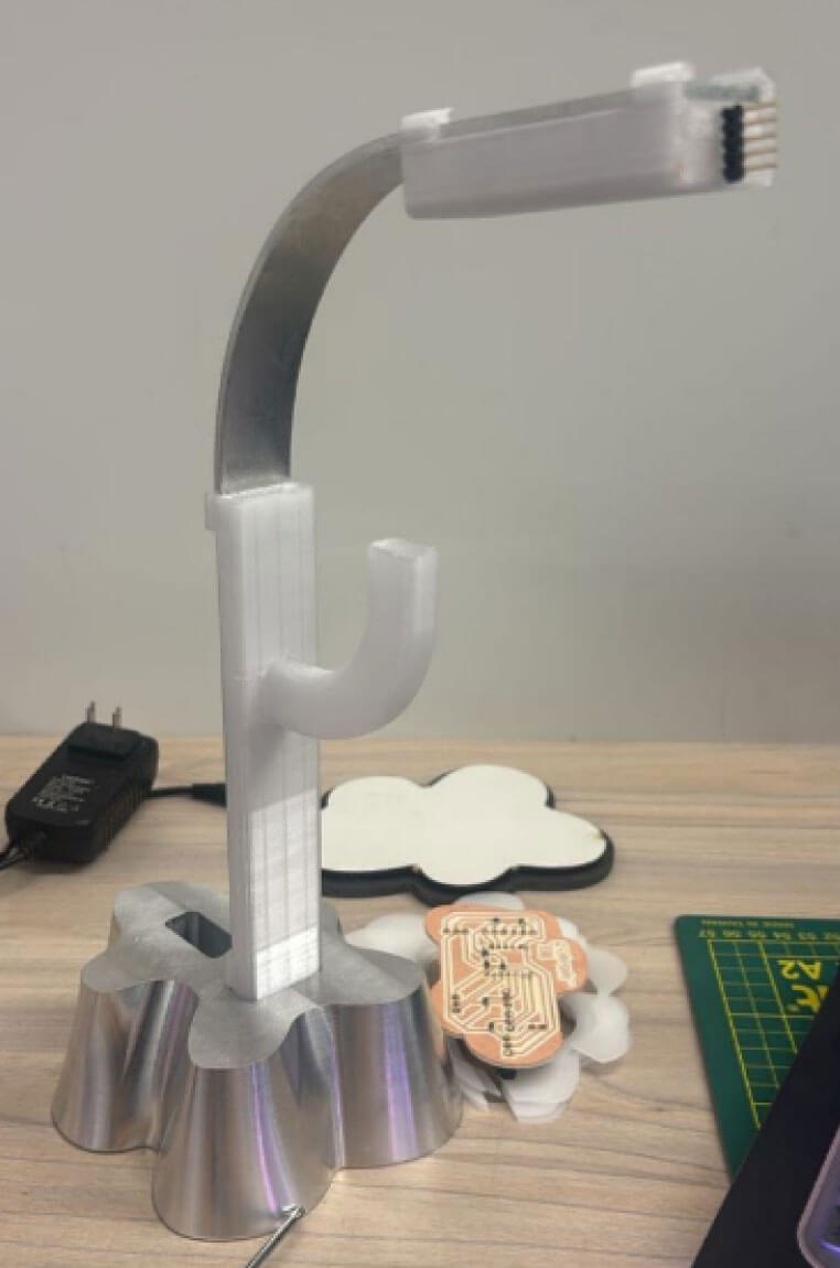
The system integration of the project will include 3D printing, cnc in aluminium, lasercut, rgb led output, button signal input, electronics and programming. I divided everything in 8 pieces and 2 materials basically appart from the components of the electronics design. Check each piece in detail above:
The project was conceived as a sculpture. After the Wildcard Week, where I had to make a metal CNC, I was delighted to think of a metallic sculpture that was transparent at the same time.
The metal would help give it the necessary rigidity, but one side had to remain translucent to reflect light. That is why the rest of the pieces were 3d printed in PETG to give it more resistance than in PLA and others in transparent resin for the light effect that I could explore in week 10.
e l e c t r o n i c s D e s i g n
I basically have 2 electronics designs to make: The general pcb board that connects everything and the separate boards for each petal to connect.
Base pcb board
petals pcb board
base pcb board
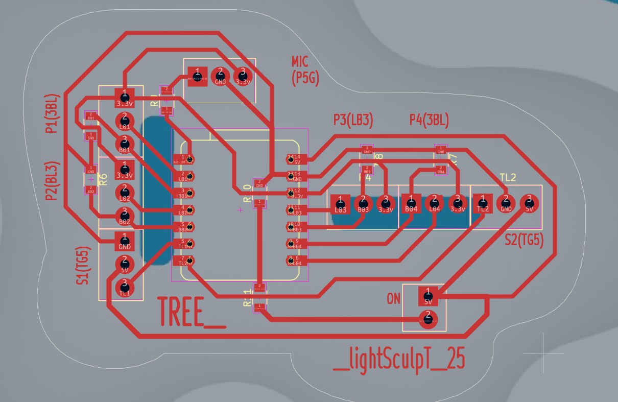
The pcb board for the base has the XIAO ESP32C3 microcontroller and two separated parts. The connections for the petals and the ones for the led stripes. The petals needs to be in pull down and have each a free pin and a 3.3v for the input signal. So 8 pins of the XIAO SP32C3 will go for the petals.
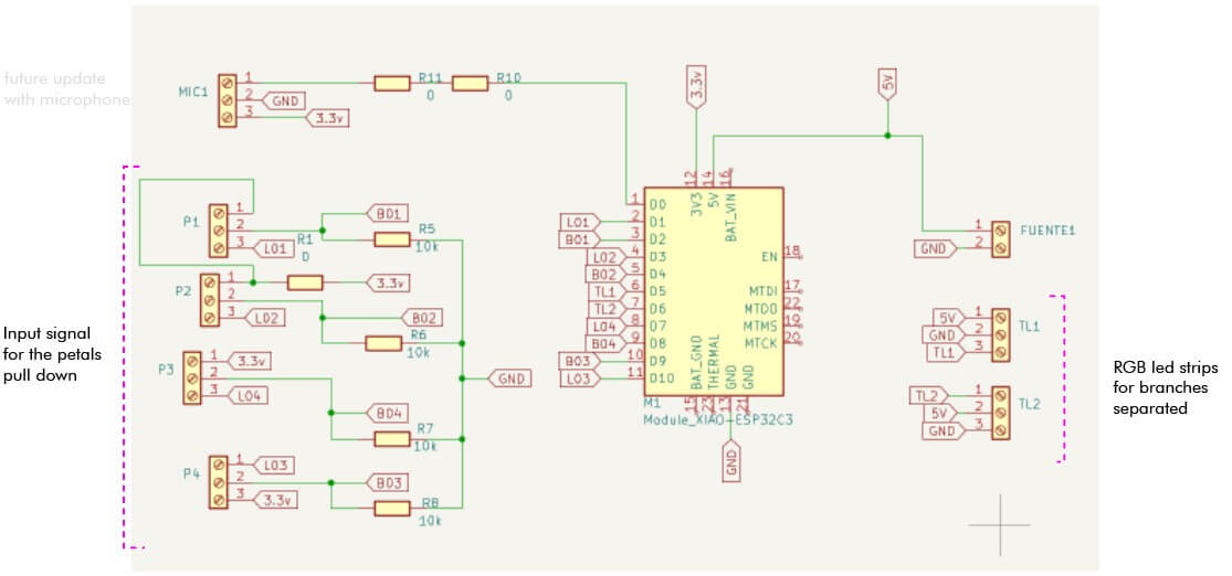
Schematic design
The pcb board for the base has the XIAO ESP32C3 microcontroller and two separated parts. The connections for the petals and the ones for the led stripes. The petals needs to be in pull down and have each a free pin and a 3.3v for the input signal. So 8 pins of the XIAO SP32C3 will go for the petals.
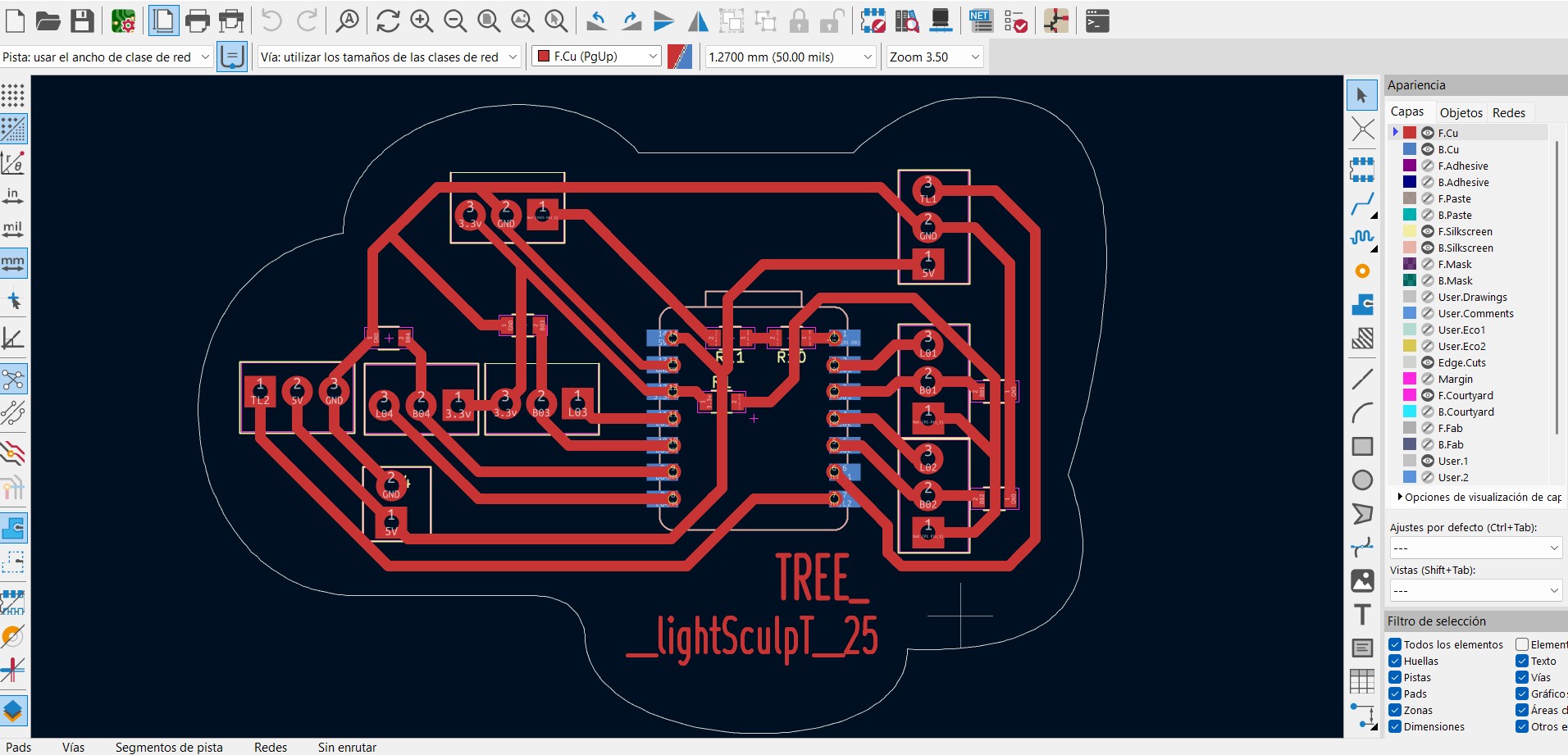
final pcb board
In the design stage I didn’t consider at first it would be a through-hole PCB board. I just fitted it into the footprint of the base and did not consider it would be upside down and actually not fit. I had to move everything because a simple mirror will not work in this footprint.
Base pcb board
petals pcb board
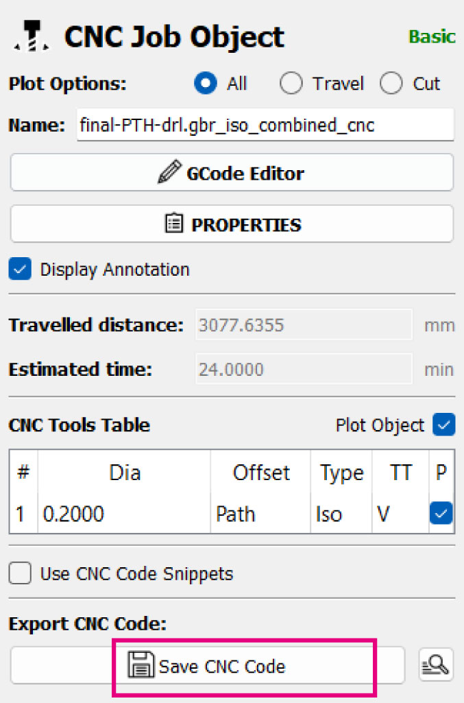
To fabricate the board I also had to export the files for the cut trough holes in Kicad with an apart option I almost missed.
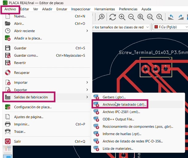
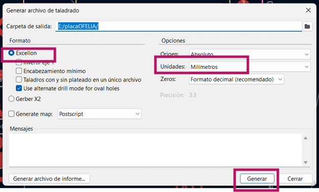
And exported in Flatcam to separate the circuit from the cut trough holes files.
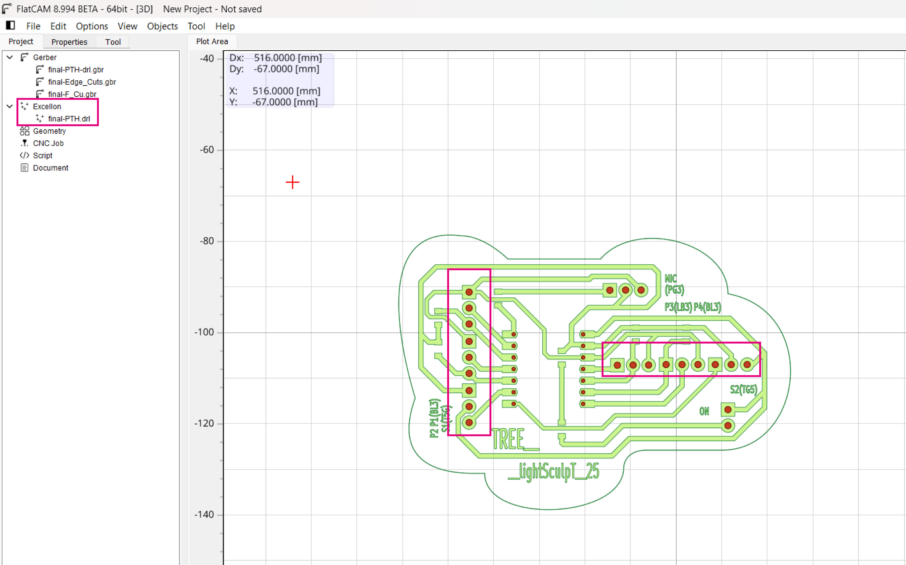
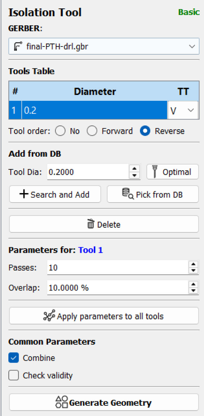
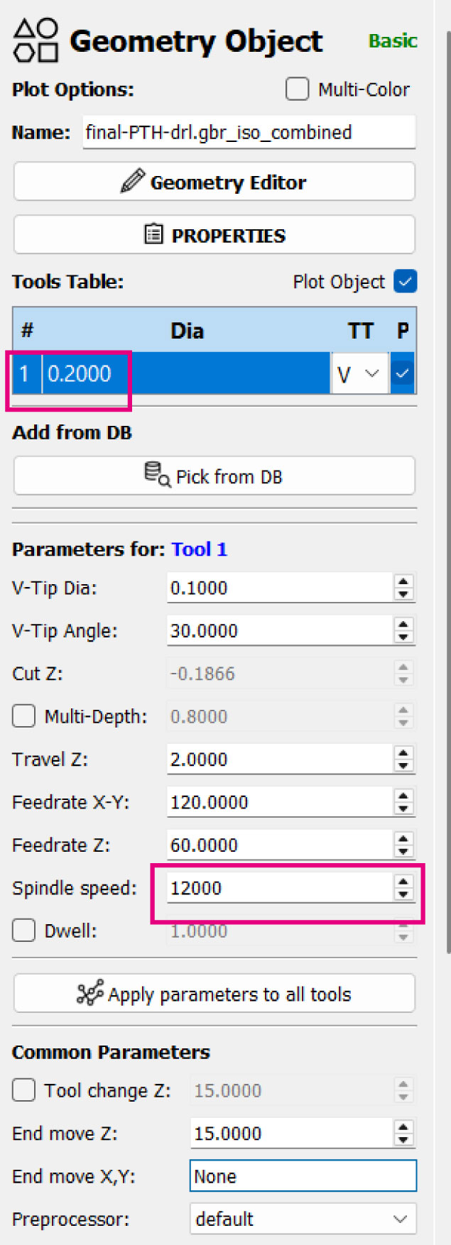
Flatcam g code generator
PetaLs pcb board
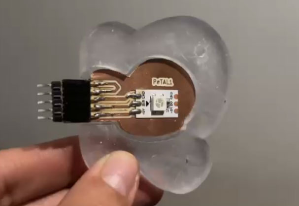
For the petals was an extra challenge. Since I will use a RGB led from a led strip I had to clear the board in that part. Also as I will connect this with another board I has to just connect a pin socket to the led strip.
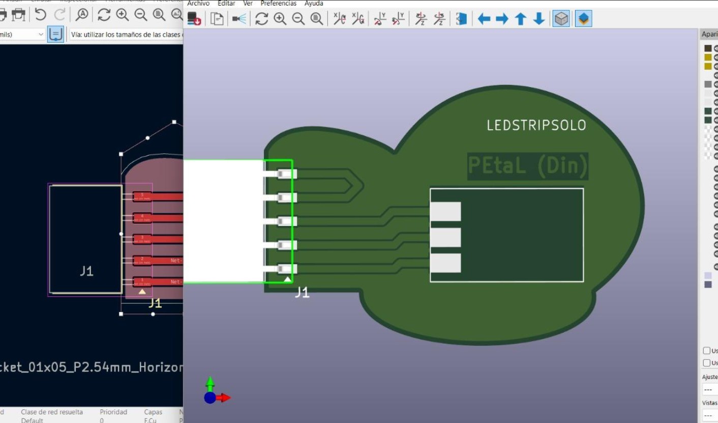
KiCad 3d view
f a b r i c a t i o n
I got several fabrication processes. Starting from the base to the top petals I will explained all the stages of the fabrication. From the design to setting machines to the assembly.
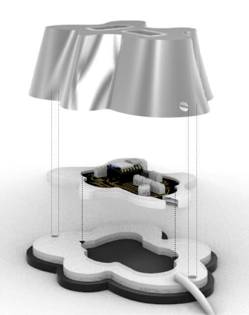
1. base lasercut + cnc aluminium + pcb board
b a s e L a s e r c u t
For this week I tried a new lasercut machine from a new lab in Universidad de Lima for the faculty of architecture. It is a Trotec Q500 series which works with its own software called Trotec Engraver.
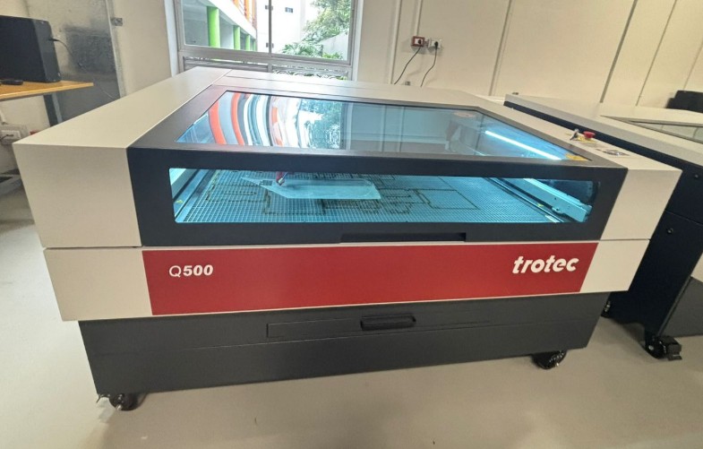
laser cut machine
I exported my dxf design and opened in AutoCAD, where I had to select the software and maintain the default paper size of the machine. It is iportant to chang the scale to 1:1 so the drawing can fit in the real size of the machine.
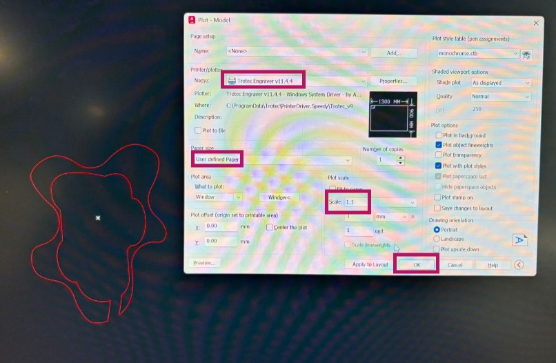
autocad print settings
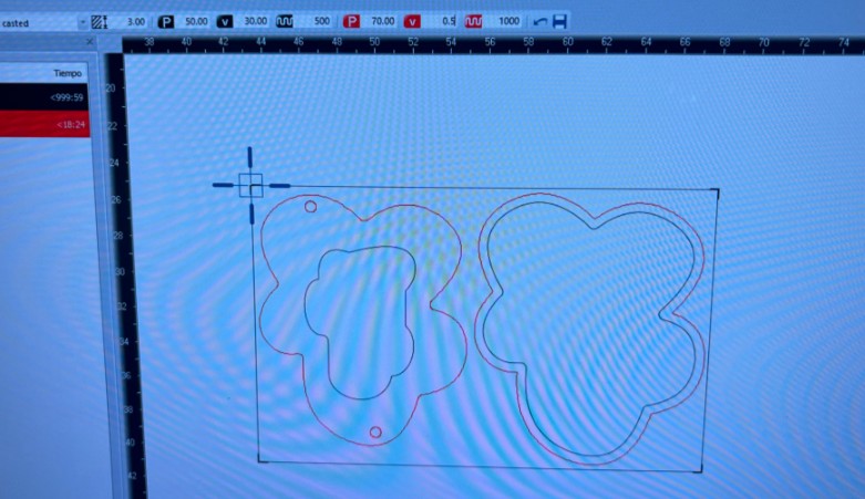
Trotec software
The settings for 4mm transparent acrlylic are:
| power | speed | frequency | |
|---|---|---|---|
| raster | 50 | 30 | 500 |
| cut | 70 | 0.5 | 1000 |
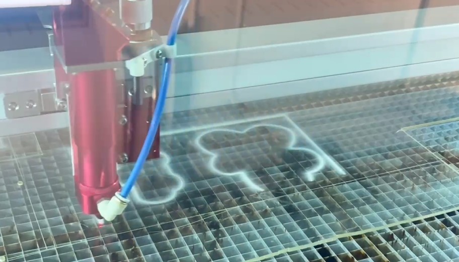
process
c n c A l u m i n i u m
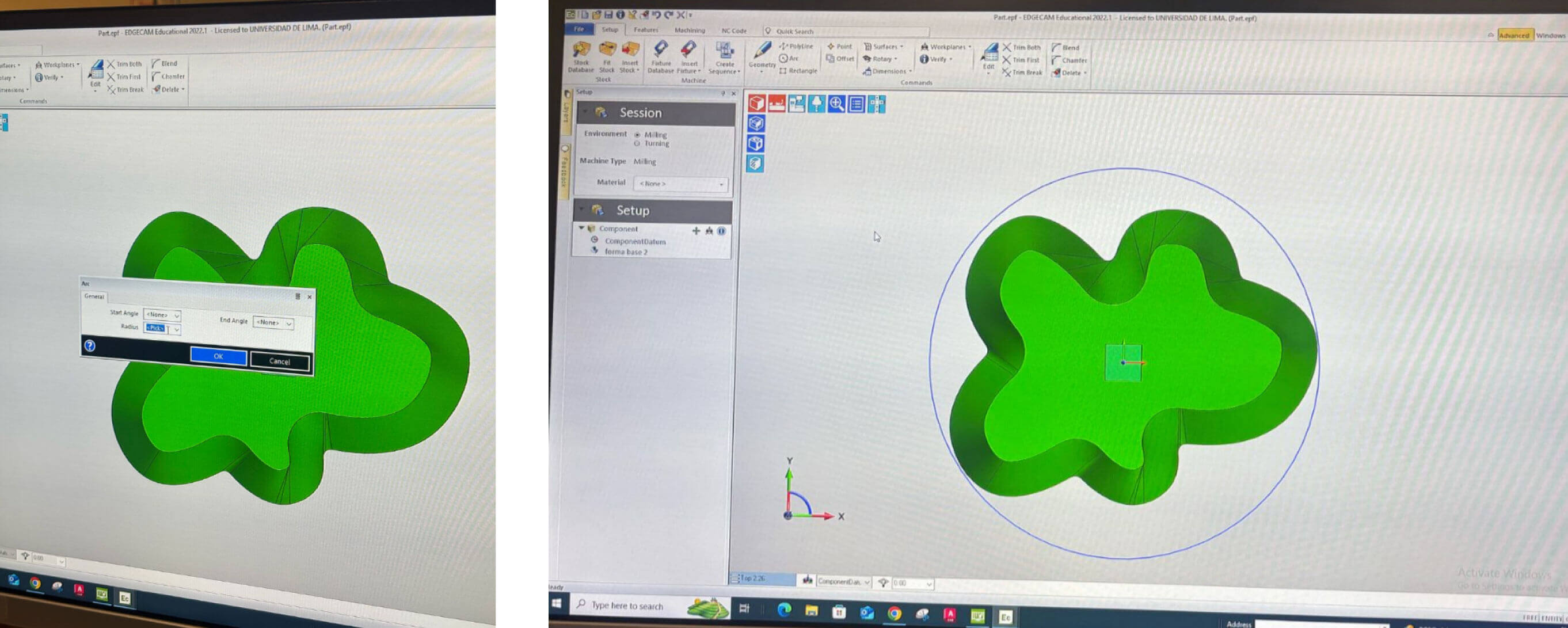
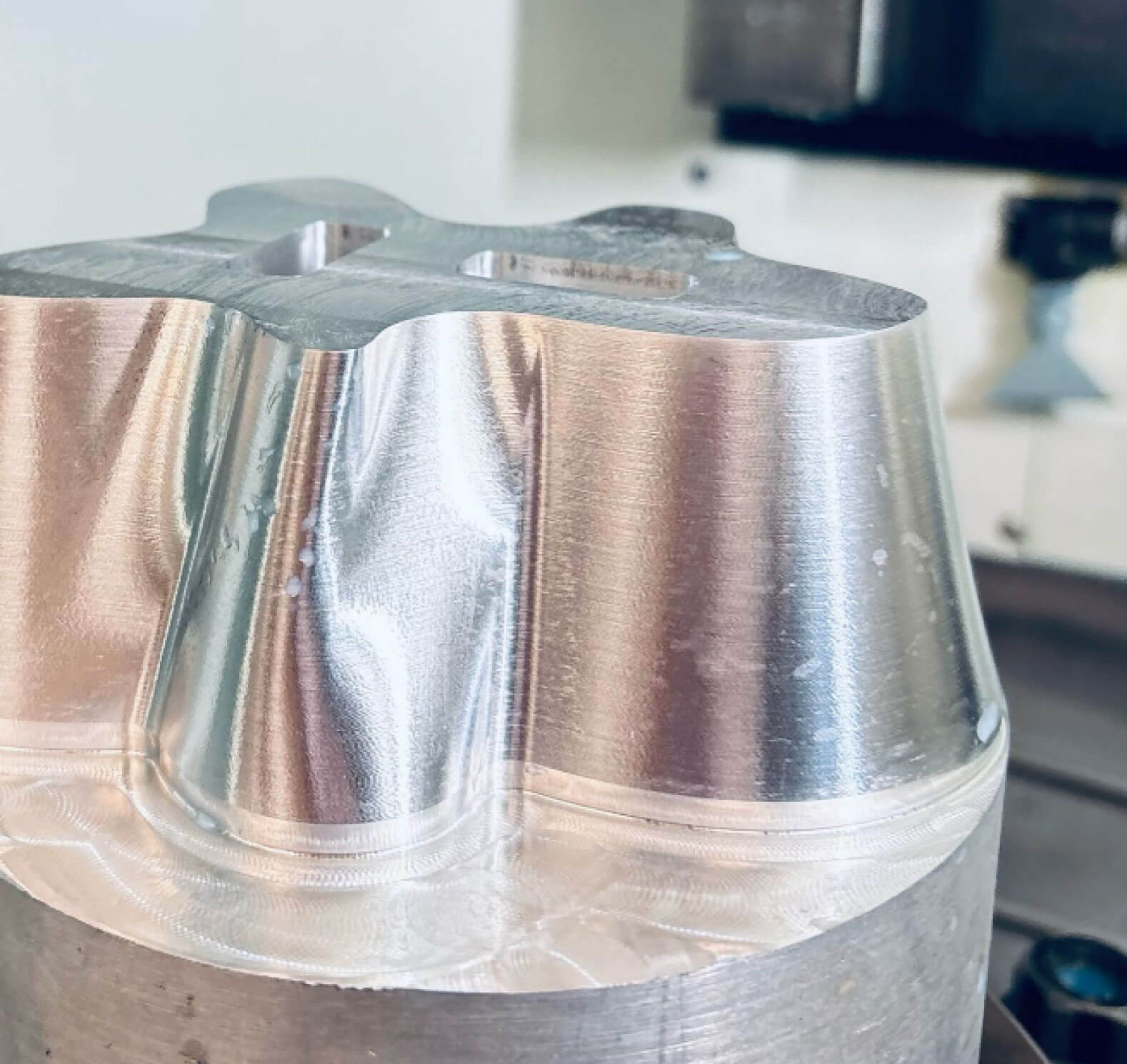
I made the base on Wildcard Week with the Kitamura Mycenter 3XG 5-axis CNC mill from the Fab Lab Universidad de Lima. They gave me a block of aluminium of 150mm of diameter in which I had to fit my base design. Happily it had 130mm of diameter so it fit perfectly.
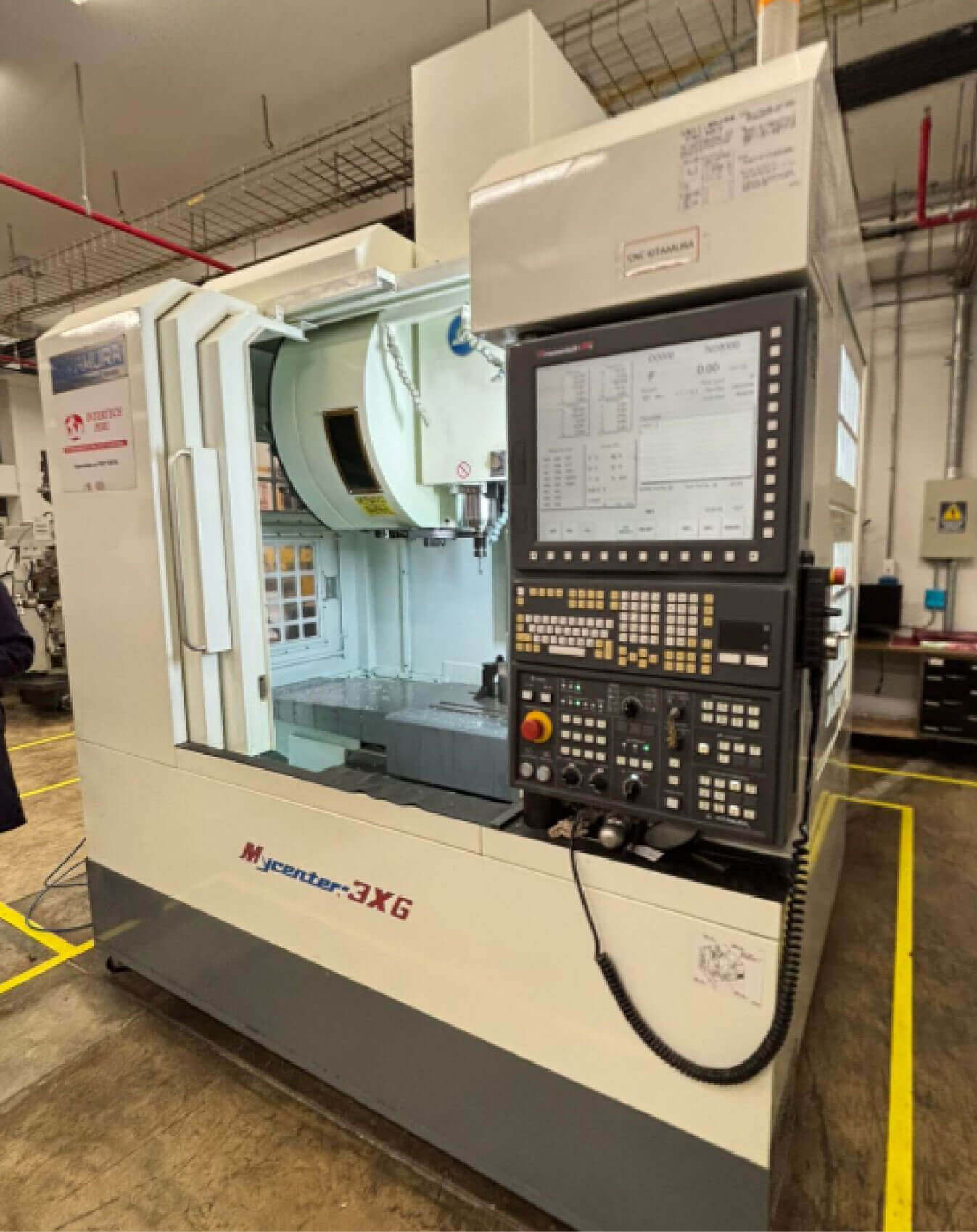
Kitamura machine

aluminium base material
It is explained in detail every parameter and settings from the files in Week 16 page. First I make just the exterior milling and then I had to turn the base over to be able to make the holes inside.
some settings for the exterior milling


process
p c b B o a r d
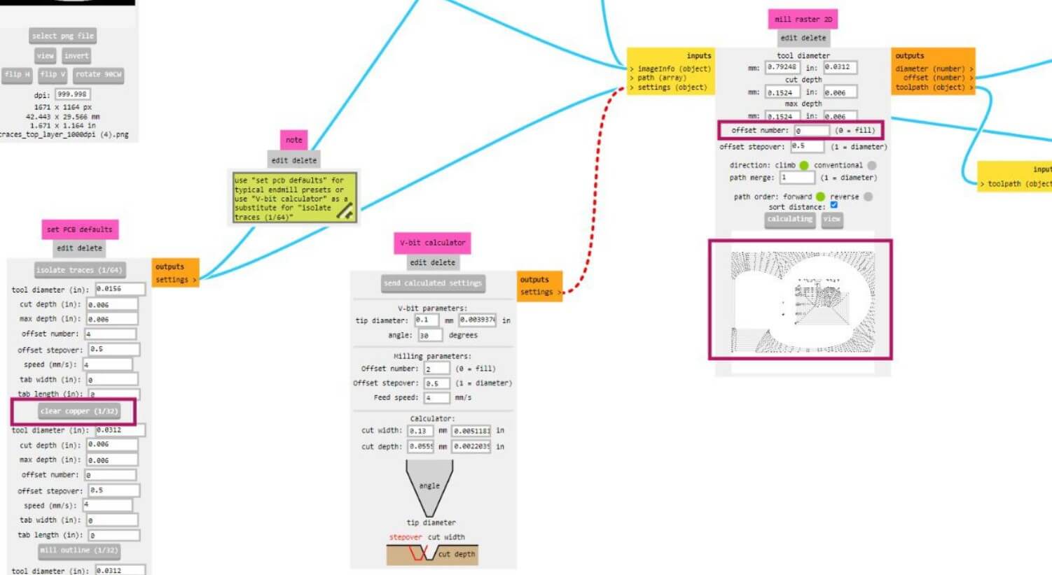
For the fabrication of the pcb board I use the Roland Modela pro MDX-540 machine from the Fab Lab Universidad de Lima as I learn to use in week 8.
After having the design of the pcb board and the gcode file I had to cut and sold every component in the board. The components I used were:
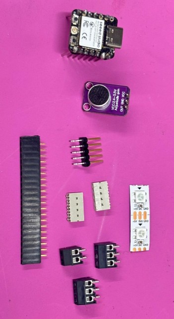
some components
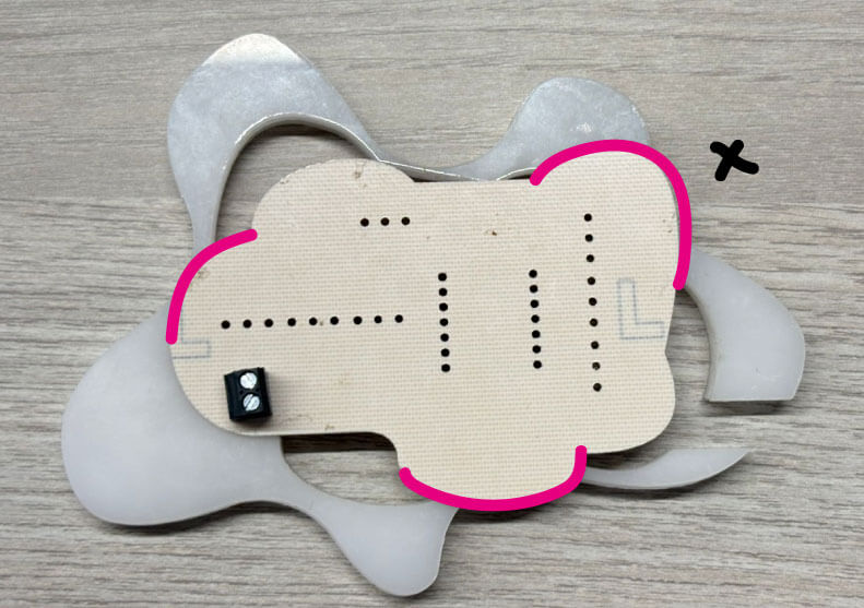
I gave the base pcb board 10 passes to clear enough the roads. Then I turned it upside down to sold the terminal blocks.
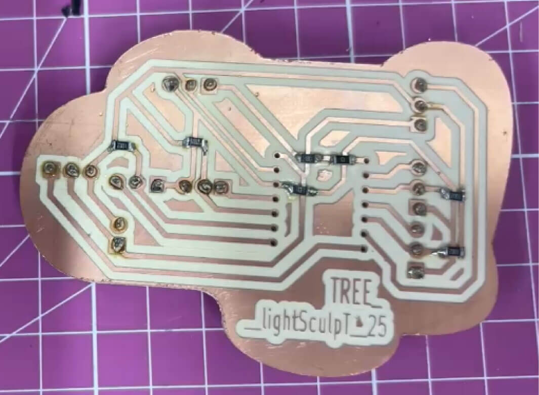
Back side pcb board

Front side pcb board
soldering process
2. 3D printed b r a n c h e s
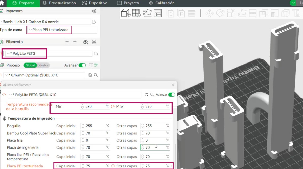
For the branches I choose a translucent material so it can be see trough but not at all and also reflect the light of the leds inside. I use transparent PETG and a 3d printer Bambu Lab Studio.
I had to change the settings as I had to print the pieces in vertical to not have supports inside since they are hollow and have no filling, the cables and LED strips will pass through inside. Basically I change the temperature of the base to stick better (because in the first tests it was printing in the air)
upside down pcb board
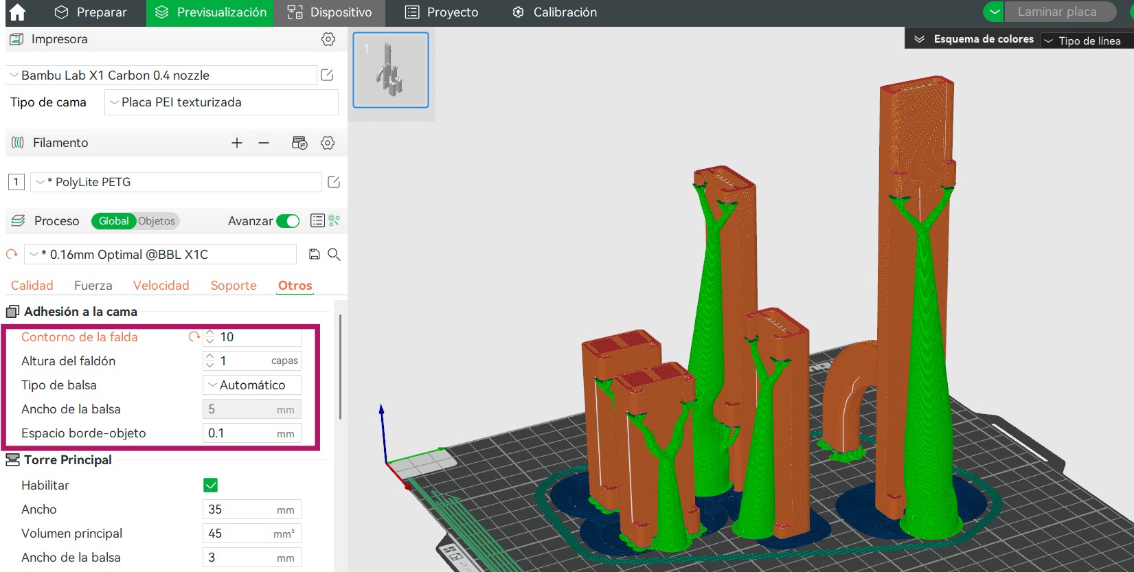
And also in the supports I gave it more bed adherence changing this settings:
upside down pcb board
The printing last 10 hours in a set of 2 of 5 hours. I printed everything with 0.16 layers thickness. It had a tolerance of 0.03mm to fit with the aluminium piece.
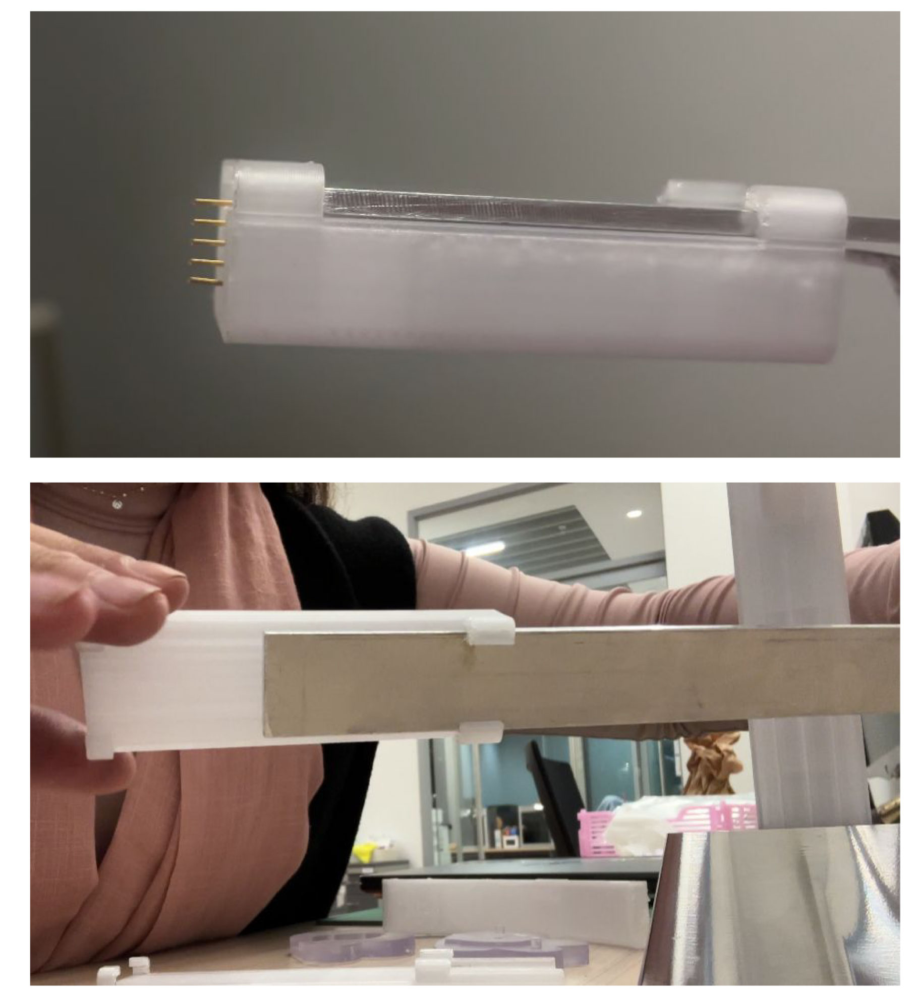
branches fit
3d printing process
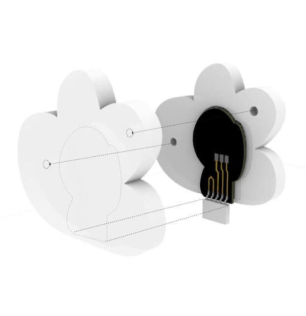
3. r e s i n P e t a l s + b o a r d s
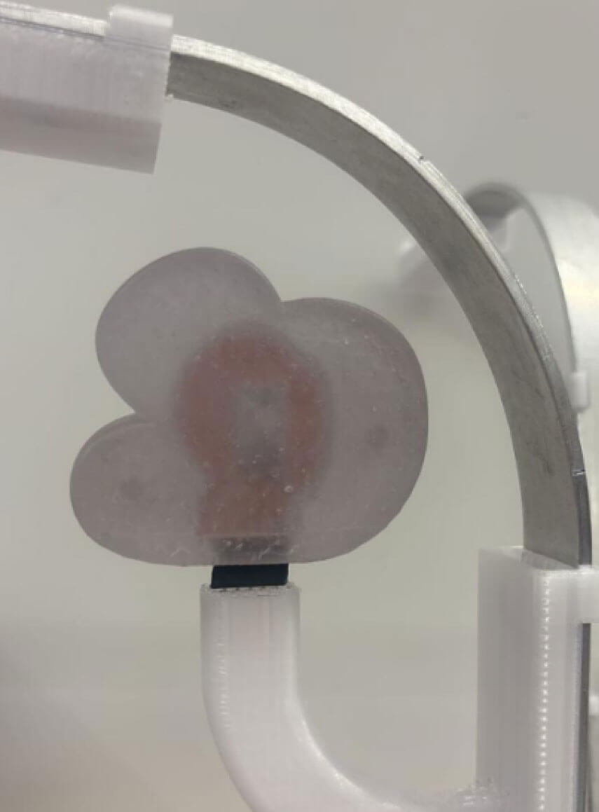
The petals were made in two processes: the 3d printing in clear resin and the pcb boards of each led. The 3d printings were made in two parts so it can fit the boards. Also it had a hole to fit the pin socket in the outside.
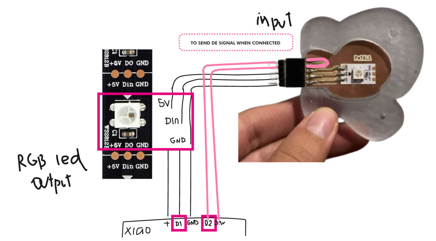
petals input and output system
resin 3D p r i n t i n g
For the 3d printing in clear resin I use the Phrozen Sonic Mega 8K Resin 3D Printer I tried in week 5. I prepared the file in Chitubox were I import the models and rotate them 45° so they do not stick to the base. I also gave it a skate support base and auto supports.
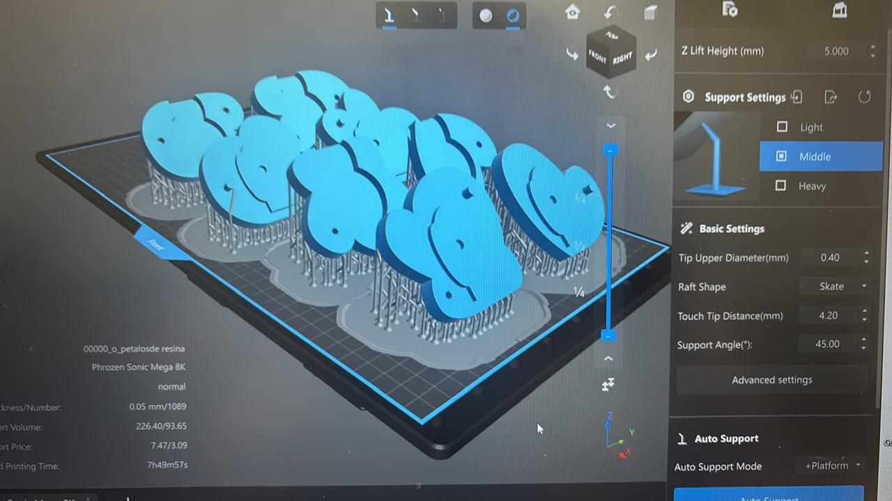
chitubox settings
It last 14 hours to print the 8 parts at once and they did not fall since the printing is upside down. Also I maintain the fill in the model so the layers of resin can difuse the light of the led inside.
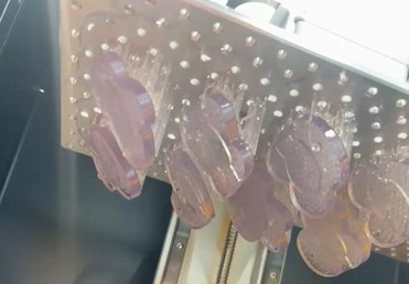
printing process
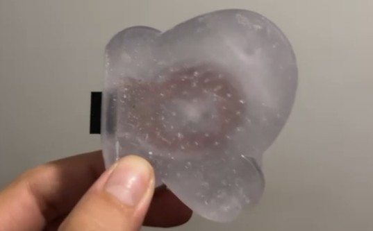
The finish of the resin and the supports leave a light texture. The board fit well in the negative piece.
Base pcb board
petals pcb board
p e t a l Bo a r d
For boards inside each petal I also made small boards for the pin headers that will fit inside the end of 2 branches to be more stable to assembly.
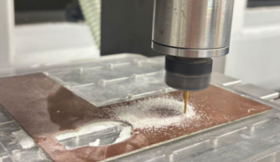
cutting the boards in the Roland machine
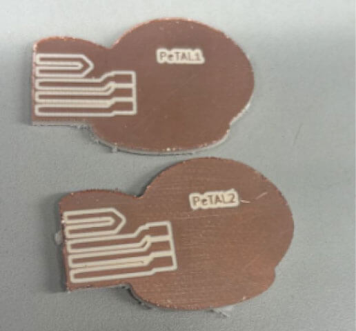
pcb boards
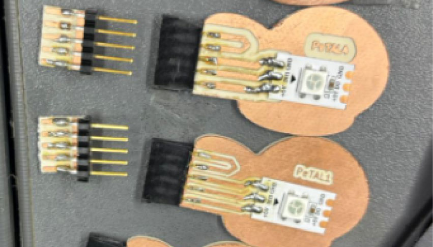
petals pcb boards with the other pin headers boards
4. a s s e m b l y
After having all the pieces fabricated I had to assembly everything in order to finish solding everything to the base pcb board and each cable passes inside the branches.
pieces made
One branch assembled
petal detail
manual fit with the pin header and socket in the petals
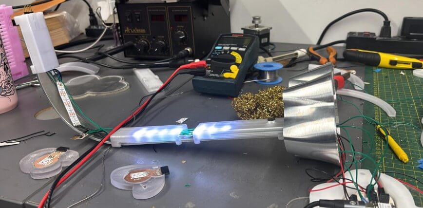
a s s e m b l y E l e c t r o n i c s
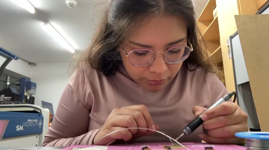
After confirming that everything fit well and no pieces were missing, I opened all the branches and began to pass the cables and solder the LED strip, adjusting it from the base terminals to the last pin headers. First I assembled one branch with everything and the cables to test the continuity with a multimeter and then testing the code.
cutting the boards in the Roland machine
p r o g r a m m i n g
Following some tutorials to know how to manage the led strip I found this tutorial that had a base to turn on a rgb led strip with NeoPixel library in Arduino. I first made a code to turn 4 colors in a specific order from the colors I found the combination RGB in week 10 Output devices.
4 color combinations
#include <Adafruit_NeoPixel.h>

#define PIN1 D6
#define PIN2 D5
#define NUMPIXELS 16

Adafruit_NeoPixel strip1(NUMPIXELS, PIN1, NEO_GRB + NEO_KHZ800);
Adafruit_NeoPixel strip2(NUMPIXELS, PIN2, NEO_GRB + NEO_KHZ800);

int pin = D9;
int pin1 = D8;
int pin2 = D2;
int pin3 = D4;


void setup() {
  Serial.begin(9600);
  pinMode(pin, INPUT);
  pinMode(pin1, INPUT);
  pinMode(pin2, INPUT);
  pinMode(pin3, INPUT);


  strip1.begin();
  strip2.begin();
}

void setColorBothStrips(uint8_t r, uint8_t g, uint8_t b) {
  for (int i = 0; i < NUMPIXELS; i++) {
    strip1.setPixelColor(i, strip1.Color(r, g, b));
    strip2.setPixelColor(i, strip2.Color(r, g, b));
  }
}

void loop() {
  bool a = digitalRead(pin);
  bool b = digitalRead(pin1);
  bool c = digitalRead(pin2);
  bool d = digitalRead(pin3);

  if (!a && !b && !c && !d) {
    setColorBothStrips(255, 255, 255); // WHITE
  } else if (a && !b && !c && !d) {
    setColorBothStrips(255, 105, 180); // PINK
  } else if (a && b && !c && !d) {
    setColorBothStrips(128, 0, 128); // PURPLE
  } else if (a && b && c && !d) {
    setColorBothStrips(0, 255, 255); // SKY BLUE
  } else if (a && b && c && d) {
    setColorBothStrips(0, 0, 255); // BLUE
  } else {
    setColorBothStrips(0, 0, 0); // TURN OFF
  }

  strip1.show();
  strip2.show();

  delay(50);
}
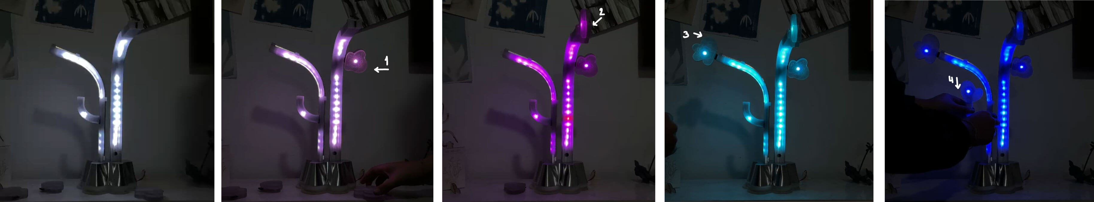
The final code includes variations of the 4 main colors and has a total of 16 color combinations between the 4 petals.
16 color combinations
#include <Adafruit_NeoPixel.h>

#define PIN1 D6
#define PIN2 D5
#define NUMPIXELS 16

Adafruit_NeoPixel strip1(NUMPIXELS, PIN1, NEO_GRB + NEO_KHZ800);
Adafruit_NeoPixel strip2(NUMPIXELS, PIN2, NEO_GRB + NEO_KHZ800);

int pin = D9;
int pin1 = D8;
int pin2 = D2;
int pin3 = D4;

void setup() {
  pinMode(pin, INPUT);
  pinMode(pin1, INPUT);
  pinMode(pin2, INPUT);
  pinMode(pin3, INPUT);
}

void setColorBothStrips(uint8_t r, uint8_t g, uint8_t b) {
  for (int i = 0; i < NUMPIXELS; i++) {
    strip1.setPixelColor(i, strip1.Color(r, g, b));
    strip2.setPixelColor(i, strip2.Color(r, g, b));
  }
}

void loop() {
  bool a = digitalRead(pin);
  bool b = digitalRead(pin1);
  bool c = digitalRead(pin2);
  bool d = digitalRead(pin3);

  if (!a && !b && !c && !d) {
    setColorBothStrips(255, 255, 255); // WHITE
  } else if (!a && !b && !c && d) {
    setColorBothStrips(255, 200, 255); // PINK 1
  } else if (!a && !b && c && !d) {
    setColorBothStrips(255, 150, 255); // PINK 2
  } else if (!a && !b && c && d) {
    setColorBothStrips(255, 100, 255); // PINK 3
  } else if (!a && b && !c && !d) {
    setColorBothStrips(200, 100, 255); // MAGENTA 1
  } else if (!a && b && !c && d) {
    setColorBothStrips(180, 70, 255); // MAGENTA 2
  } else if (!a && b && c && !d) {
    setColorBothStrips(160, 50, 255); // PURPLE PINK
  } else if (!a && b && c && d) {
    setColorBothStrips(120, 0, 255); // PURPLE
  } else if (a && !b && !c && !d) {
    setColorBothStrips(100, 150, 255); // SKY BLUE 1
  } else if (a && !b && !c && d) {
    setColorBothStrips(80, 170, 255); // SKY BLUE 2
  } else if (a && !b && c && !d) {
    setColorBothStrips(60, 190, 255); // SKY BLUE 3
  } else if (a && !b && c && d) {
    setColorBothStrips(40, 210, 255); // BLUE SKY BLUE
  } else if (a && b && !c && !d) {
    setColorBothStrips(20, 100, 255); // BLUE 1
  } else if (a && b && !c && d) {
    setColorBothStrips(0, 50, 255); // BLUE 2
  } else if (a && b && c && !d) {
    setColorBothStrips(0, 0, 255); // BLUE PURPLE
  } else if (a && b && c && d) {
    setColorBothStrips(0, 0, 180); // BLUE PURPLE 2
  } else {
    setColorBothStrips(0, 0, 0); // TURN OFF
  }

  strip1.show();
  strip2.show();
  delay(50);
}
i n A c t i o N f i r st T e s t s
I first test one branch assembled and a simple code of the same structure but with a change of two colors: red and green.
first test of 1 change color
second test with 3 change colors
f i n a l T e s t
After the code's functionality was confirmed, I finished assembling the entire project to close it and test the final code. First I checked all the leds were turning on and everything still fits as shown in the video above:
i t W o r k s !!!
m a i n C o l o r C o m b i n a t i o n s
f i n a l P r e s e n t a t i o n
still ... what's next?
Test the microphone to control the brightness of the colors once the color combination is defined by the petals. And of course to make more light sculptures!
f i r st T e s t s
first test of 1 change color
second test with 3 change colors
f i n a l T e s t
i t W o r k s !!!
m a i n C o l o r C o m b i n a t i o n s