Assignments
Design and produce something with a digital fabrication process (incorporating computer-aided design and manufacturing) not covered in another assignment, documenting the requirements that your assignment meets, and including everything necessary to reproduce it.
f a b r i c a t i o n I n M e t a l
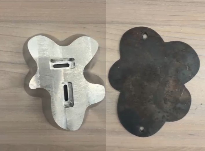
final products made in metal
All this weeks I have seen in the fablabUlima this big machines that worked with metal. Of course for heavy fabricaton processes. And I did really wanted to try making something like an metal sculpture.
d e s i g n
final products made in metal
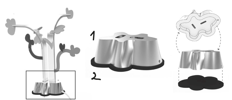
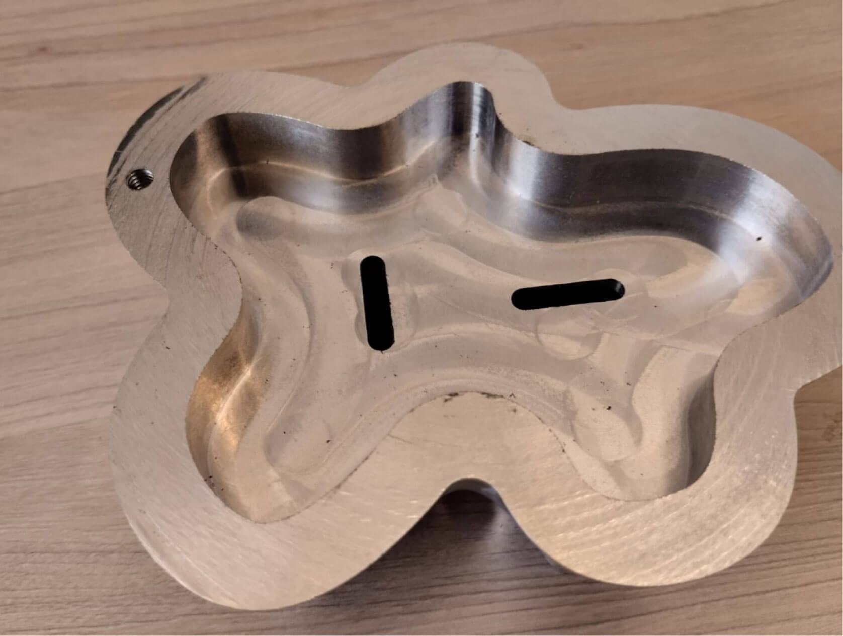
Since I already had the formal design for my final project, one of the big questions was how to make it stable enough to accommodate the changing pieces. So, having the option of making something metallic, I thought about making the two base pieces out of aluminum. This base is hollow inside because it needs to house the PCB and the beginning of all connections. It also has a hole through which the power supply cable will exit.
design process
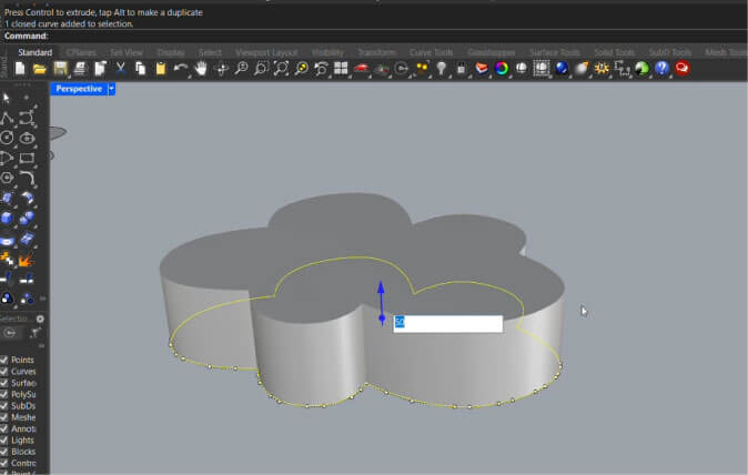
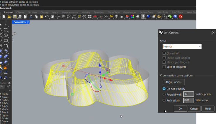
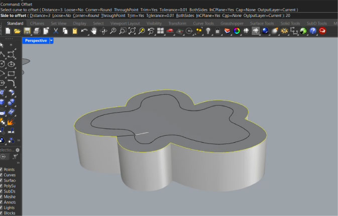
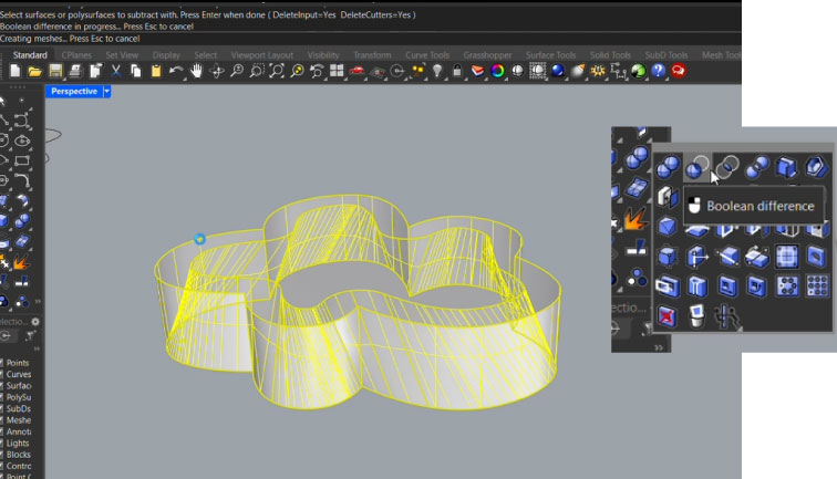
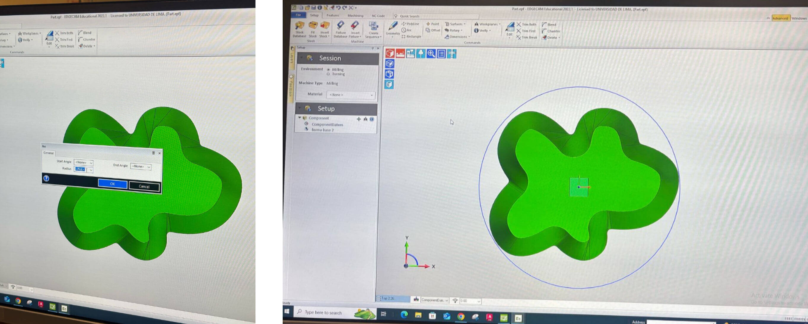
Rhinoceros modeling: I start from the external silohuette. Then extrude it because is really important to have the object as a solid and not just as external surfaces. So, I loft another offset curve and make it difference from the extrusion.
export file
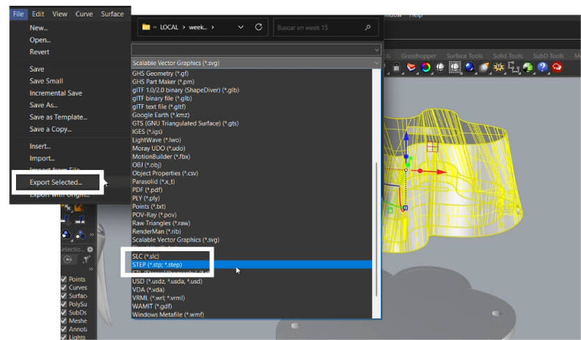
For the Kitamura 5 axis machine the file has to be exported in . STEP and for this is really important for it to be solid. For the other base, as it will be cut in the plasma cutter I just export it as .dxf and jut need the silhouette for this.
final products made in metal
K i t a m u r a 5 axis
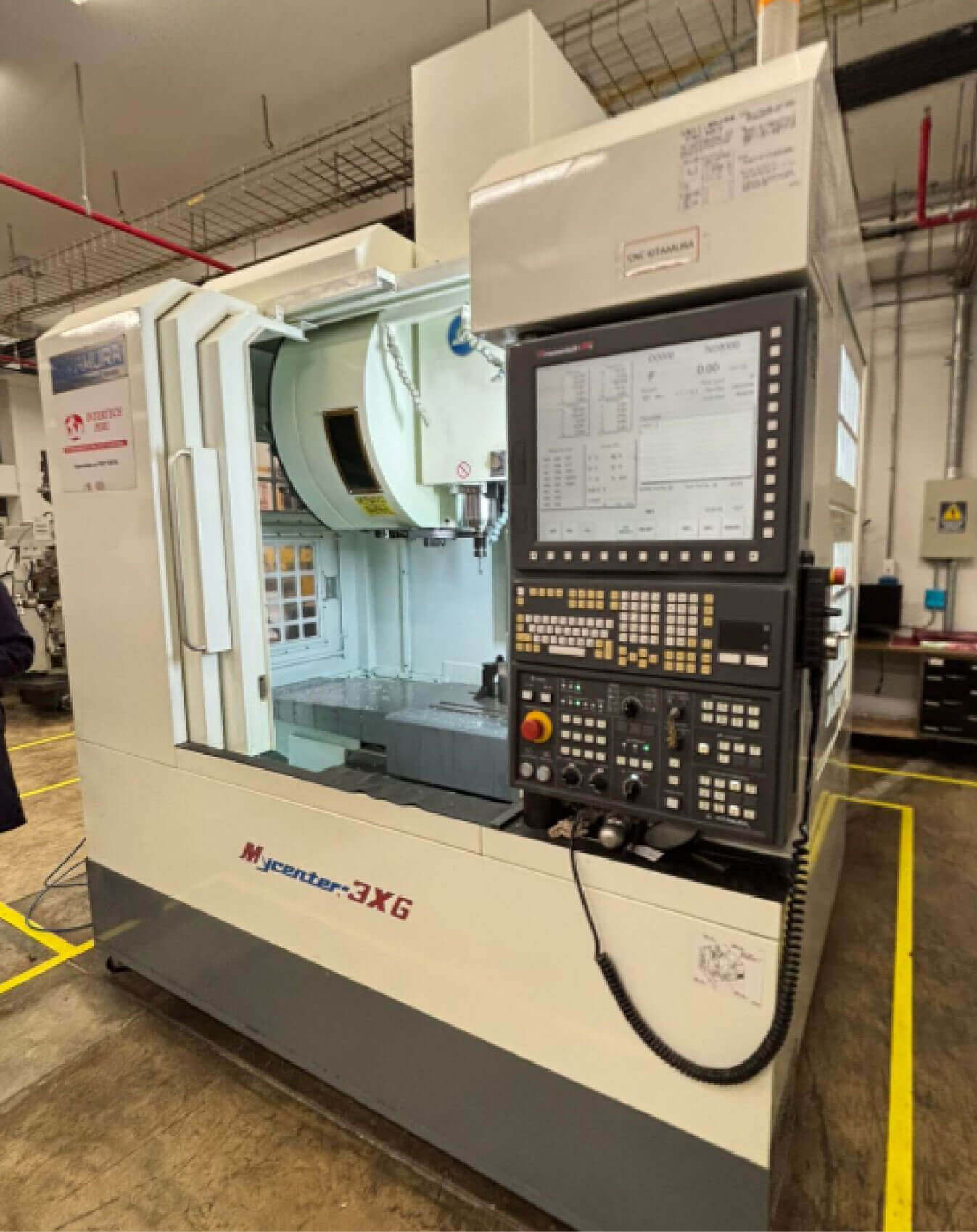
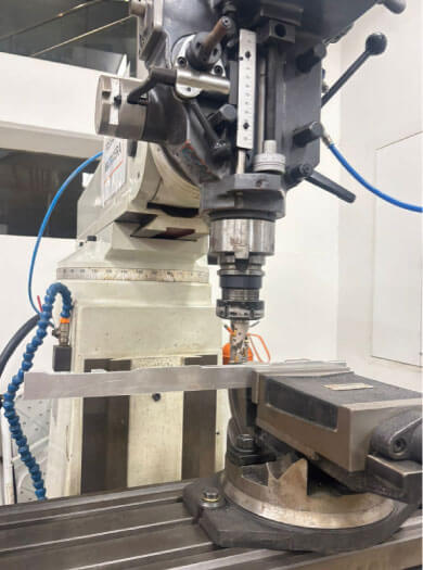
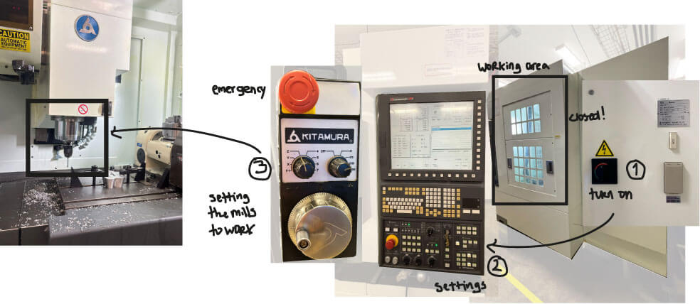
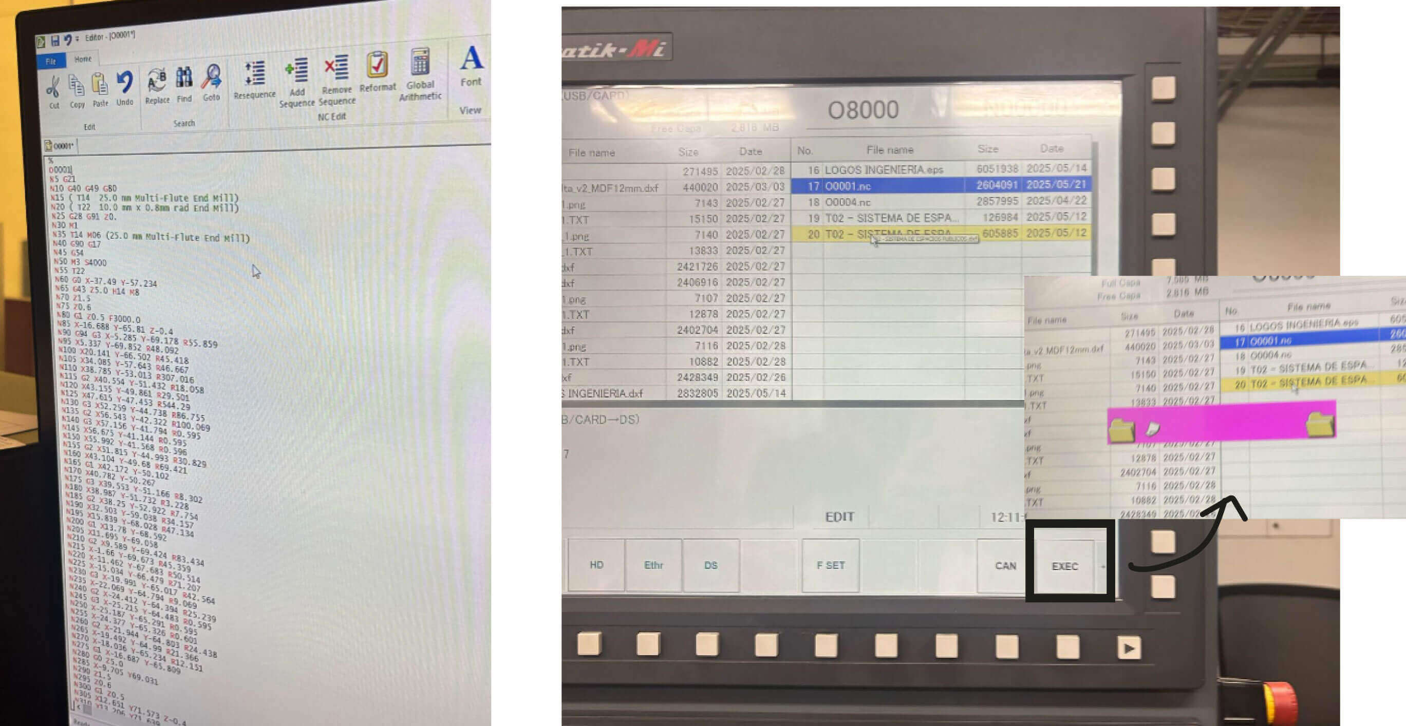
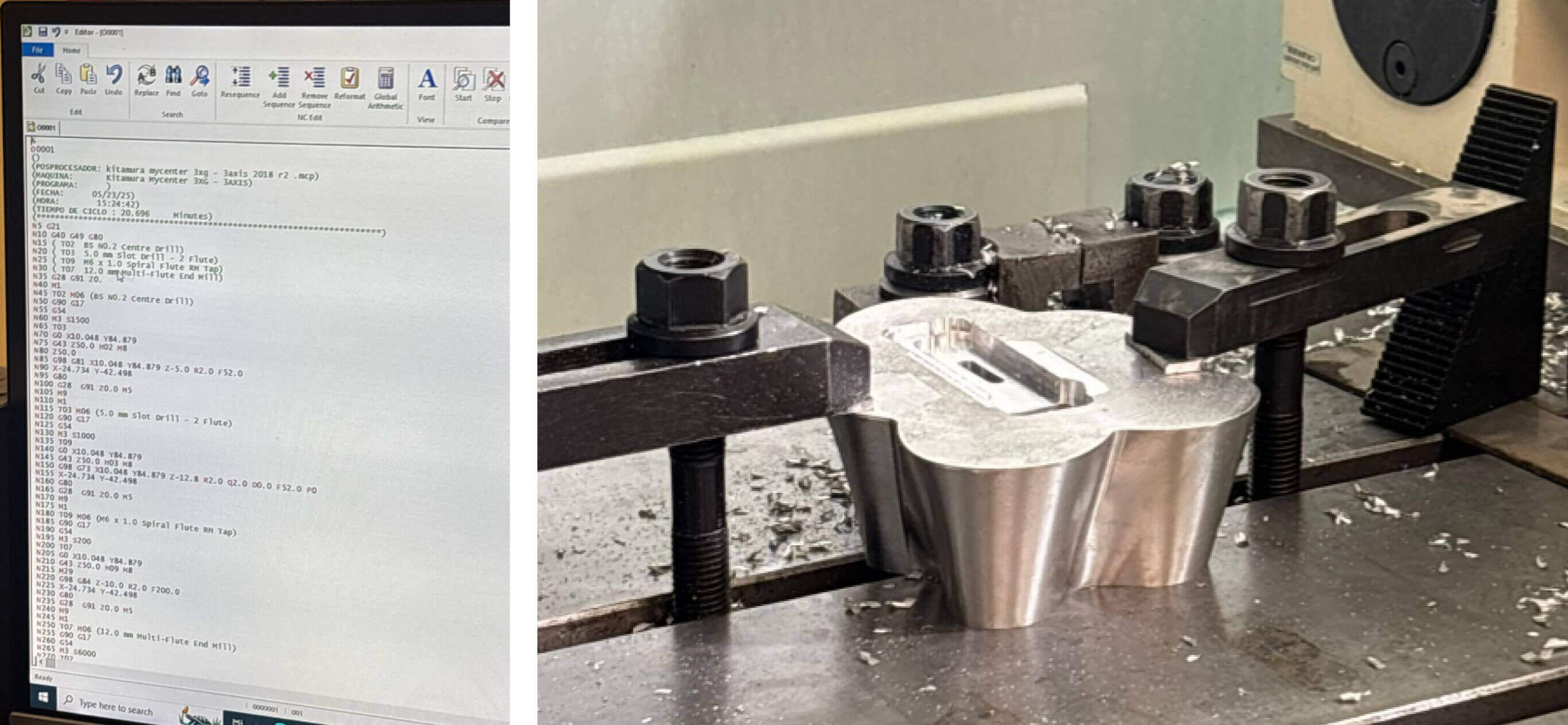
To use the Kitamura Mycenter 3XG 5-axis CNC mill from the lab I was guided by a mechanist that recommend me to do the base model in alumminium. He helped me to understand how to turn on the machine, to set the different mills choose in the g-code. and finally to understand the control panel.
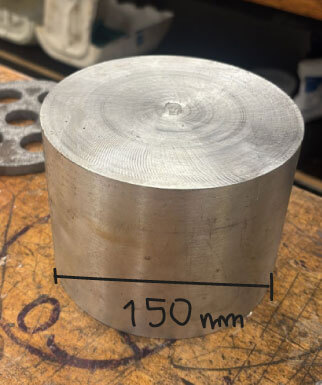
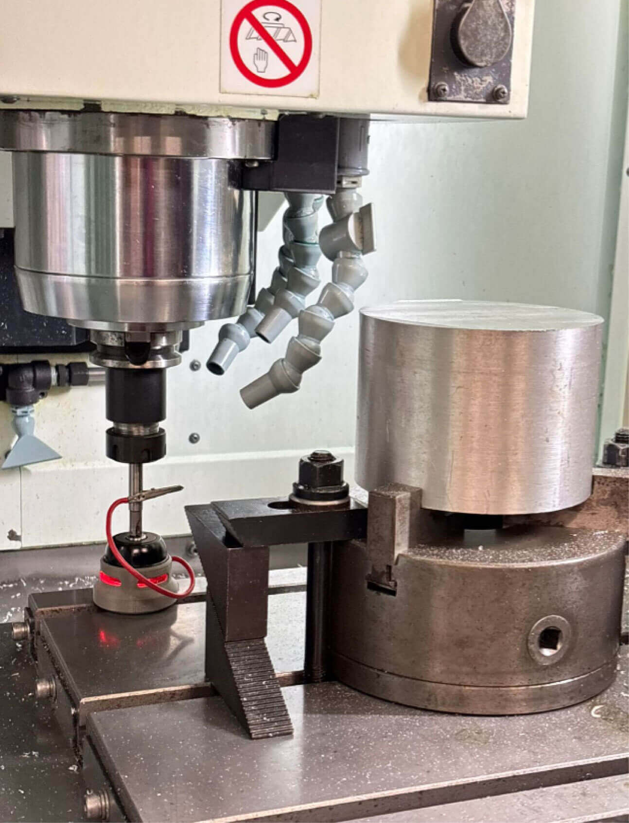
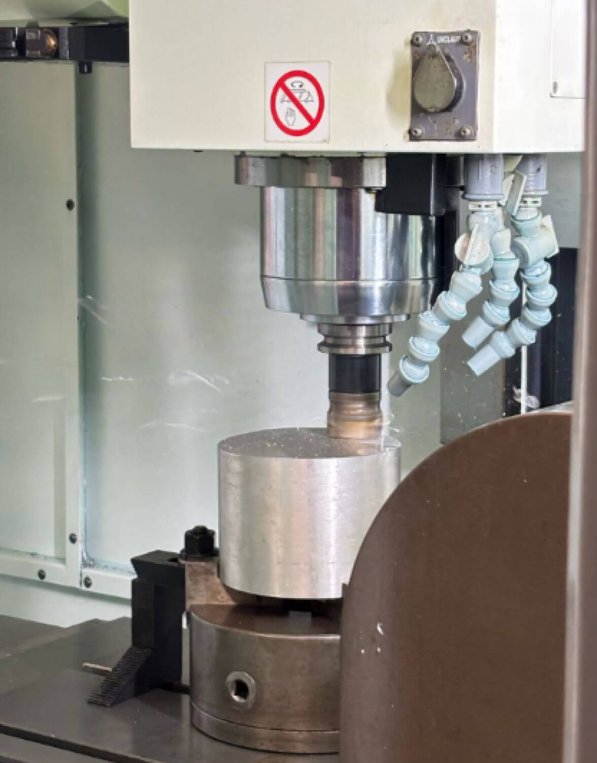
As they had a piece of 150mm of diammeter I fit the dimensions of my object in this piece. It end up using 150mm of diameter x 50mm of height.
For the model I made, I used three axes simultaneously, with different cutters. I used a fourth axis and another cutter to make the screws that will hold this piece to the other one I'll plasma cut.
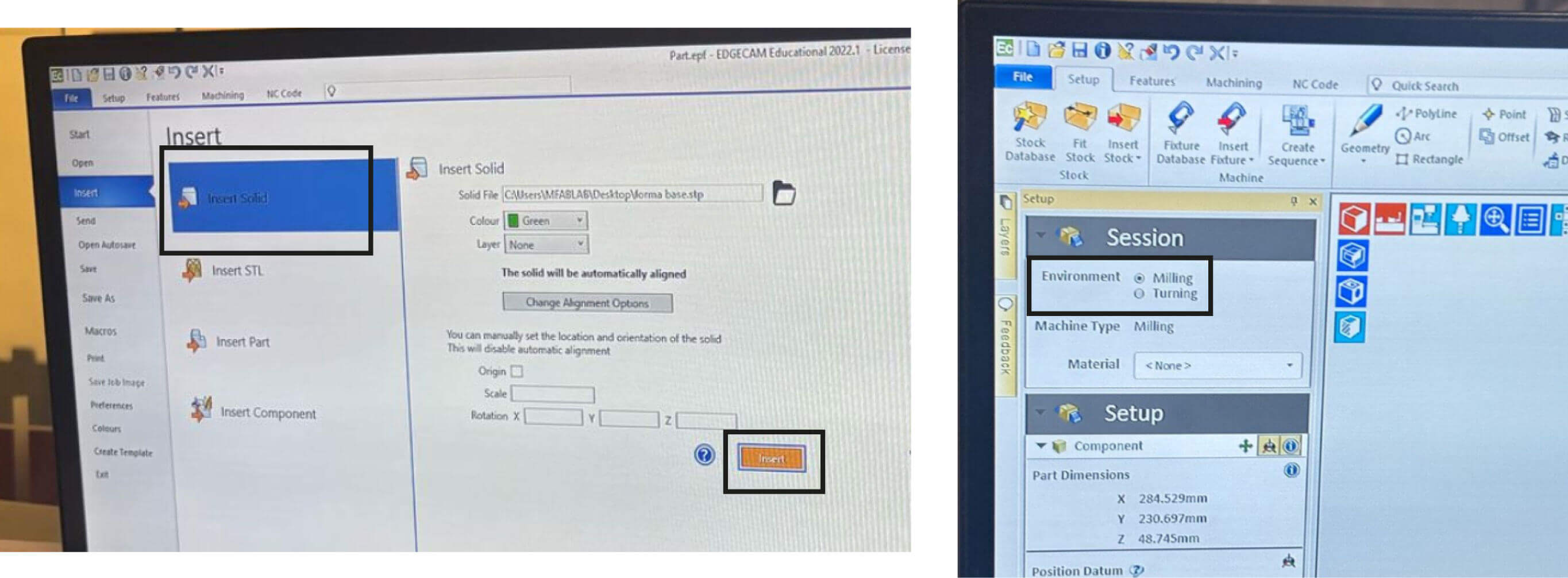
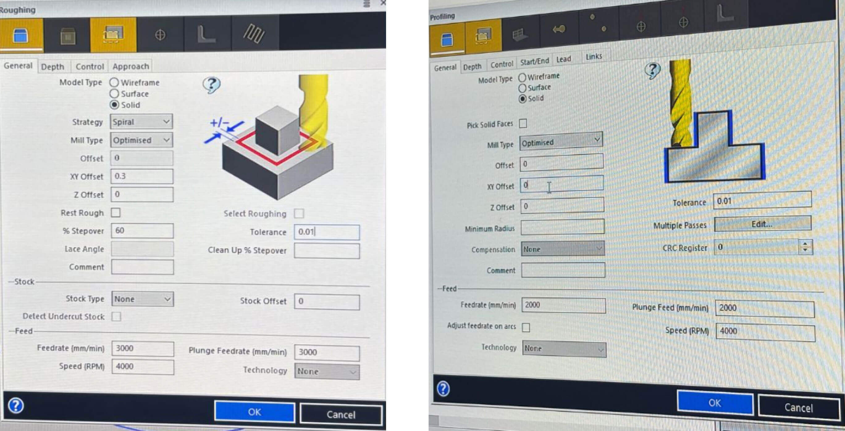
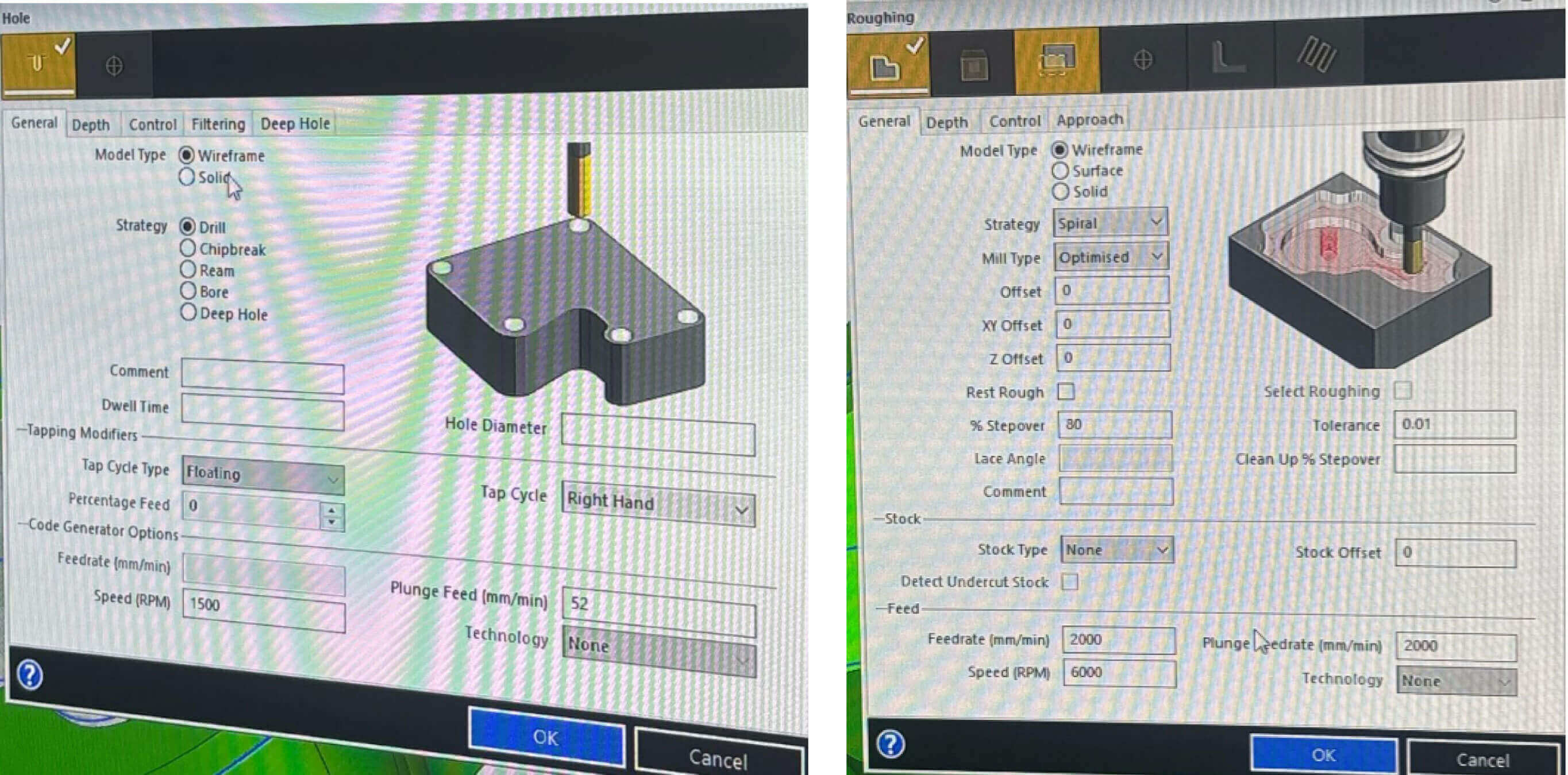
G-Code Generation with EDGECAM:
Job 1: exterior milling
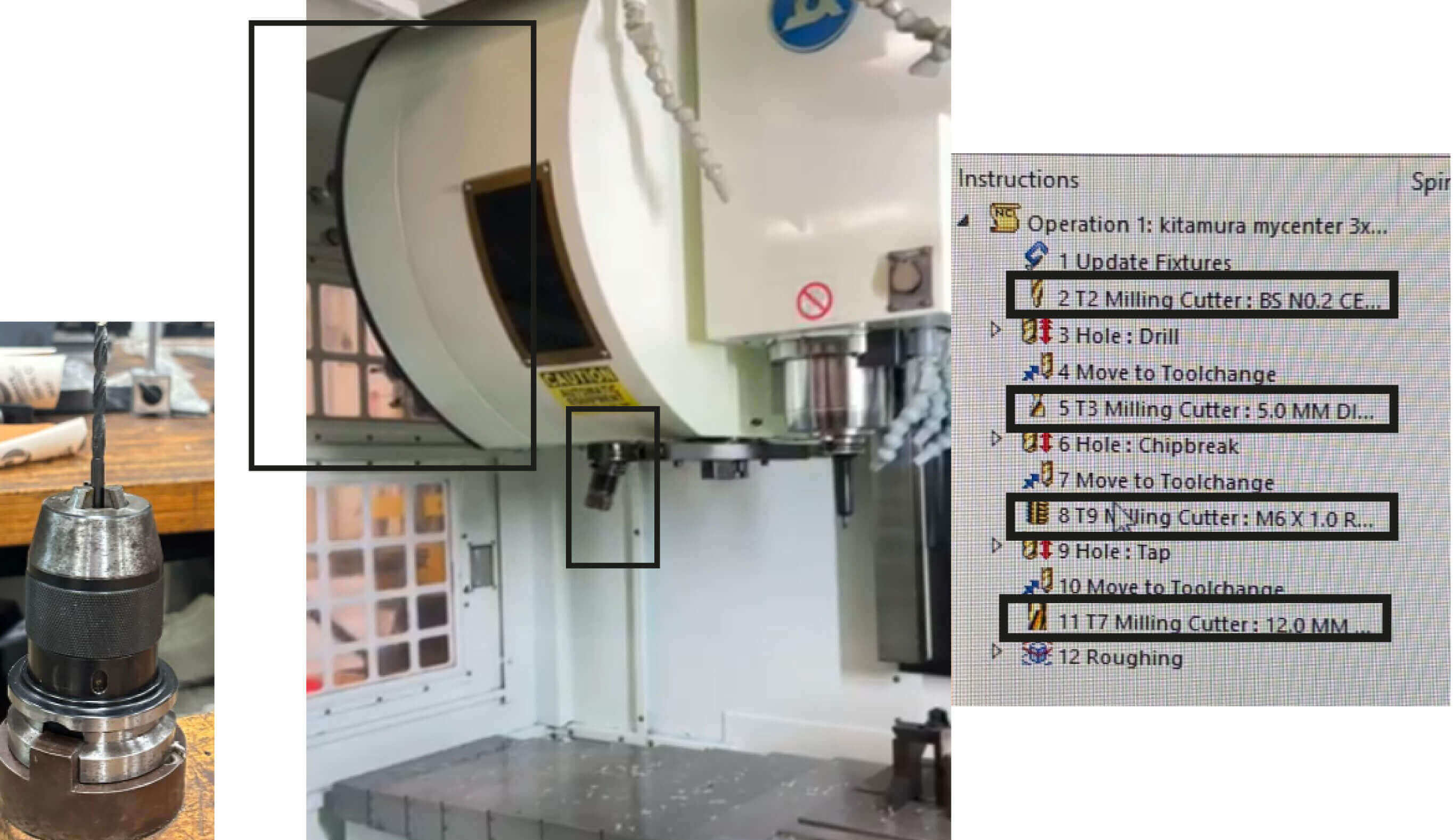
First I generate the g-code just for the milling process of the external form. For this process it used two mills simultaneously in 3 axis at the same time. For this I just export the solid base form in .step format.
In this machine you just set all the mills to use once.
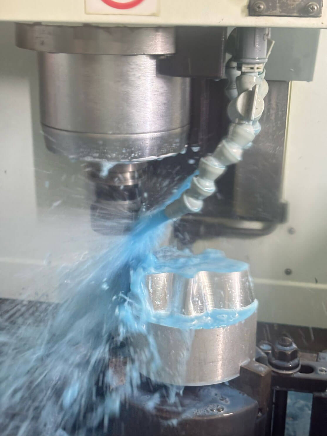
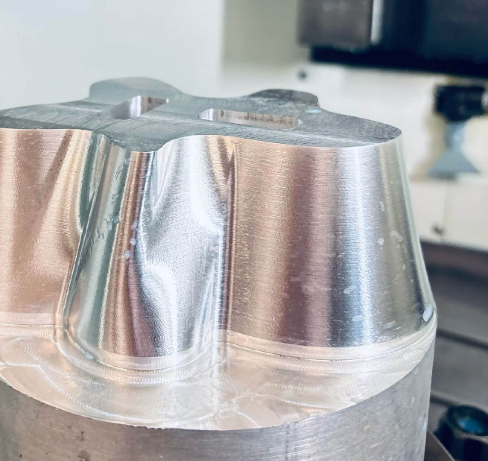
The machine expels a coolant as the aluminum heats up due to friction. That's why it's important to keep the machine closed and not open it during the process. There are pause buttons in case we notice anything unusual. Fortunately, nothing unusual happened during the cut, and it was ready in 3 hours. It was super smooth and was able to cut all the curves on the outer surface.
Job 2: interior milling
In this job I set all the interior milling cuts with 4 different mills simultaneous. I had to organize the mills in the machine (with the help of the mechanist) To put them in order as the g-code.
For this job I set the object upside down in the machine and set it from the borders. We got scared it could fall but happily it resisted.
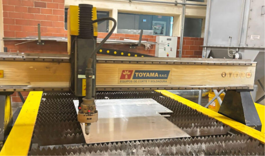
P l a s m a c u t t e r
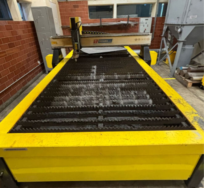
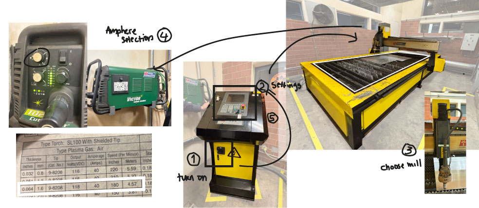
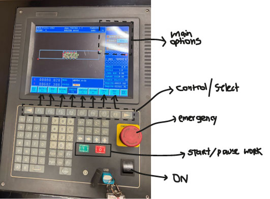
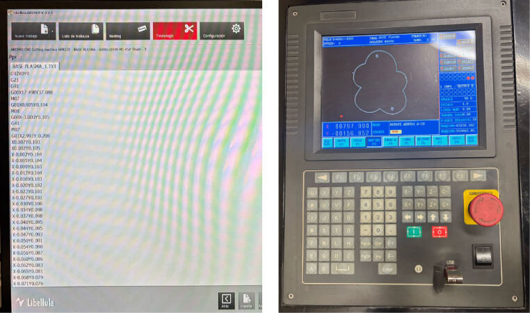
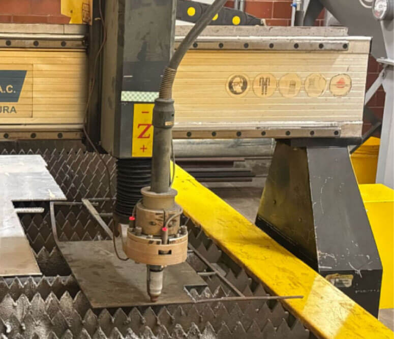
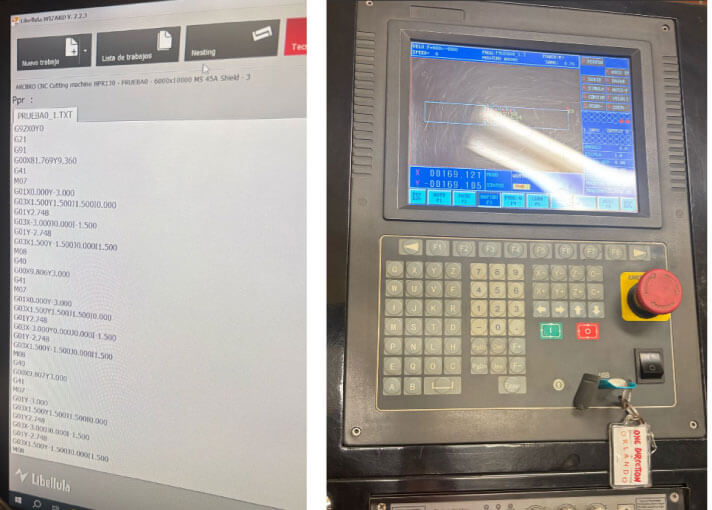
The plasma cutter works with amperes, which means it works with electricity. Through heat, it changes the state of the material; in other words, the gases ionize and conduct electricity and change the material state from solid and makes the cut. It has two setting stations. One like a pedestal to set the material and working place settings. And a second control station for the electricity.
 To use this machine, the laboratory has a special space, which must be closed during use, as sparks will fly. We must also wear protective equipment such as:
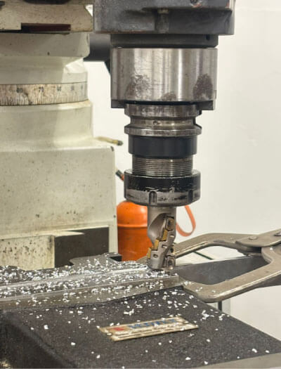
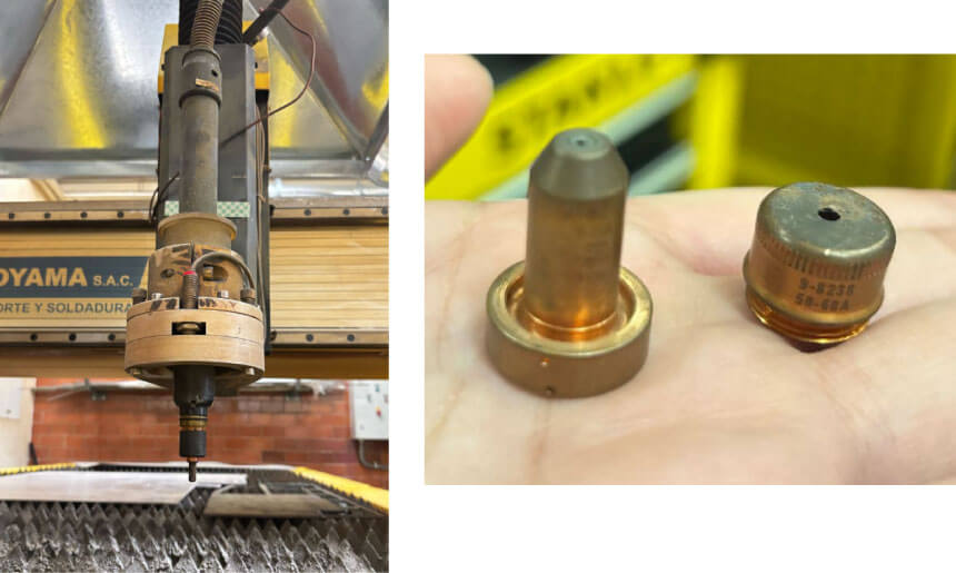
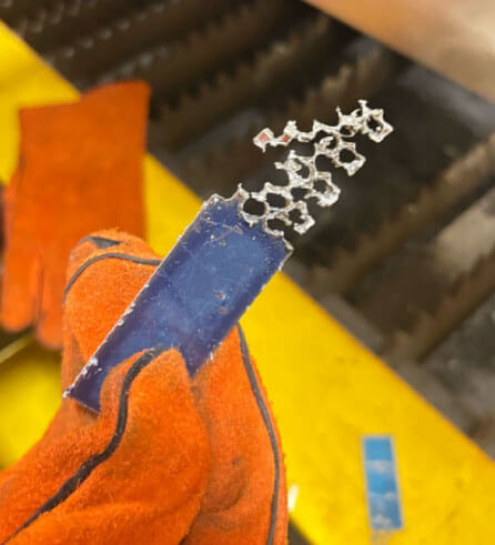
This machine doesn't use cutters as such, but rather nozzles. However, the cut didn't seem as clean for pieces as small as the one I sent. This is the nozzles I use for this tests.
G-Code Generation with LIBELLULA:
Job 1: Base
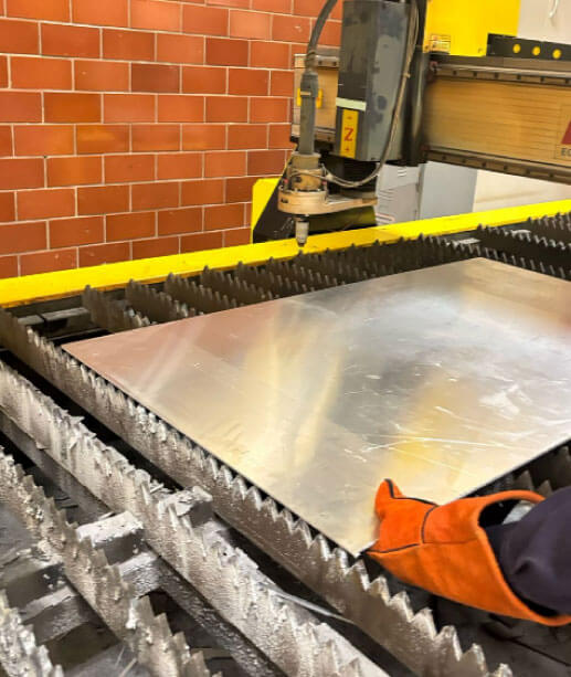
Using the same design, I cut the silhouette and holes for the base screws. I sent the file as a .dxf. I cut it out of 6mm mild steel which turned out to be heavier than I thought but ultimately what I needed.
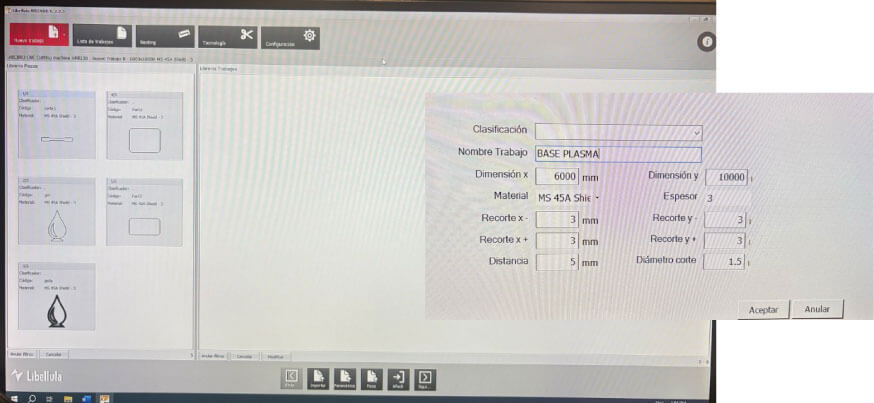
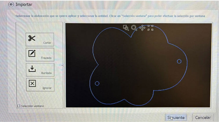
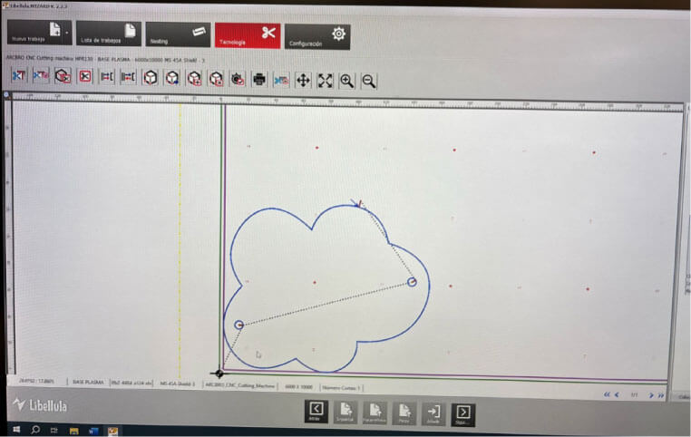
For G-code configuration, it's very similar to the Roland software and the CNC cutter. I open the DXF file and place it on axis 0. I check the cutting circuit and confirm it to open on the machine.
What's next?
As I really liked the finish in alumminium I think I could try to cut the exterior from the principal branches of the sculpture. However I need to bend the aluminum with a specific radius
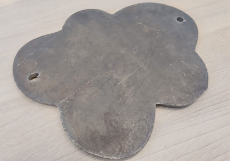
Update Job 2: Branches
Using the same design, I cut the silhouette and holes for the base screws. I sent the file as a .dxf. I cut it out of 6mm mild steel which turned out to be heavier than I thought but ultimately what I needed.
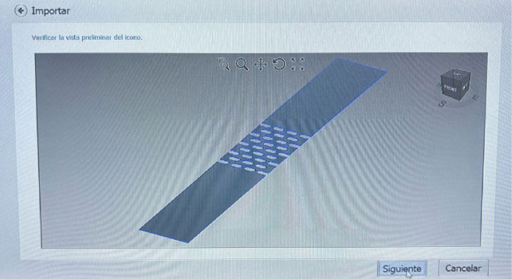
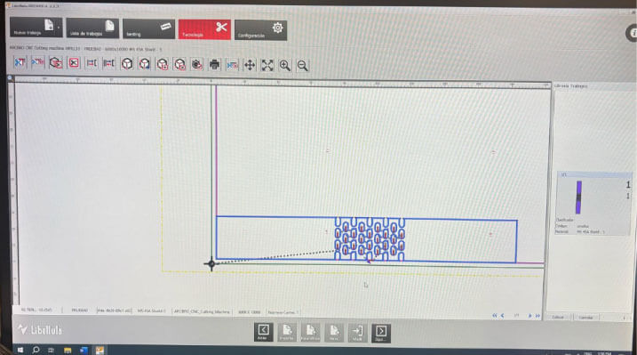
For G-code configuration, it's very similar to the Roland software and the CNC cutter. I open the DXF file and place it on axis 0. I check the cutting circuit and confirm it to open on the machine.
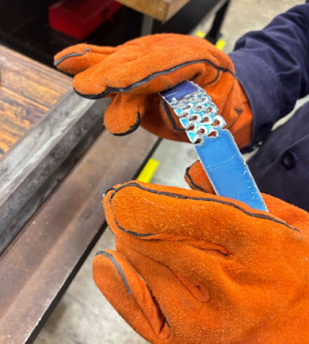
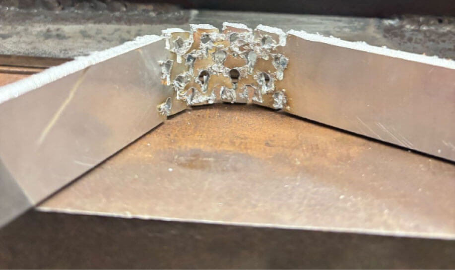
I had to make two tests because in the first the holes were too little. I made them from 2mm of diameter. For the second test I just send lines (where I wanted the hole). It did worked because was really easy to bend the aluminium but as the technist in the lab said, the aluminium is alredy easy to bend just need the correct tool. However as I wanted to control the radius to bend, this still is not perfect.
Update Job 2: Branches
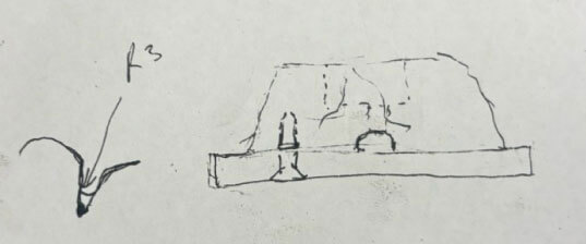
For a better finish, they recommended using a die cutter. It's a conventional milling machine to which we attach plates that are almost the size I need. We match them up, and then, using another machine, I bend it to the desired radius, which is approximately 107 mm.