
Assignments
Group Assignment
- Do your lab's safety training
- Characterize your lasercutter's focus, power, speed, rate, kerf, joint clearance and types.
Individual Assignment
- Cut something on the vinylcutter
- Design, lasercut, and document a parametric construction kit.
GROUP ASSIGNMENT
More specific detailed from the worked done with Ernesto Castro in Fab Lab Universidad de Lima here
Fab Lab Ulima s a f e t y t r a i n i n g
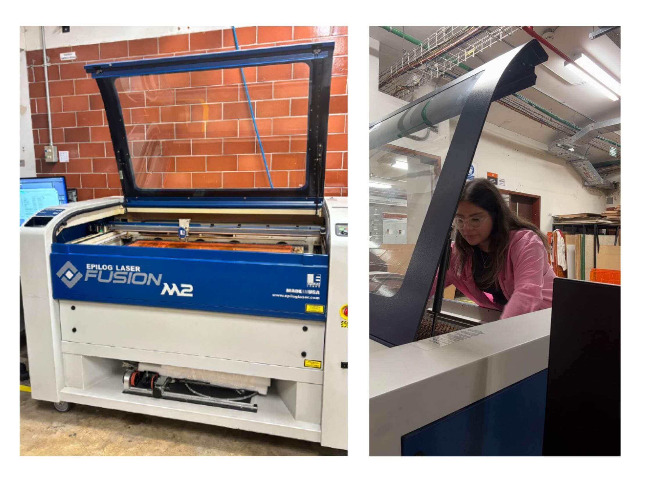
Setting the EPILOG LASER FUSION MS 30W.
The laser cutter that we have in the lab is the Epilog Laser Fusion M2 of 30 Watts for an area of 1000mmx70mm maximum. I have used before this machine in 2019 for the group studies of architecture students interested in digital fabrication called CEFADI. However I did an intro again with more detailed in how to used this machine.
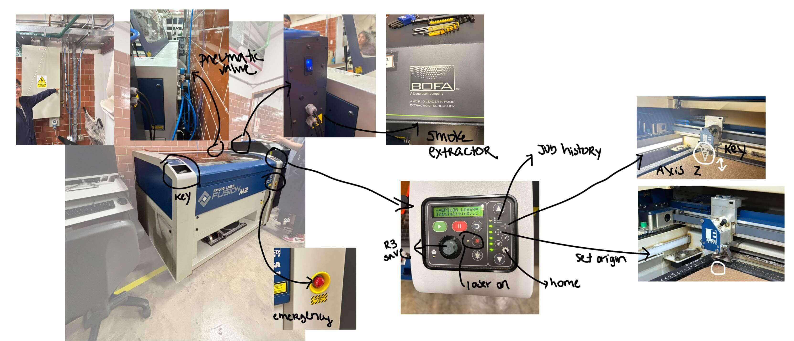
SETTINGS BEFORE CUTTING
So, to start using the laser cut First we have to set up everything in the machine an then on our document.
l a s e r c u t t e r material settings
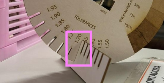
We did some tries in many materials to test the cut and engraving settings. Some of the materials I tried were acrylic and white cardboard.

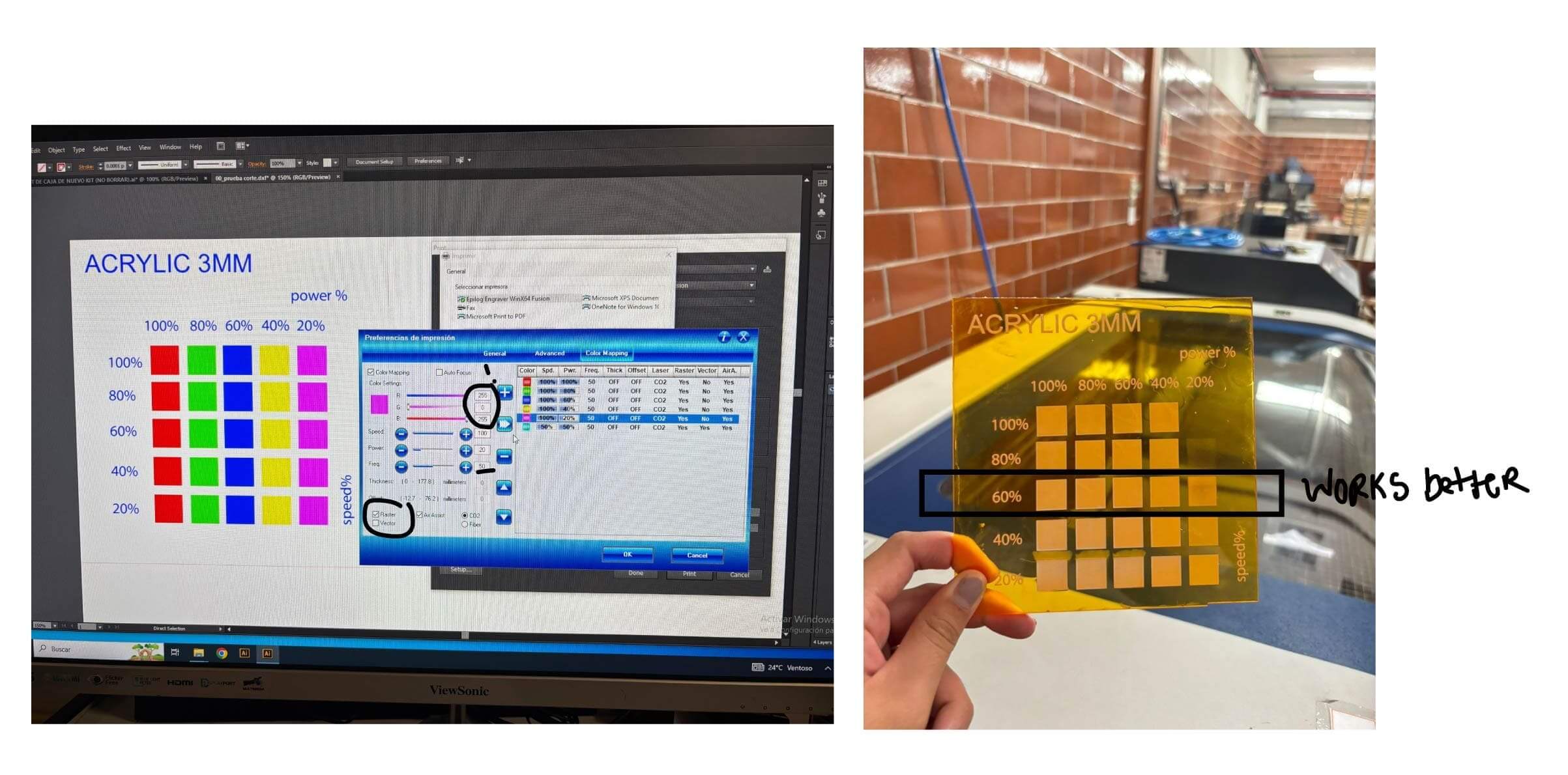
Once I understood the best settings for each material I did some final summary in this circles that also checked the tolerance of the material depending on its thickness. For example the white cardboard of 2mm fit with a space of 1.65mm. And the acrylics worked with a space of almost 2.50mm instead of 3mm.
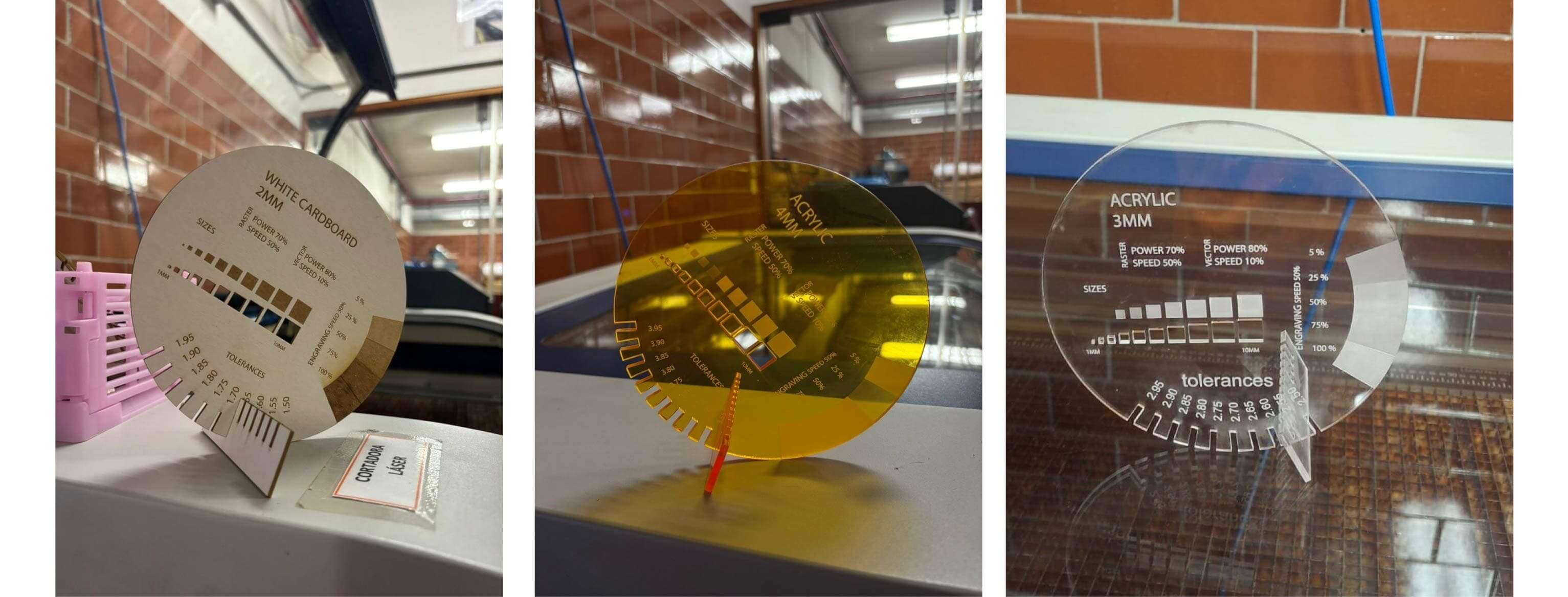
Final settings for white cardboard and acrylic
I also tried everything from flexible material and tolerance for joints in the white cardboard material for my parametric kit construction since I had lots of this material still util residue from my thesis model. So I wanted to try with this material I have been saving.
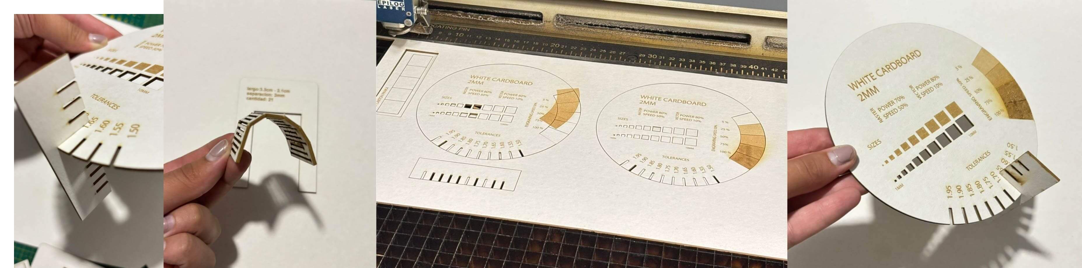
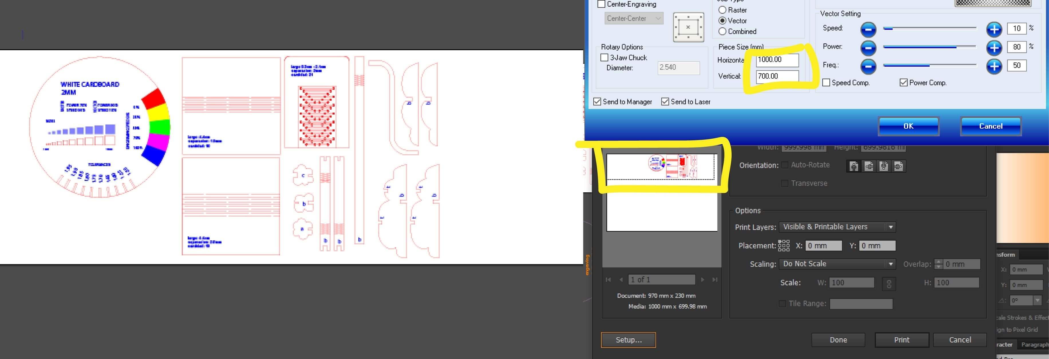 It was very important to check the spacework in the Illustrator archive (that is the software this laser cutter works in dxf documents) because when I first move the placement on Illustrator and it moved.
This happened because I did not checked if on the preference settings before printing the piece size (the space to cut) was smaller then the actual size of the space of 1000x700mm this machine has. Once I change this to the entire space values the preview updated and I could see all and not move anything manually on illustrator, because it changes everything on the settings!.
INDIVIDUAL ASSIGNMENT
v i n y l c u t t e r
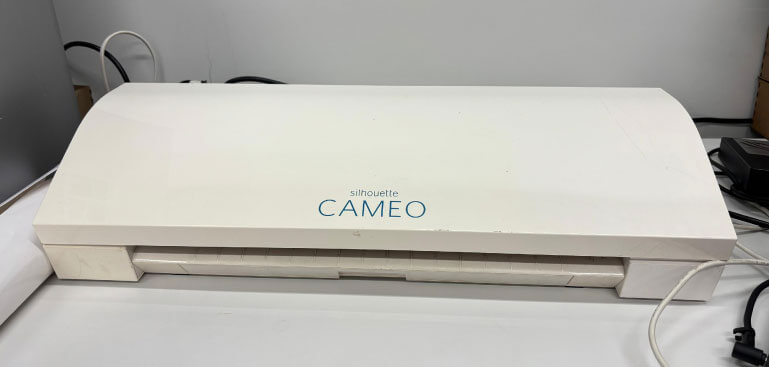
The vynil cutter in the lab is the Silouette CAMEO
I had used this machine in the CEFADI team in 2019 when I was in second year of undergraduate, where we made some masks in thin cardboard to see how we can make it fold exaclty where we wanted.
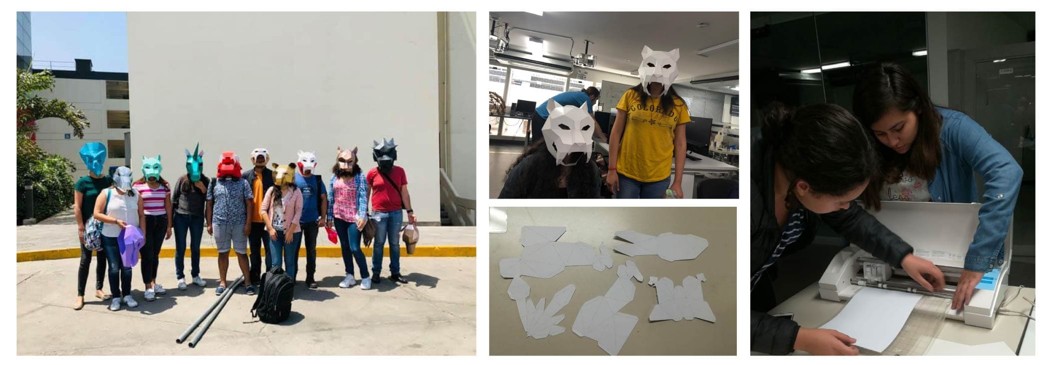
2019 tests in vynil cutter with thin cardboard
vynil s t r o k e s
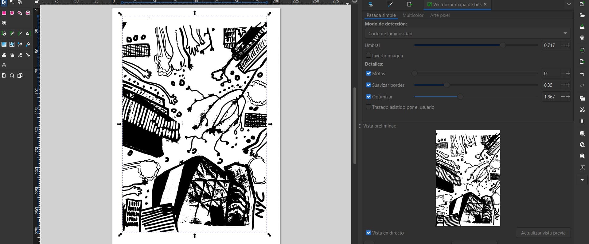
Vectors from my drawing
I wanted to cut the stokes of the digital drawing from my cyanotypes. So, I quickly got them on Inkscape. Here I got to adjust some figures by editing the umbral of the strokes to be more detailed or thinner. I select the less thinner so I can get more stroke area.
vynil p r o c e s s
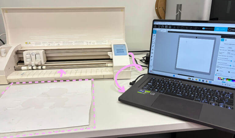
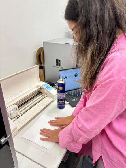
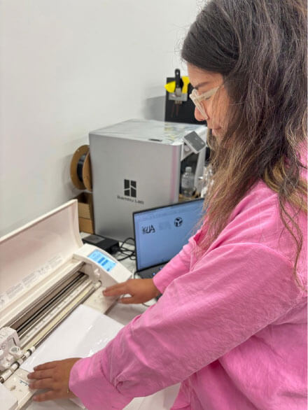
Cameo vynilcutter connected to the lab laptop
I had to select just one part of the entire stoke because the base of our vynil cutter was damaged and we had to improvise a new base. I put thick acetate from recomendation of the instructors and manually cut it. At first It looked like it wasn't thick enough as the original base because once it was charged it moved if the drawing was to small, since the the nozzle had to move a lot and very fast.
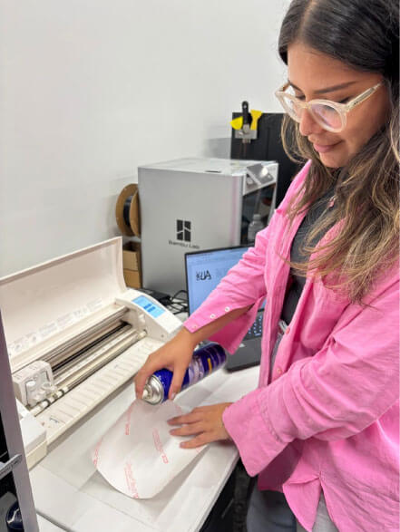
Spray the acetate
Paste the vynil
Insert it in the vynilcutter
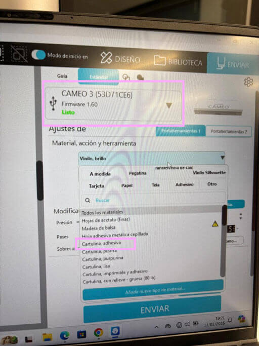
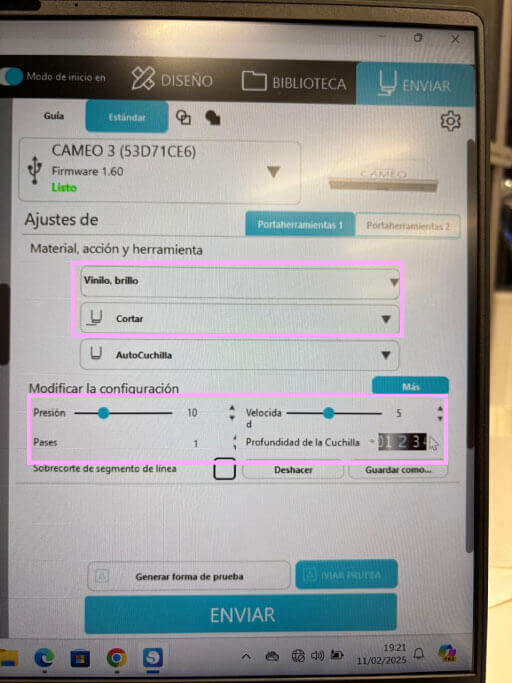
Then to manage the strokes to the vynilcutter I had to download Silhoutestudioto center the image in the machine and select the material and speed of cut:

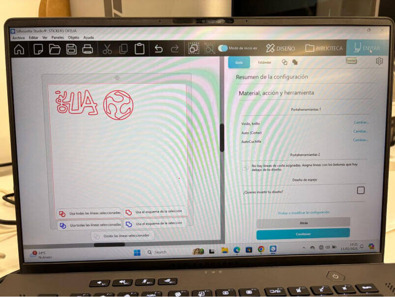
Import the strokes in .dxf
Material: in this case glossy vynil
To cut and the blase depth in this case 3.
The power and speed as the laser cutter. Here I didnt change the default settings since it is vynil.
Finally stick the material in the base and charge the material.
Adjust the material
Speed and precision
I had to select just one part of the entire stoke because the base of our vynil cutter was damaged and we had to improvise a new base. I put thick acetate from recomendation of the instructors and manually cut it.
At first It looked like it wasn't thick enough as the original base because once it was charged it moved if the drawing was to small, since the the nozzle had to move a lot and very fast.
Cameo vynilcutter connected to the lab laptop
Still I tried and finally I got that small sticker in my phone case.
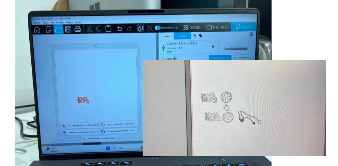
I only managed to cut some strokes and my name. However the big ones went wrong since I send another work smaller but didn't change the placement and cut over the one that went right. But I still got cool strokes from my drawing and my name in my laptop.
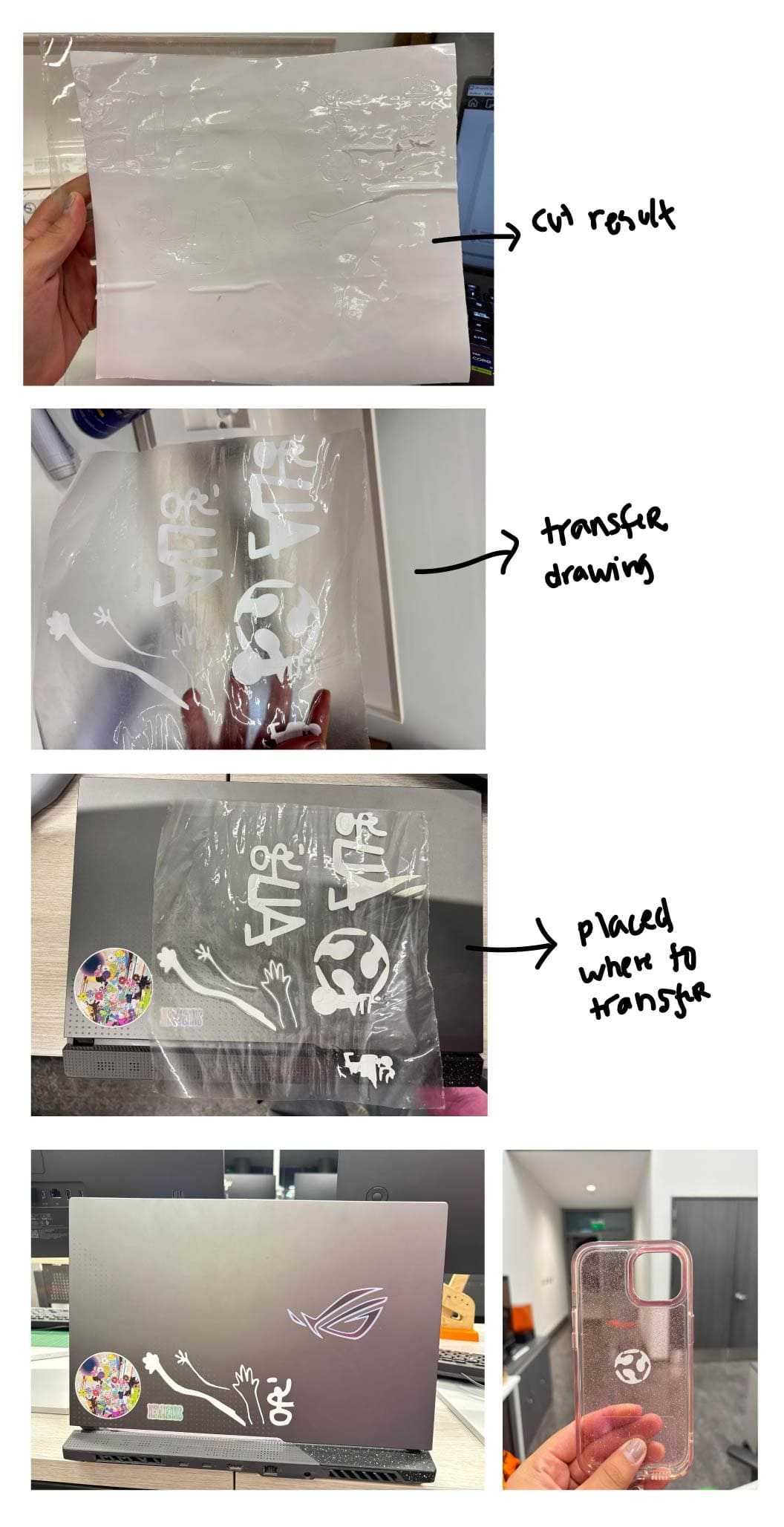
Transfer sticking process
p a r a m e t r i c C o n s t r u c t i o n K I T
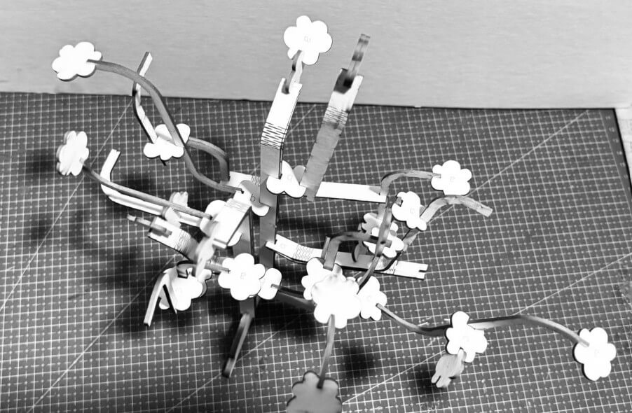
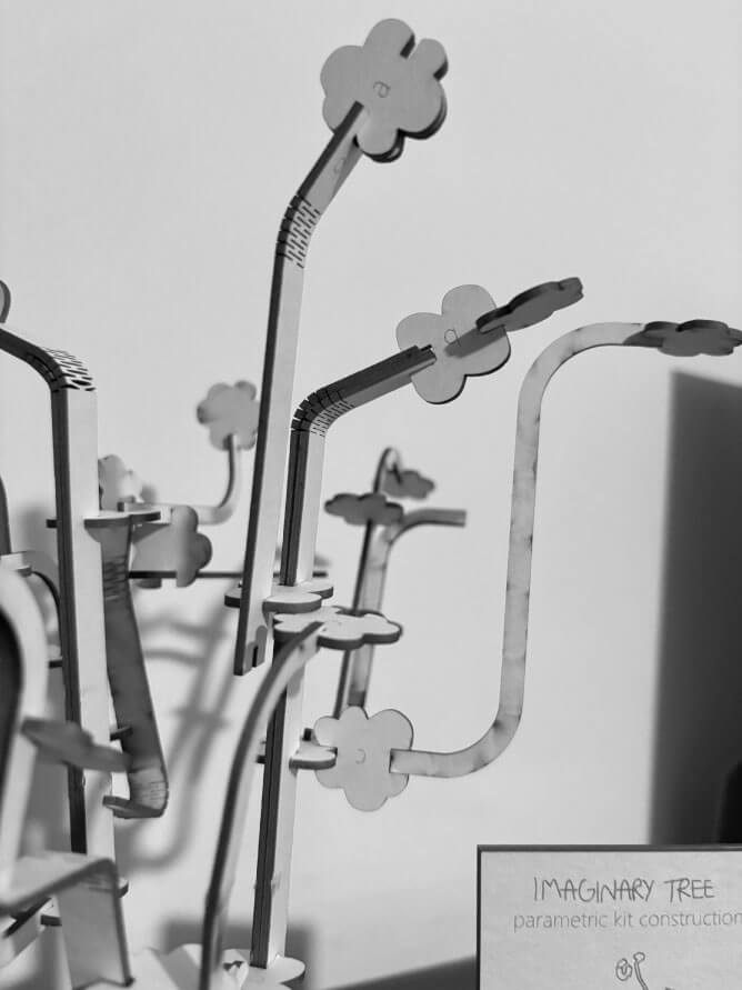
I M A G I N A R Y T R E E
A parametric construction kit for an unlimited imaginary tree.
t h e p r o c e s s
From my cyanotypes drawings I got to the idea of making my imaginary city. First I wanted to make a construction kit by buildings, drawing different facades an joining them but the idea got me stuck in boxes. So looking at my drawings of cities,I decided to keep the nature of the city with very organic an unusual kind of shapes we are used to see for plants and make this parametric tree kit.

idea sketches from my cyanotypes vectors
p a r a m e t r i c D e s i g n
I wanted to follow the logic behind fractal geometry following the growth of a tree. As an infinie puzzle. A fractal is a geometric pattern that repeats itself under several levels of magnification, which appears in various structures and phenomena in nature. ScienceDDirect.com
However my fractal will have to be different. Because I didn't want something so symetrical. Each braches will grow from anywhere yo want to start the tree. So I made a quick change in a fractal in Grasshopper to understand myself how random will the branches grow.
Key parameters:
Add a random domain. For the base point of each branch to grow.
Evaluate curve. To connect the Random as a parameter to change the curves.
Rotate. I had to rotate and make two random domains. For the angle of rotation in X of each branch , and for the lenght.
INDIVIDUAL ASSIGNMENT
v i n y l c u t t e r
The vynil cutter in the lab is the Silouette CAMEO
I had used this machine in the CEFADI team in 2019 when I was in second year of undergraduate, where we made some masks in thin cardboard to see how we can make it fold exaclty where we wanted.
2019 tests in vynil cutter with thin cardboard
vynil s t r o k e s
Vectors from my drawing
I wanted to cut the stokes of the digital drawing from my cyanotypes. So, I quickly got them on Inkscape. Here I got to adjust some figures by editing the umbral of the strokes to be more detailed or thinner. I select the less thinner so I can get more stroke area.
vynil p r o c e s s
Cameo vynilcutter connected to the lab laptop
I had to select just one part of the entire stoke because the base of our vynil cutter was damaged and we had to improvise a new base. I put thick acetate from recomendation of the instructors and manually cut it. At first It looked like it wasn't thick enough as the original base because once it was charged it moved if the drawing was to small, since the the nozzle had to move a lot and very fast.
Spray the acetate
Paste the vynil
Insert it in the vynilcutter
Then to manage the strokes to the vynilcutter I had to download Silhoutestudioto center the image in the machine and select the material and speed of cut:
Import the strokes in .dxf
Material: in this case glossy vynil
To cut and the blase depth in this case 3.
The power and speed as the laser cutter. Here I didnt change the default settings since it is vynil.
Finally stick the material in the base and charge the material.
Adjust the material
Speed and precision
I had to select just one part of the entire stoke because the base of our vynil cutter was damaged and we had to improvise a new base. I put thick acetate from recomendation of the instructors and manually cut it.
At first It looked like it wasn't thick enough as the original base because once it was charged it moved if the drawing was to small, since the the nozzle had to move a lot and very fast.
Cameo vynilcutter connected to the lab laptop
Still I tried and finally I got that small sticker in my phone case.
I only managed to cut some strokes and my name. However the big ones went wrong since I send another work smaller but didn't change the placement and cut over the one that went right. But I still got cool strokes from my drawing and my name in my laptop.
Transfer sticking process
Spray the acetate
Paste the vynil
Insert it in the vynilcutter
Import the strokes in .dxf
Adjust the material
Speed and precision
I had to select just one part of the entire stoke because the base of our vynil cutter was damaged and we had to improvise a new base. I put thick acetate from recomendation of the instructors and manually cut it.
At first It looked like it wasn't thick enough as the original base because once it was charged it moved if the drawing was to small, since the the nozzle had to move a lot and very fast.
I only managed to cut some strokes and my name. However the big ones went wrong since I send another work smaller but didn't change the placement and cut over the one that went right. But I still got cool strokes from my drawing and my name in my laptop.
p a r a m e t r i c C o n s t r u c t i o n K I T
I M A G I N A R Y T R E E
A parametric construction kit for an unlimited imaginary tree.
t h e p r o c e s s
From my cyanotypes drawings I got to the idea of making my imaginary city. First I wanted to make a construction kit by buildings, drawing different facades an joining them but the idea got me stuck in boxes. So looking at my drawings of cities,I decided to keep the nature of the city with very organic an unusual kind of shapes we are used to see for plants and make this parametric tree kit.
idea sketches from my cyanotypes vectors
p a r a m e t r i c D e s i g n
I wanted to follow the logic behind fractal geometry following the growth of a tree. As an infinie puzzle. A fractal is a geometric pattern that repeats itself under several levels of magnification, which appears in various structures and phenomena in nature. ScienceDDirect.com
However my fractal will have to be different. Because I didn't want something so symetrical. Each braches will grow from anywhere yo want to start the tree. So I made a quick change in a fractal in Grasshopper to understand myself how random will the branches grow.
Key parameters:
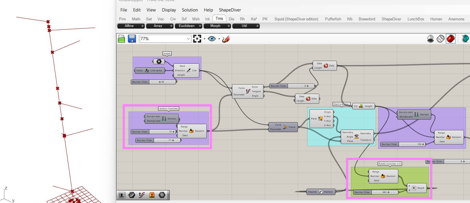
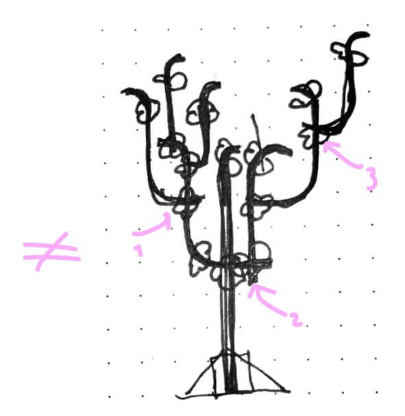
Grasshopper parameter result from a -random fractal branches growth:
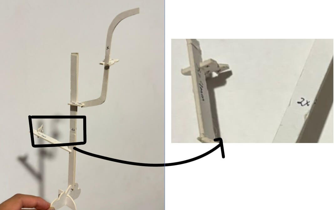
manual model
To understand how the pieces would assembly following the thickness of the material I had to make a draft manually to identify how each joint will depend on the thickness.
p a r a m e t r i c J o i n t s
I did the parametric joints in FreeCAD with spreadsheets and just one reference on the thickness. So if I changed the material everything changes but not only the thickness of the holes but also the scale of all.

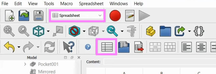
Select the spreadsheets option
Afterdrawing the vector lines of the pieces I selected the spreadsheets option to make the holes of the joints parametric. So I will only have to change the thickness value.
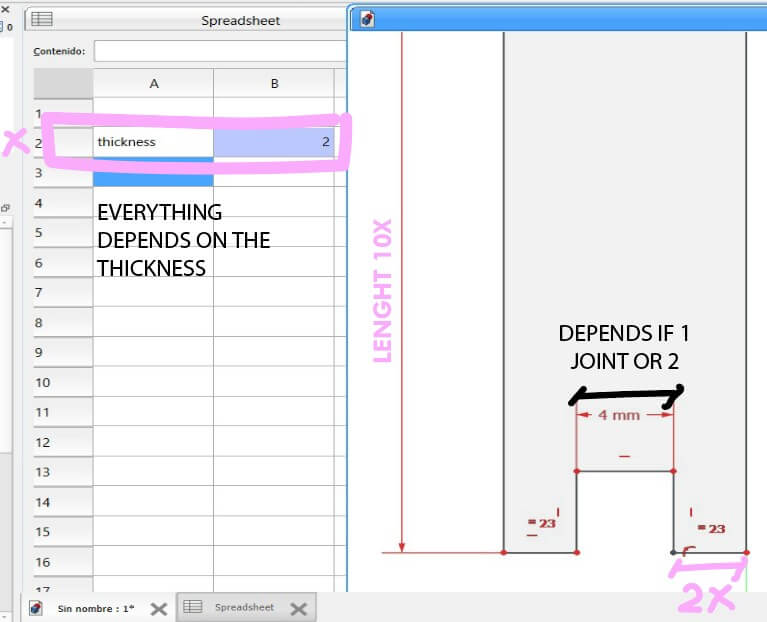
For example the lenght will be 10 times the thickness, and some joints of branches will be of 2 or 1 time the thickness.
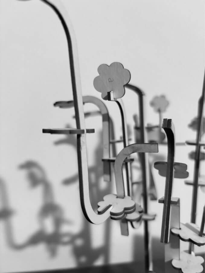
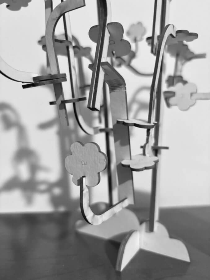
p i e c e s and a s s e m b l y
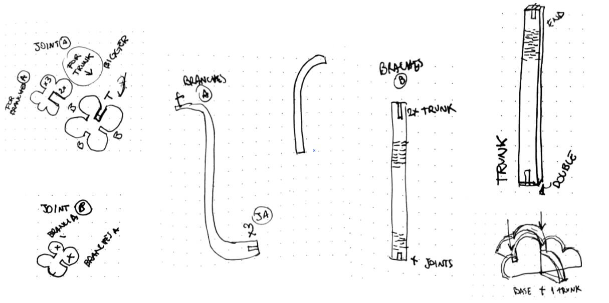
sketches to understand the pieces
For the tree I will nedd a base, a trunk, branches and flowers. Being the flowers some extra joints to have branches in more than 2 axes. And some branches will be flat and others curves with a flexible pattern.
m a t e r i a l
From the group material test I decided to use white cardboard. I use a toleranceof 1.65mm instead of 2mm. I changed the value on freecad and export the pieces in .DXF format.
To export the drawing to the lasercut I had to open the file in Illustrator It is very important to remember to separate on another layer the lines to cut from the engraving. Also the thickness of the line is key for the machine to identify. It has to be 0.001 of stroke for cut.
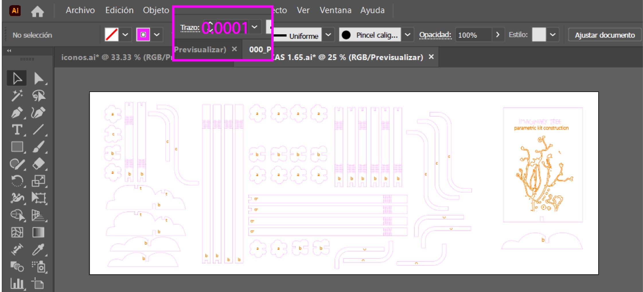
. dxf pieces
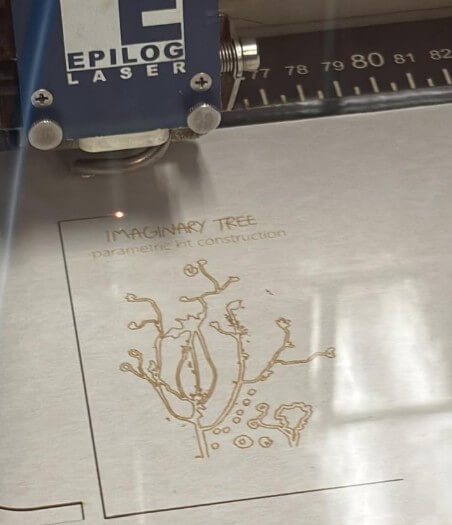
lasercut Epilog Laser Fusion M2 of 30 Watts
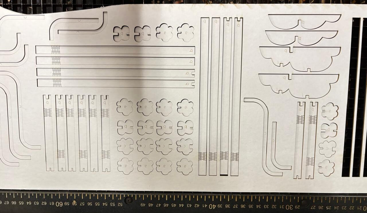
a s s e m b l y
construction process
f i n a l R e s u l t