Week 15 - System Integration
INDIVIDUAL ASSIGNMENT
• Design and document the system integration for your final project
Overview
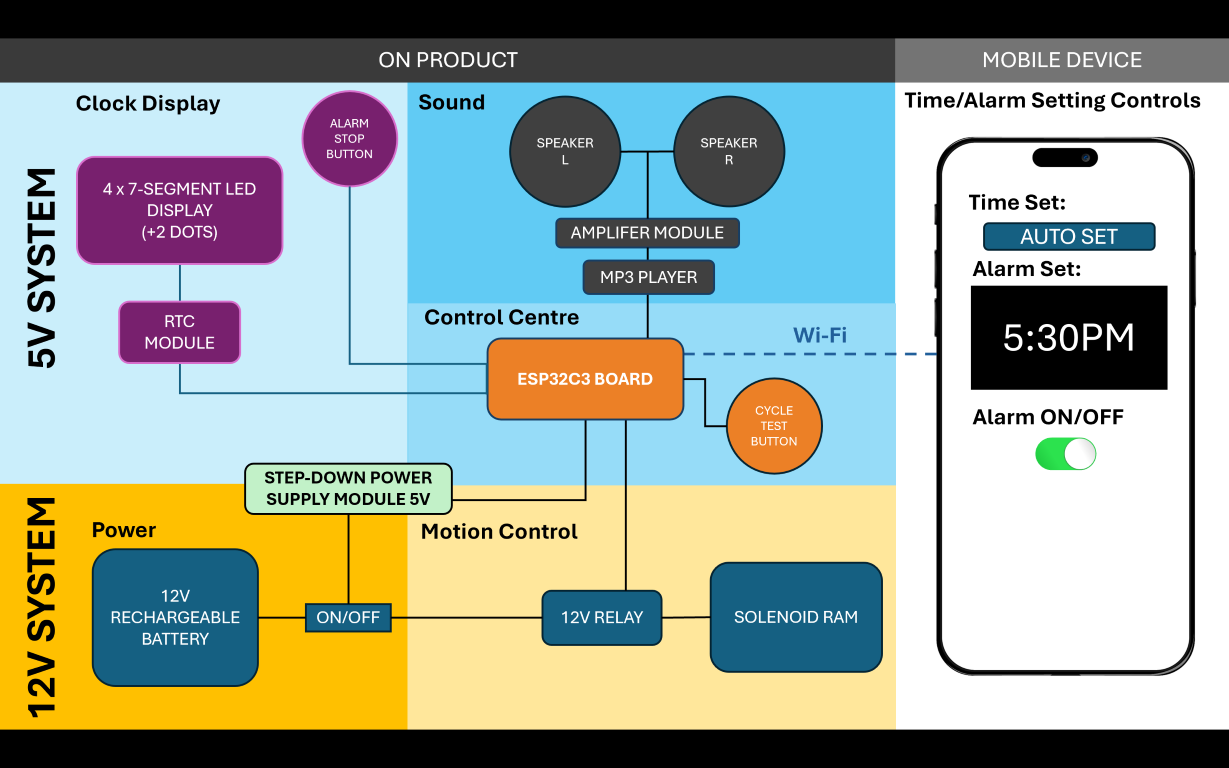
This week’s assignment is to document the system integration for my Final Project. The first thing I need is a System Diagram that will provide an idea of the different systems and components required to realize my Final Project. As shown in my System Diagram above, my Final Project has the following sections:
ON PRODUCT - 5V SYSTEM
ON PRODUCT - 12V SYSTEM
MOBILE DEVICE
I also need to have sections for other things such as:
SYSTEM INTEGRATION
Here, I document the development for different sections of my Final Project in detail.
For a week-by-week chronological update on general progress and development, please visit my Final Project page here.
ON PRODUCT - 5V SYSTEM
Clock Display
I had previously explored making a 7-segment display in Week 10 as shown in the video below.
My experience making this 7-segment prototype revealed some challenges that I will need to address for the Final Project. These are:
- The wires connecting the LED strips between segments are difficult to solder. There are many of them and even if done successfully, it sometimes looks messy, especially around corners.
- Compared to the prototype digit, the digit has to be smaller as I will need to place 4 of them on the project (on one of the roof slopes).
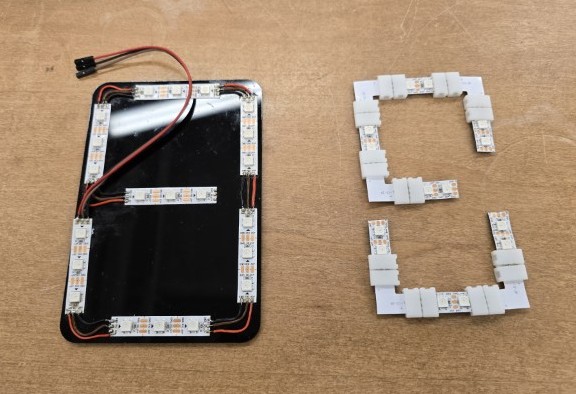
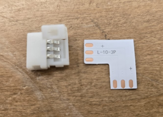
With these in mind, I have currently purchased LED strips with LEDS that are closer to each other. I have also used connectors on some of the corners to reduce the amount of soldering required.
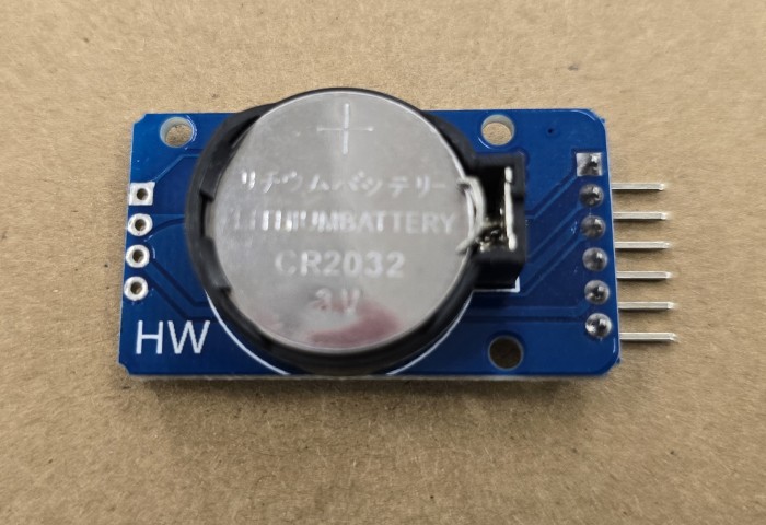
I would also like to introduce an RTC module to the Clock Display so that it is able to keep time even when disconnected from the power supply.
UPDATE: 19 May 2025 – TOO BIG
I tried constructing a single digit to test with my components and it turns out that the off-the-shelf connectors end up adding a lot of size to the digit. A single digit in this configuration means that I can only put 2 digits on the entire clock display panel. I need to fit 4 digits on the clock display panel.
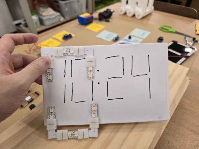
At this point, in my quest to make the digit smaller, I am wondering if I should abandon the idea of using off-the-shelf connectors. I found a compromise which I retain some of the parts but discard the connectors. I will then solder at those connections.
I put this new configuration onto a 3D printed holder and make four of these holders to get a feel of the final size of the clock display panel. This is probably the smallest size I can achieve but it is still about 25% too large compared to my current 3D printed prototype. However, I think I can still get this project to work with some modifications.
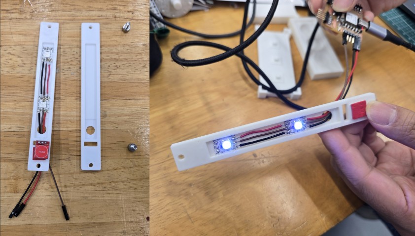
UPDATE: 20 May 2025 – ONE DIGIT
Today, I tried soldering one digit and getting it to work. I succeeded after much frustration and perseverance.
Soldering the LEDs together is certainly easier with the off-the-shelf connectors, but there are still many points to solder. Initially, I tried to rush it, and it did not work out well at all. There were breaks in continuity that were not so easy to rectify. I started again and this time I took it step by step. I checked the continuity after each section to ensure that everything was soldered properly.
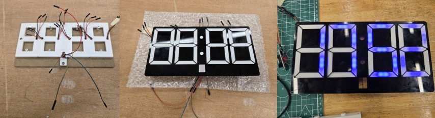
UPDATE: 21to 23 May 2025 – FOUR DIGITS COMPLETE
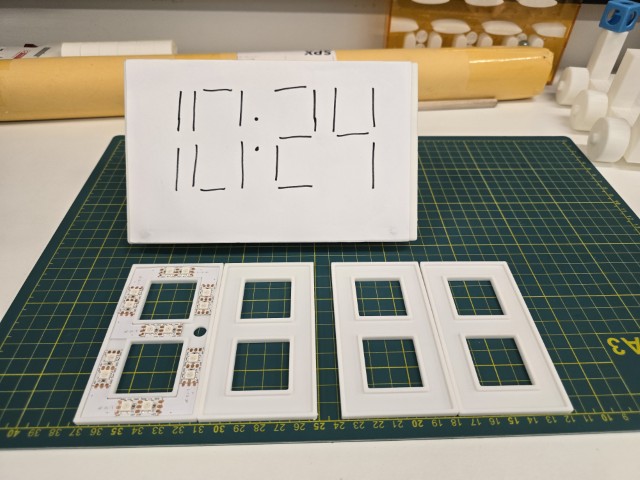
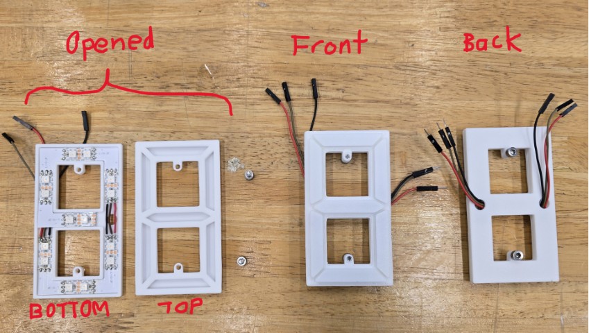
After a few days of work, I completed all four digits as shown in the video below.
Each digit was constructed of:
1. A bottom holder for the Neopixel LEDs
2. A diffuser cover on top
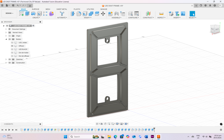
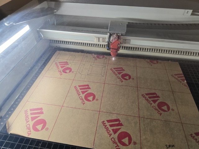
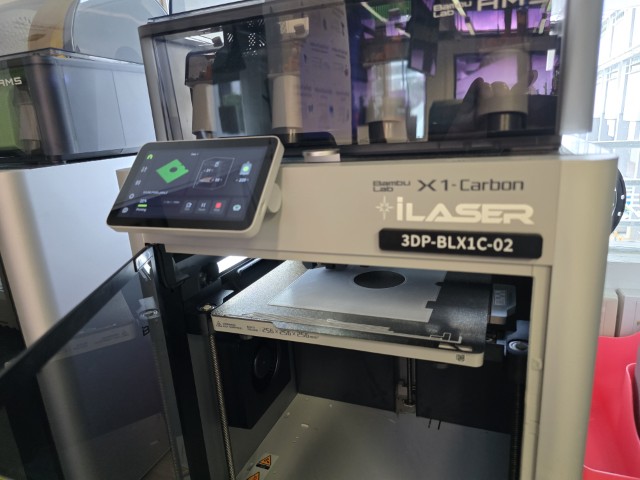
I sketched out the dimensions of each part, created the sketches and 3D models in Fusion 360, and then exported the STLs to be 3D Printed on our lab’s Bambu X1C 3D Printer.
Here is a breakdown of the work I completed during this time:
• Updated the design of the LED housing with a diffuser cover.
• Added feature for top and bottom parts of the LED hosing that can be held together by M4 screws.
• Soldered, assembled and tested all four of the digit modules.
UPDATE: 24to 29 May 2025 – COMPONENTS & PROGRAM TESTED
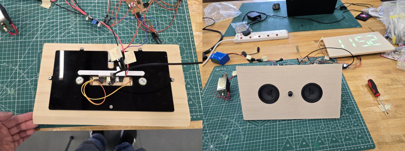
With help from our Fab Lab Alumni, Zi Hon who advised on the program and on how to connect up the components, I managed to get all the components and program in for my Final Project tested. This is a major milestone in my Final Project. Below is a video of the test.
Another thing that I worked on was the 2 dots between the digits that I like to call dot-dot. The construction method is similar to that of the digits.
I also made the black display frame to hold the 4 digits and “dot-dot” together and also to improve readability of the clock display. I laser cut this black frame on our Trotec Speedy 400 laser cutter.
Here is what it looks like.
Summarizing the work I completed during this time:
• Connected up and tested the components and program
• Created the “dot-dot” in between the digits
• Created the black display frame
The design files and programs up till this point are available here.
UPDATE: 30 May to 2 June 2025 – COMPLETED CLOCK DISPLAY PANEL CONSTRUCTION AND COLOUR TEST
While the black display frame was good at holding the digits together, the moment I flipped it over, things started to drop out and misalign. As such, I laser cut a backing to “sandwich” the digits together and hold them together.
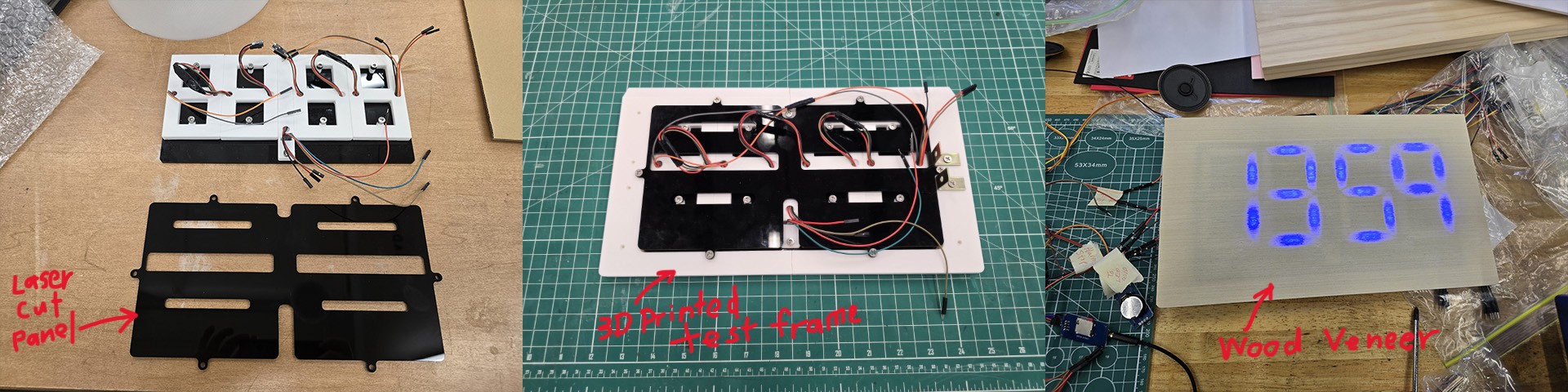
I 3D printed a test frame to check if all the parts fit well together. This will give me confidence that the parts fit well before I mill the wood which will be the final material. I also tested if the LED digits will show up well beneath the wood veneer. I felt that the blue color digits looked quite soft and washed out.
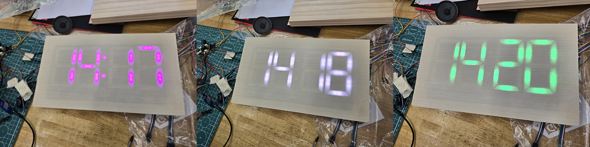
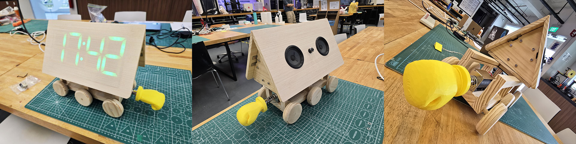
I experimented with some other colors and felt that green is a nice color for the normal clock (the digits turn red when the alarm is activated).
Summarizing the work I completed during this time:
• Completed Clock Display Panel
• Tested clock display with wood veneer effect and different colors
UPDATE: 3 June to 7 June 2025 – FINAL CLOCK DISPLAY PANEL (Construction, ASSEMBLY AND TEST)
These are the last two weeks before the Finals Presentation. Officially, this is the end zone of my Fab Academy journey. After the 3D printed frame was done, I proceed to mill out the wood panel on our STEPCRAFT 420 desktop CNC machine. I finish the panel by filing and sanding and then glue the wood veneer to the wood panel frame. I then put in the four 7-Segment Digits and the Dot-Dot parts, before securing them by screwing in the back acrylic panel.
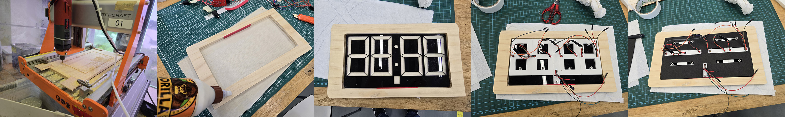
With the Clock Display panel complete, I proceed to connect it to the system and test it. It works!
Summarizing the work I completed during this time:
• Completed milling and assembly of the Clock Display Panel
With the final Clock Display complete, I move onto other sections of the project.
Sound
On the other side of the roof slope, I will place my sound system. I have the following components picked out:
Serial MP3 Player
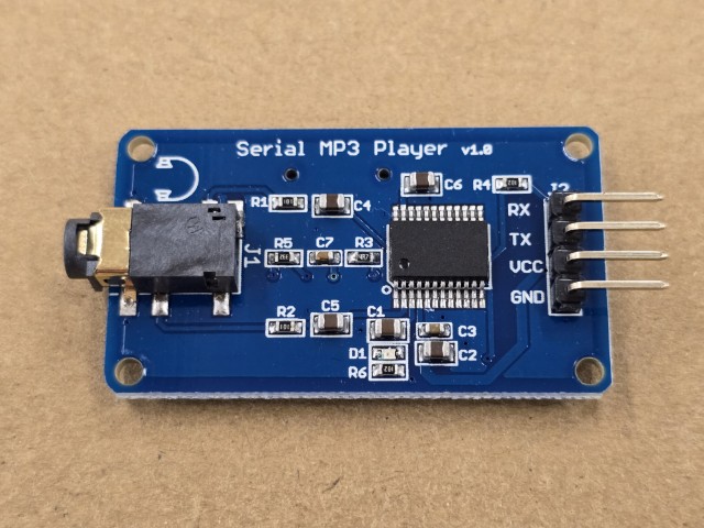
Amplifier module
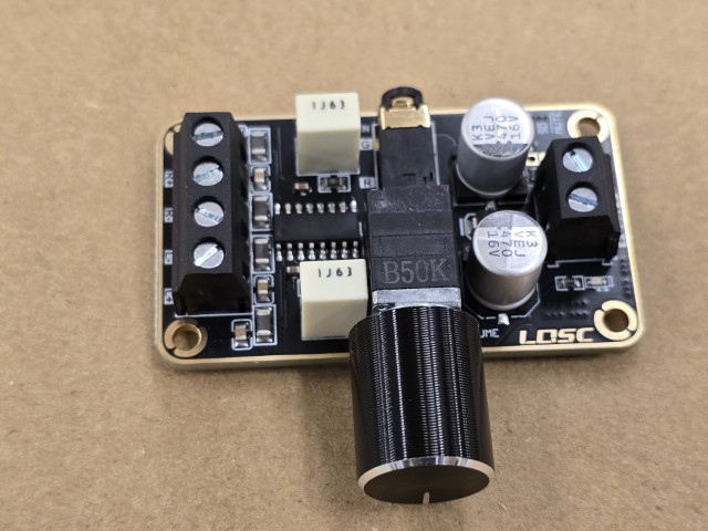
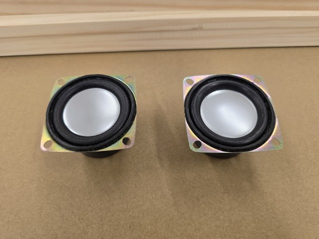
Speakers
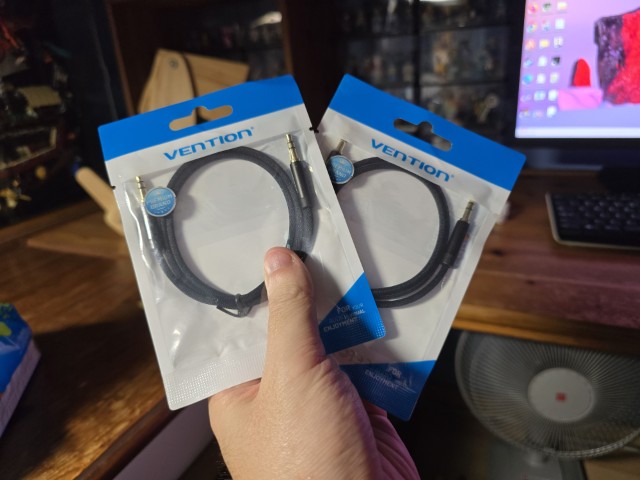
I also have an audio jack cable to connect the Serial MP3 Player with the Amplifier Module.
UPDATE: 3 June to 7 June 2025 – Sound Panel Construction
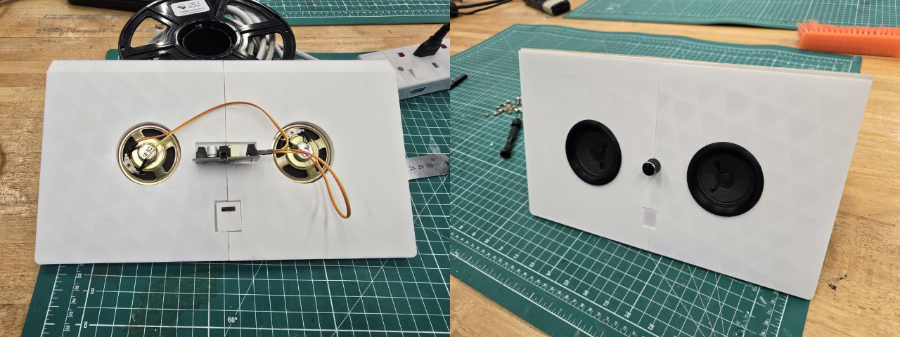
Similar to how I constructed the Clock Display panel, I first decided where each component should go, and then designed a space for it on the panel. I 3D printed a test panel to check the fitting and dimensions.
As the amplifier kept dropping out, I 3D printed a support tray to keep it in place. I also have 3D printed circular rings to hold the speakers in place. You might notice that the speakers used here are different from the ones I originally selected. This is because the original speakers produced a lot of “noise” when first tested. The new speakers are less “noisy” and are thinner.
I discovered some problems when trying to put the Clock Display and Sound panels together. The screw tabs of the laser cut back panels were pushing against each other when assembled, causing a gap at the top of the “roof” that could not be closed.
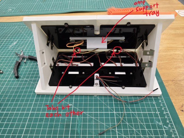
I rectified this by removing the two top screw tabs on the sound panel as shown below.
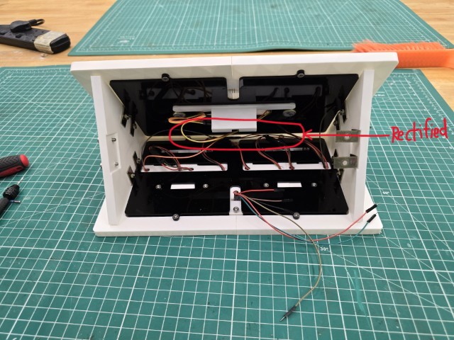
With the design working, I proceed to mill out the panel on our STEPCRAFT 420 desktop CNC machine.
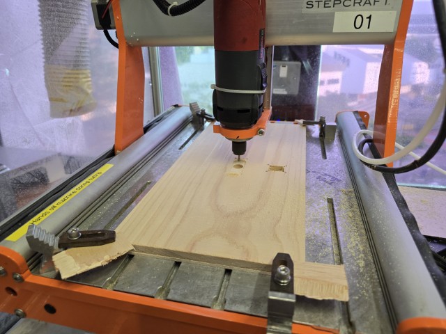
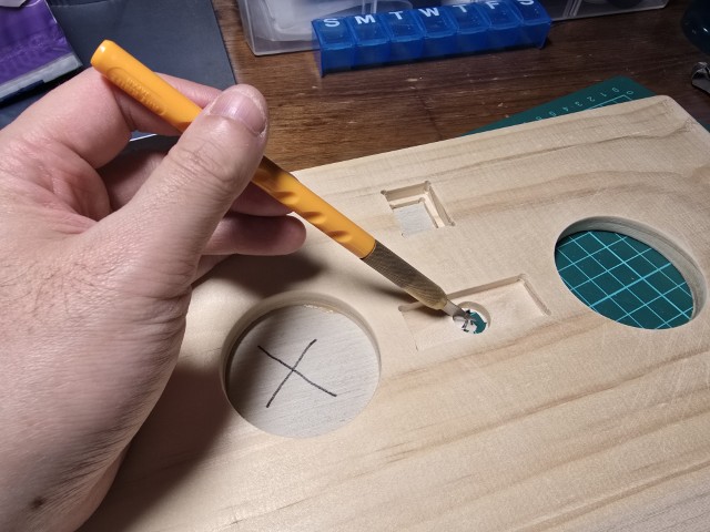
To make it look consistent with the Clock Display panel, I glued the wood veneer to the milled Sound panel. Once glued, I cut out the circular holes for the speakers and the amplifier knob.
Summarizing the work I completed during this time:
• Designed the Sound Panel
• 3D Printed the test frame
• Completed milling the final wood Clock Display Panel
• Glued the wood veneer to the panel
UPDATE: 8 June to 9 June 2025 – Sound Panel Complete
This week is presentation week, and I furiously work towards completing as much as I can. I assemble the sound panel, connect it and test it.
The music is a bit faint in comparison to the solenoid’s (loud) clicking but it works!
Summarizing the work I completed during this time:
• Assembled the final Sound Panel
• Tested the Sound Panel
Control Centre
The Control Centre is the “brains” of the entire project. I am still working on the final board but this current XIAO ESP32C3 board will be sufficient for testing.
UPDATE: 3 June to 7 June 2025 – New Board
As previously mentioned, I already have a board for testing and it works. However, it did not have enough pins for some of the components, and the workaround was to splice some wires to share connections.
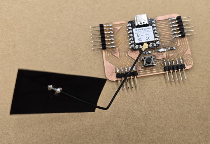
This is why I worked on a new board with pins catered to all the functions of this Final Project. I designed this board so that the pins (more or less) point in the direction of the panel that houses the components (with the Clock Display elements on one side, and the Sound panel/other elements on the other side) as shown below.
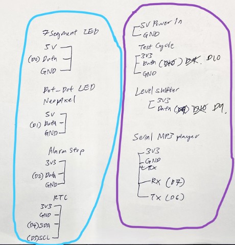
Pinout planning sketch
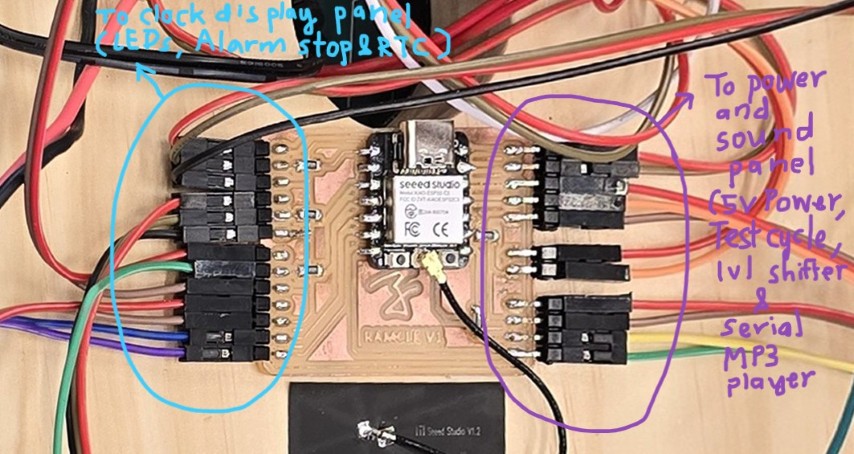
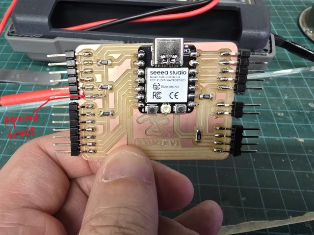
Connected pinout
The process of creating the board is the same as those outlined in Week 6, so I won’t go too much into the process.
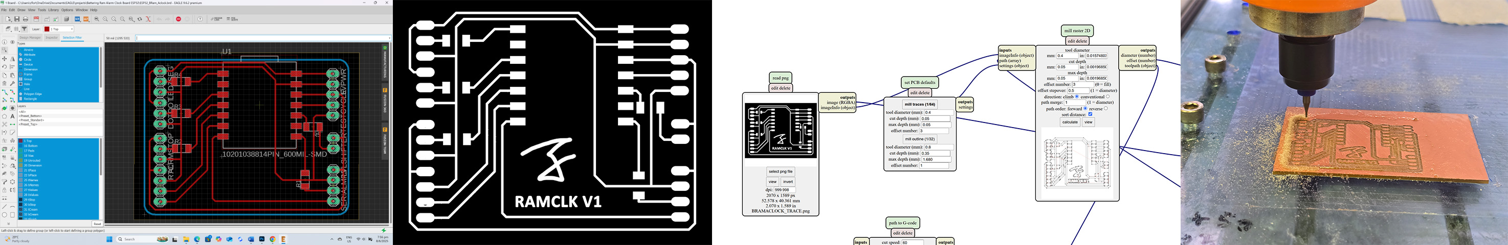
The key difference was that because I needed more sets of pins going to the different components, I laid down a couple of zero-ohm resistors to act as a bridge for the new path to go under. I also accidentally ripped out a trace when soldering, but Fab Lab Alumni, Zi Hon helped me to repair the trace using a wire.
Summarizing the work I completed during this time:
• Designed the board in Eagle
• Milled out the board
• Soldered the components and pins onto the board
UPDATE: 10 June 2025 – Program uploaded onto Final Board
With the construction of the housing complete, I upload the final program onto the new board. Our Fab Lab Alumni, Zi Hon advised and helped me on the program.
The program is sectioned into the following functions:
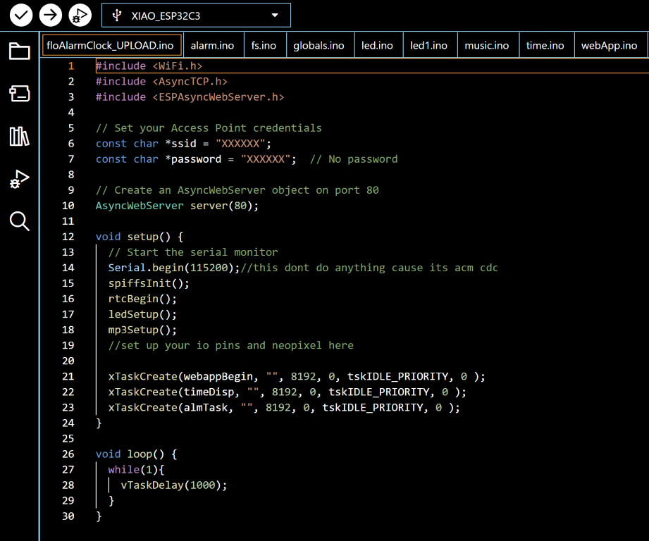
1. floAlarmClock.ino – This is the main setup and loop of my ESP32-based project. It uses FreeRTOS tasks and sets up a web server over Wi-Fi, for the Battering Ram Alarm Clock project.
Included Libraries
WiFi.h: Connects the ESP32 to a Wi-Fi network .
AsyncTCP.h and ESPAsyncWebServer.h: Allow for asynchronous web server functionality.
Wi-Fi Setup
const char *ssid = "XXXXXX";
const char *password = " XXXXXX ";
This is to set up the Wi-Fi connection.
Web Server
AsyncWebServer server(80);
Creates a web server object that listens on port 80 (default HTTP port).
Main Functions
spiffsInit(): Mounts the SPIFFS file system (to serve files from flash memory).
rtcBegin(): Initializes a Real-Time Clock (RTC) chip/module.
ledSetup(): Sets up a NeoPixel LED strip.
mp3Setup(): Prepares an MP3 player
FreeRTOS tasks
Creates 3 FreeRTOS tasks (runs them in parallel):
xTaskCreate(webappBegin, "", 8192, 0, tskIDLE_PRIORITY, 0 ); Starts the web server, routes, and web UI.
xTaskCreate(timeDisp, "", 8192, 0, tskIDLE_PRIORITY, 0 ); Updates LED display with current time.
xTaskCreate(almTask, "", 8192, 0, tskIDLE_PRIORITY, 0 ); Handles the alarm logic.
2. alarm.ino – This is the alarm control logic.
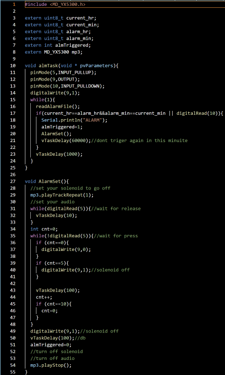
Here is how it works:
ESP32 connects to WiFi and starts web server (floAlarmClock.ino).
almTask runs in background checking:
• If current time == alarm time.
• OR user presses a manual override button.
If triggered:
• Audio track loops using the MP3 module.
• Solenoid turns on to “ram”
• Waits for user to press a button to stop the alarm.
On stop:
• Audio stops, solenoid shuts off, and alarm resets.
3. fs.ino - This code for an ESP32 uses the SPIFFS (SPI Flash File System) to store and retrieve alarm time settings in a text file.
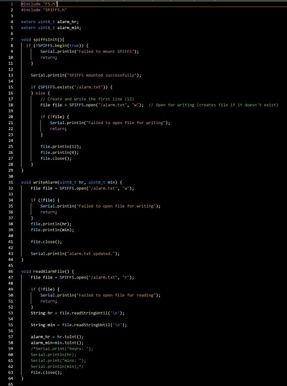
In floAlarmClock.ino, spiffsInit() is called in setup():
This initializes the SPIFFS file system and ensures there's a file (/alarm.txt) storing an initial alarm time.
In the alarm.ino, readAlarmFile() is used in almTask():
This reads the alarm time from SPIFFS and updates the variables alarm_hr and alarm_min used in the alarm logic.
This file-handling code is the backend for alarm time management, enabling the ESP32 to:
• Remember the alarm time across reboots
• Load the alarm time before checking if it matches the current time
4. globals.ino - This snippet declares and initializes some global variables used for managing time and alarm state.
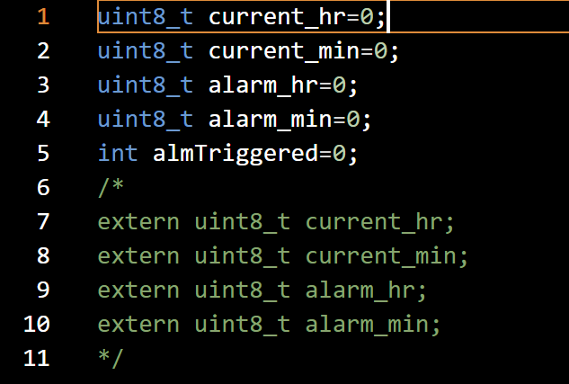
| Variable | Purpose |
|---|---|
| current_hr | Current hour (from RTC or internal clock) |
| current_min | Current minute |
| alarm_hr | Set alarm hour (read from SPIFFS) |
| alarm_min | Set alarm minute (read from SPIFFS) |
| almTriggered | Boolean flag (0/1) indicating alarm state |
5. led.ino – Controls the Neopixel display on the 7-segment digits. This code defines which segments of Neopixel LEDs to light up so that they can form a coherent display. Uses the Adafruit_NeoPixel,h library.
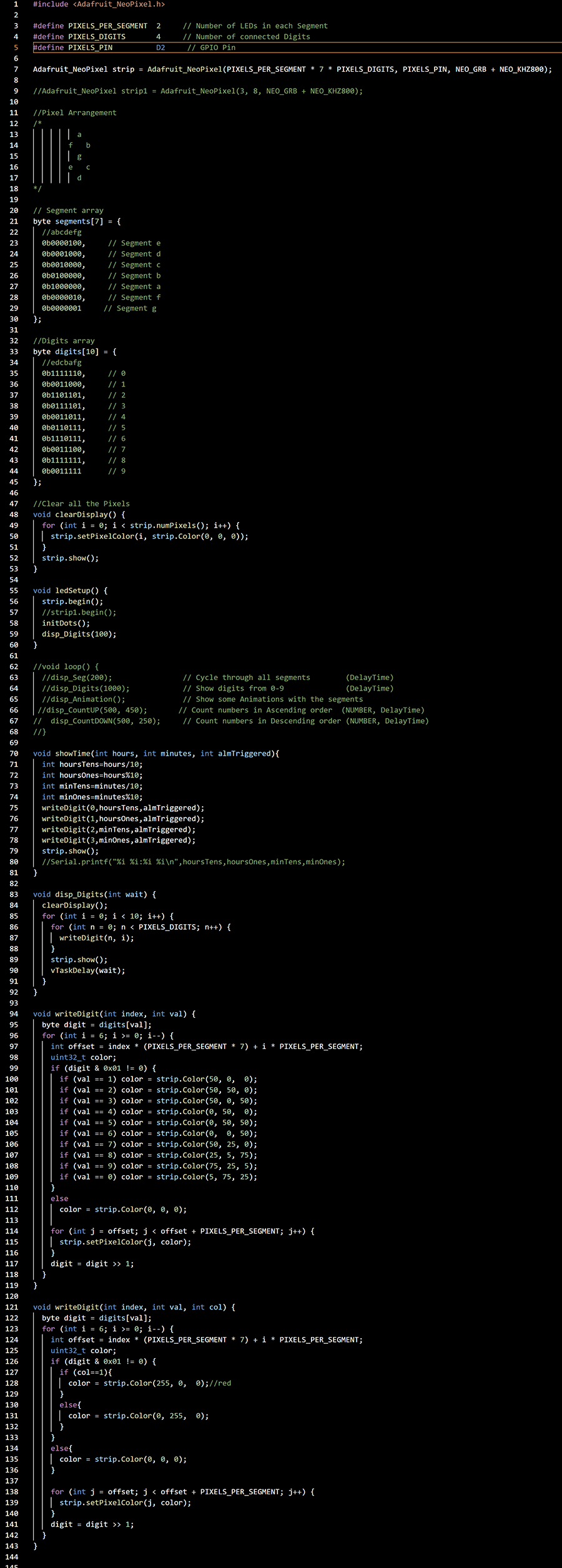
NeoPixel Setup
#define PIXELS_PER_SEGMENT 2 // 2 LEDs per segment
#define PIXELS_DIGITS 4 // 4 digits (HH:MM)
#define PIXELS_PIN D2 // Output pin (D2 = GPIO)
Each digit has 7 segments, each segment has 2 LEDs. Total LEDs = 2 * 7 * 4 = 56
Adafruit_NeoPixel strip = Adafruit_NeoPixel(...);
Initializes the NeoPixel strip.
Digit and Segment Mapping
// 7 segments: a-g mapped by bits in a byte
// Each number 0-9 is defined using these 7 segments
This is the standard way to encode digits for 7-segment displays.
clearDisplay()
Turns off all pixels.
ledSetup()
Called once during setup(), this function:
• Begins NeoPixel communication
• Initializes "dots"
• Displays a default animation
showTime(hours, minutes, almTriggered)
Called in timeDisp() task to:
• Break hours and minutes into 4 digits
• Call writeDigit() four times
• Show green digits if normal, red if alarm is triggered
writeDigit(index, val, col)
This version of writeDigit lights up the digit at a specific index with a specified value (val, 0–9), and colors it based on col:
• If col == 1 → alarm active → red
• Else → green
Each digit uses:
index * (PIXELS_PER_SEGMENT * 7) + segmentOffset to calculate the right LED positions.
disp_Digits(wait)
This is a simple test loop to cycle through 0–9 across all digits (can be used for testing).
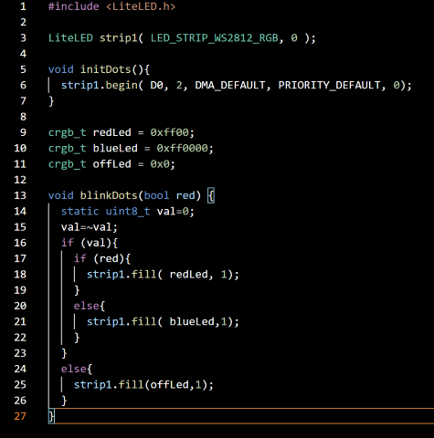
6. led1.ino – Controls the 2 dots (dot-dot) between the clock’s 7-segment digits. This code snippet adds a blinking colon (dots) effect to my NeoPixel-based clock using the LiteLED library. I had to use another library (LiteLED.h) to control the LEDs because there were conflict issues with the Adafruit_NeoPixel.h library when trying to control a second LED strip.
7. music.ino – Controls the serial mp3 player. Essentially, when the alarm from alarm.ino is triggered, the MP3 module play tracks from a microSD card.
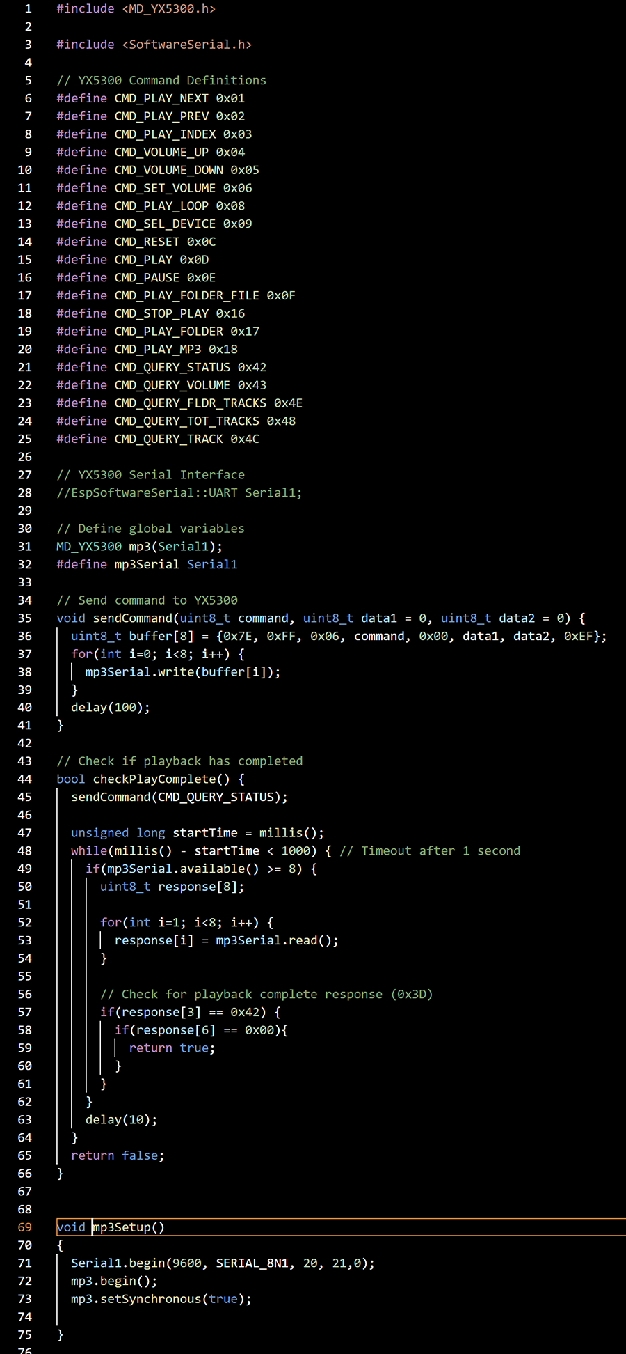
8. time.ino - This code integrates an RTC (Real-Time Clock) — specifically a DS3231 module over I²C — into my project.
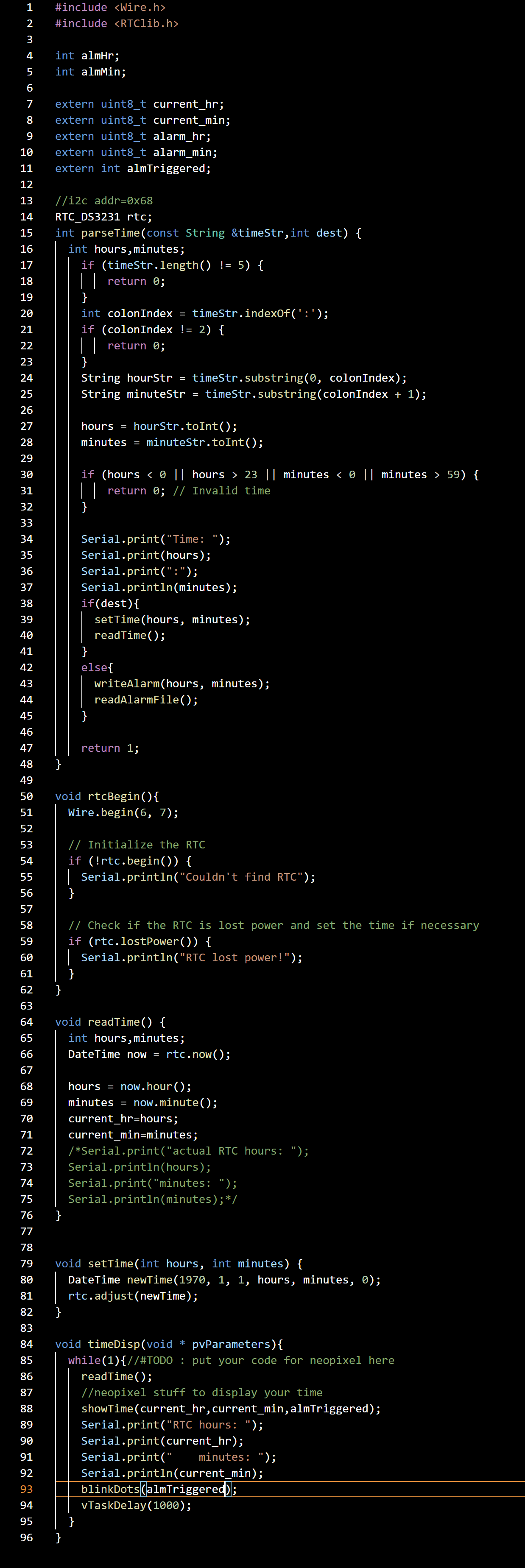
Here is a summary of the code components.
| Component | Role |
|---|---|
| rtcBegin() | Initializes the DS3231 RTC hardware on startup |
| readTime() | Updates current_hr and current_min from RTC |
| setTime() | Adjusts RTC to a new time |
| parseTime() | Parses a string "HH:MM" and either sets RTC time or alarm |
| timeDisp() | Runs as a task, updates display + global time every second |
| almTask() (from before) | Uses current_hr/min to check if alarm should go off |
| writeAlarm() / readAlarmFile() | Stores/loads alarm time in SPIFFS |
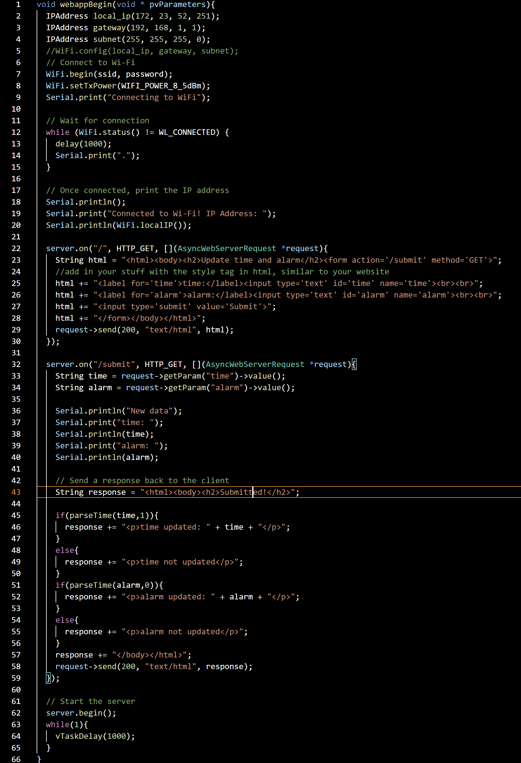
9. webApp.ino - This code defines a FreeRTOS task (webappBegin) that launches a simple web interface on an ESP32 using the ESPAsyncWebServer library. It allows the user to:
• Connect the ESP32 to Wi-Fi.
• Host a web page to view and set time and alarm values.
• Call the parseTime() function to apply submitted values (either set the RTC time or save alarm to SPIFFS).
The program files are available here.
With the Program uploaded to the final board (tested and working), I can mark this section as complete and move onto other sections of the project.
ON PRODUCT - 12V SYSTEM
Power
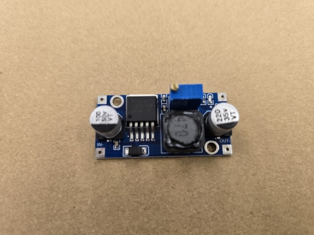
My project is powered by a 12V rechargeable battery that powers the 12V Solenoid ram, with a module to step down to 5V for the other parts of the system operating at 5 Volts.
12V Battery
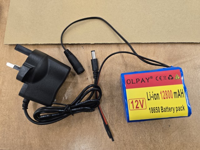
Step-down Module
UPDATE: 10 June 2025 – Prism Base Board Complete
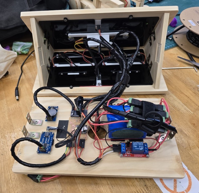
As part of finishing the systems integration of the project. I secured the components in this section (12V Battery, Step-down Module) to the base board. The image below shows the base board before and after the components were secured.
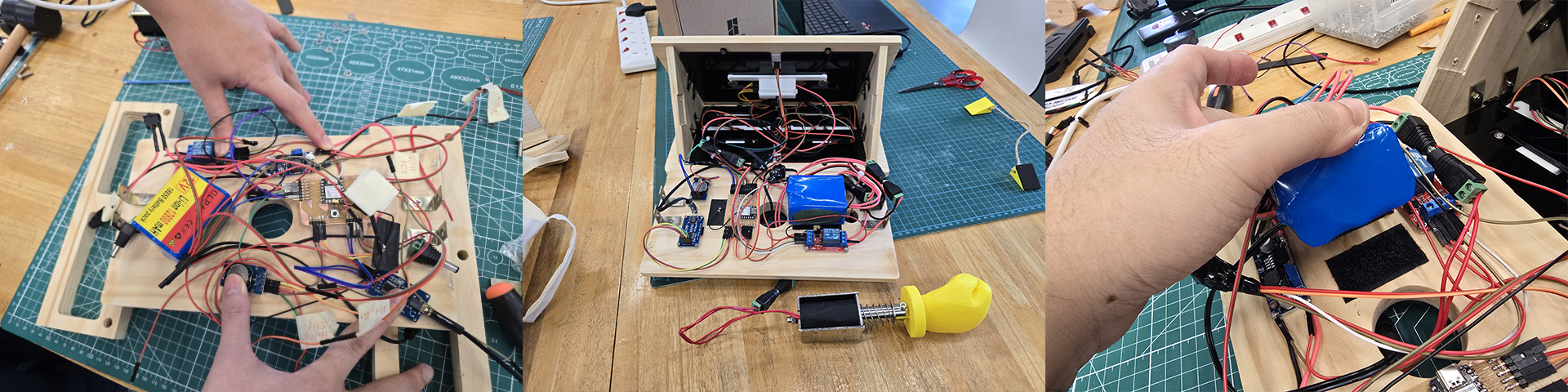
I used Velcro to secure the battery pack, and for the other parts, I screwed them down directly onto the prism base board.
Summarizing the work I completed during this time:
• Secured all the battery using Velcro to the prism base board
• Secured the buck converter (Step-down Module) onto the base board
With the components of this section secured to the prism base board, I can mark this section as complete and move onto other sections of the project.
Motion Control
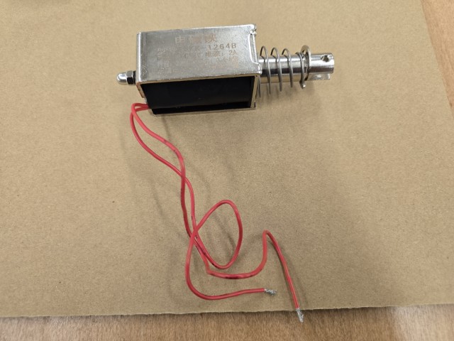
The only thing that is intended to move is the solenoid ram. For this, I have a 12V solenoid operating at 2A current.
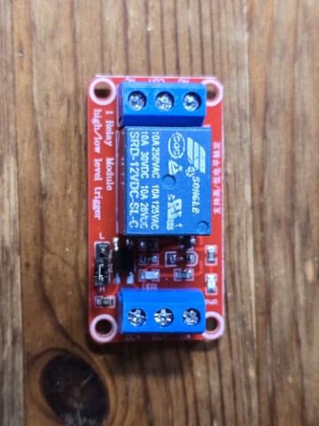
I also require a relay for the 12V solenoid to receive 5V signals from the ESP32 board.
UPDATE: 10 June 2025 – Motion Control Complete
The motion control was already working in a previous test as shown in the video below.
Since the solenoid ram was already working, all I needed to do was to secure it to the body of the Battering Ram Alarm Clock.
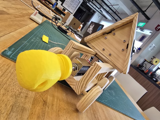
I also attached a 3D printed boxing glove to make the Battering Ram Alarm Clock look more fun. The original boxing glove model is remixed from Thingiverse (License: CC BY-SA - Creative Commons - Attribution - Share Alike license) by Gromozekaa. I modelled an adapter in Fusion 360 to connect the boxing glove to the solenoid.
MOBILE DEVICE
Time/Alarm Setting Controls
After discussing with my colleague (and Fab Academy graduate) Louis, I decided to reduce the number of buttons on the clock as I can have some of these functions on a mobile device. This reduces visual clutter and also reduces the number of interactive buttons that I need to connect to the physical system.
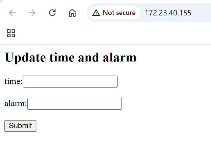
UPDATE: 11 June 2025 – Time-setting via Wi-Fi
With the program I from the earlier section (Under Control Centre), I am able to set the time as well as the alarm via a simple web interface through Wi-Fi connection. Once set, the RTC module keeps the time even if the power is momentarily disconnected.
OTHERS
Structure/Housing
I first started on the body of the Battering Ram Alarm Clock in Week 02. Since then, I have 3D printed that model out (in Week 06) to look at it almost every day and to get a good sense of the project.
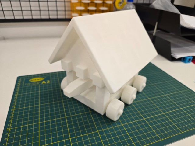
While this model was a good size, I was annoyed by how the top part came apart from the base so easily since it was only “blu tacked” together. I have since worked on an improved version where I have included sliding rails at where the top part should join with the base.
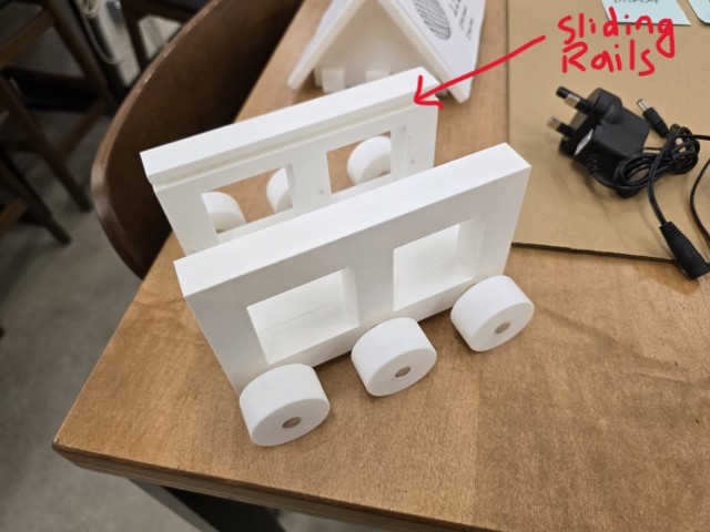
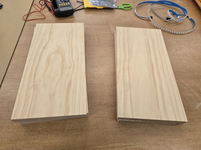
Admittedly, there is still a lot of work to be done on the top part (the prism) and this is where I am at right now. Also, from the beginning, I have always wanted to finish this project in wood, which I have already purchased some furniture-grade pine wood to machine on the CNC.
UPDATE: 11 June 2025 – Final Design
For the Final Design, I used Fusion 360 to model the different parts of the structure/body.
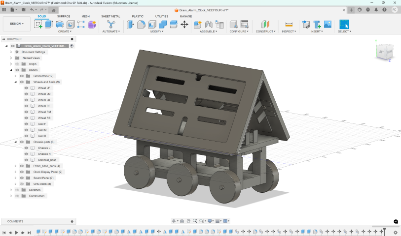
I then followed up by 3D printing a test prototype to assess how well the design will work and fit the components. The design is such that the top prism is connected to the lower chassis by a sliding rail. This means that the orientation of the “roof” is reversible.
Once the 3D printed parts were tested, I proceeded to CNC mill them out of the pine wood material. Working this way helped to minimize mistakes before milling on the final material.
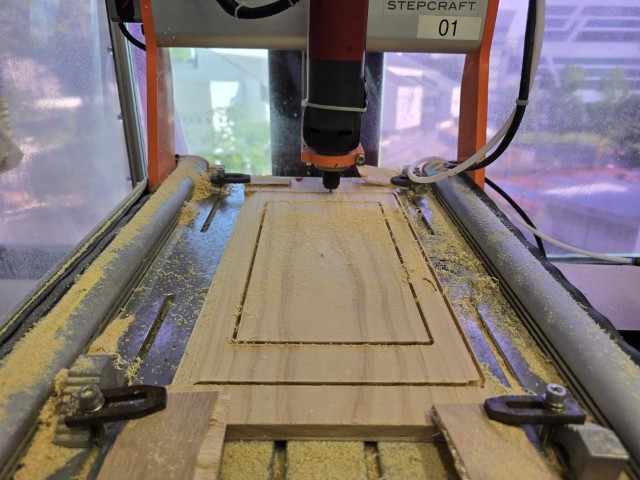
This is the result.
Assembly and Integration
UPDATE: 11 June 2025 – Final Design
I housed most of the components inside the prism core of the Battering Ram Alarm Clock. The only component outside of the prism is the solenoid ram. Here is a breakdown of where each component is placed:
| Location | Component/s |
|---|---|
| Clock Display Panel | 1. LEDS 2. Alarm stop button |
| Sound Panel | 1. Speakers 2. Amplifier 3. Test cycle button |
| Prism Base Board | 1. ESP32-C3 board 2. RTC module 3. Battery 4. Step-down module 5. Relay 6. Serial MP3 player 7. On/Off switch |
| Lower Chassis | 1. Solenoid |
For the Prism base board, I secured most of the components to the base board directly using M2 or M3 screws (depending on the holes provided on the component). I had to be careful not to short the RTC module with the screw, so I created a 3D printed spacer to solve the issue.
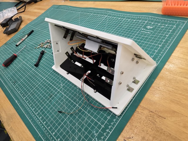
Below is a sequence of images showing how I assembled my project.
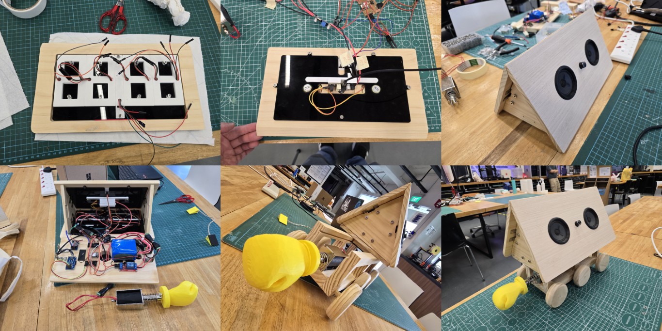
I also tidied up the wiring as shown below. I bundled the wires together neatly to avoid a spaghetti mess.
Bill-of-materials (BOM)
Below is the BOM for my project:
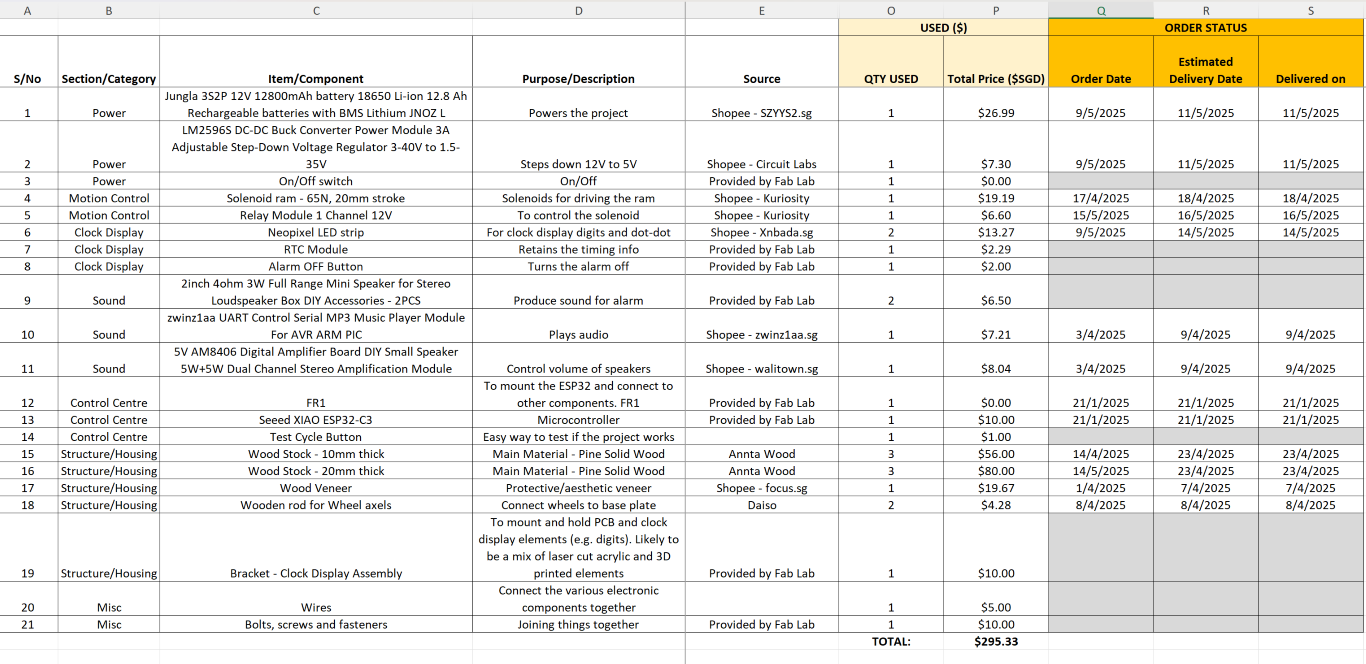
The biggest cost of materials are the wooden pine boards that that purchased. All the main components have arrived.
SCHEDULE
My schedule is as follows:
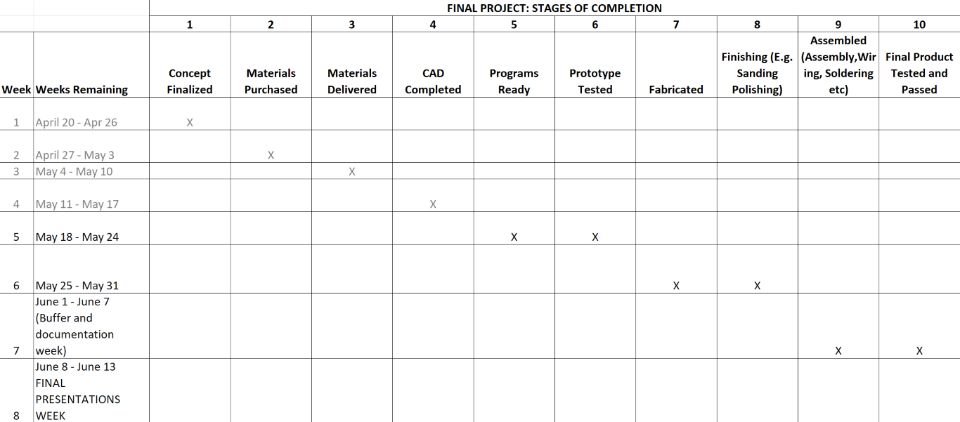
It consists of 10 stages of completion. I recently had all my materials delivered which means I am at Stage 3 now (as of 17th May 2025). It is getting packed as we moved towards the deadline.
This concludes this week’s assignment.