Week 10 - Output Devices

Group assignment:
• Measure the power consumption of an output device.
• Document your work on the group work page and reflect on your individual page what you learned.
Individual assignment:
• Add an output device to a microcontroller board you've designed and program it to do something.
Group assignment
For this week’s Group assignment, I teamed up with my fellow Fab Academy buddy Haw Ren to measure the power consumption of a NeoPixel strip and a DC Motor.
The documentation for our Group assignment can be found here.
Group assignment reflection
This week’s group assignment is quite straightforward. It is not difficult to measure the power consumption of an output device with the tools such as the USB meter. My takeaways for this week’s group assignment are:
1. When using the USB meter, consider the entire circuit, not just the output device. When measuring the power consumption of the NeoPixel strip, we initially neglected to account for our XIAO RP2040 board which also draws power. It is something that can be easily overlooked when using a USB meter.
2. While measuring the power consumption of the DC Motor, we used a bench power supply that has a current limiting function. This led to some unexpected results (the current was expected to rise but instead, the current remained stable, and the voltage dropped) that we had to turn to ChatGPT for clarification.
Individual assignment
Overview
This week, I attempt to make a 7-segment display and get it to display the numbers 0 to 9. Why? This is because I am making a Battering Ram Alarm Clock for my Final Project, and knowing how to make and control a 7-segment display will help me understand how to make an essential piece of my Final Project – The clock display.
Making the 7-segment display
Why not buy a 7-segment display you ask? Well, those available in the market are either too big or too small for what I want to have in my Final Project and so, I explored making my own.
To start, I watched this YouTube video GIANT 3D PRINTED LED CLOCK by Ivan Miranda.
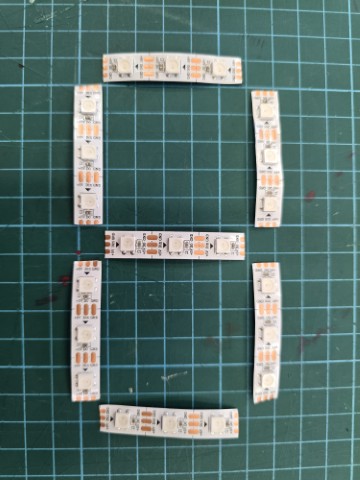
This gave me a good idea of what I needed to make my own 7-segment display. I started by cutting out 7 NeoPixel strips of which each segment has 3 LEDs on it.

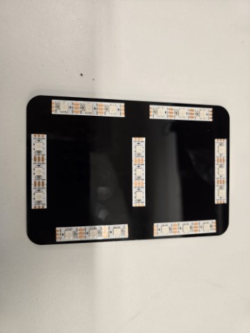
I then use the xTool P2 laser cutter to cut out a simple base (black acrylic) to paste the NeoPixel strips on. This is the same laser cutter that I had used in week 03's assignment.

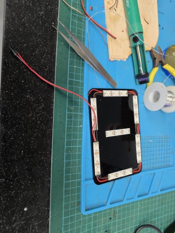
The NeoPixel strip segments must be laid out in the correct alignment to ensure that the segments can be wired together in a continuous path. Once mounted correctly, I can now proceed to solder the wires to join the 7-segments together.

It was a simple (albeit a little tedious) process to solder all the wires on and after a few hours, I have soldered the wires to the LED segments and I have my 7-segment display. Now I just need a program to light it up and display numbers. Programming and Testing I knew that I needed a program to show numbers on my 7-segment display. For this, I looked at 2 internet sources:
Setup
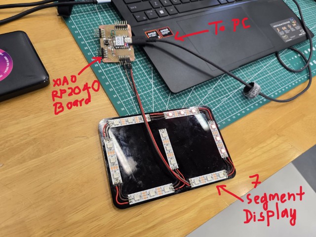
I connect the 7-Segment display to my XIAO RP2040 board, which is in turn connected to my PC.

Now, I am ready to test it.
Test 1
I upload the following program from ArduinoGetStarted.com to my board. This is a relatively easy to understand program as it comes with clear comments. The only things I needed to do was to:
1. Set the signal pin to D10
2. Set the number of LEDs on the NeoPixel strip to 21
And… Only one segment lights up.
I had a feeling that I had messed up the soldering and this was confirmed by my colleague (and Fab Academy graduate) Willie. I had some stray solder causing a short between one of the signal and ground pads. Back to the soldering station for some emergency repairs!
Test 2
After some resoldering, I used the same code on the 7-Segment display and thankfully, it works this time.
Test 3
Now that I ensured that the 7-Segment display is working, my next test will be to get it to display some numbers. I will need numbers for my final project clock so for this test, I use the following code from Intructables.com. The explanation for the code (from ChatGPT) can be found here.
I run the code and while at first it seems to work with the LED animation, it failed to display numbers coherently.
With some help from my Fab Academy Instructor, Steven, I figured out that my NeoPixel strips ran in a different pattern from the code I used, causing it to display gibberish. I adjusted the code to match my 7-Segment display and then ran it again. This time it works!
Reflection
Another electronics week completed and by now, I have gotten used to failing and trying again. I suppose I should expect this as I did not have much experience with electronics or programming. I am however able to understand a little bit more than I did before I started Fab Academy and am happy that I have some progress. I know do not have all the skills and knowledge I need to complete my final project by myself, but with some help from my instructors, I think I can do it.
I came across this message by Steve Bartlett on social media and would like to share this with anyone (present or future) who is similarly struggling with Fab Academy.

Files
This concludes this week’s assignment.
