Week 03 - Computer Controlled Cutting
Group assignment:
• Do your lab's safety training
• Characterize your laser cutter's focus, power, speed, rate, kerf, joint clearance and types.
• Document your work to the group work page and reflect on your individual page what you learned. Individual assignments
• Design, laser cut, and document a parametric construction kit, accounting for the laser cutter kerf, which can be assembled in multiple ways.
• Cut something on the vinyl cutter.
Group assignment
For this week’s Group assignment, I teamed up with my fellow Fab Academy buddy Haw Ren to characterize our laser cutter’s (Universal Laser Systems VLS6.75) focus, power, speed, rate, kerf, joint clearance and types. The documentation for our Group assignment can be accessed here.
Individual assignment - Laser Cutting
This week, the task was to create a parametric construction kit. I chose to do this with the Xtool P2 laser cutter. Here is how I did it: Getting Started After looking for some inspiration on the internet for construction kit toys, I started by sketching out a rough idea of how my kit might possibly look like, the dimensions and how the pieces might connect to each other.
First Prototype
Once I landed on an idea, I moved onto Fusion 360 to create drawings for my first parts. I set up my drawing parametrically (mostly using the “Equal” constraint) so that I will be able to adjust and update the dimensions quickly. I know I will need this feature as I will be tweaking the dimension of the connection between the parts later. Exporting SVG using Shaper Utilities To laser cut, I will need to get an SVG file from Fusion 360. For this, I recommend using this free plug-in from the Autodesk app store. I learned how to use it by watching this short YouTube video by Making Makers.
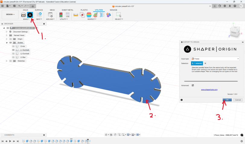
1. Once installed, click on the Shaper Utilities icon
2. Click on the face you want to export as a drawing
3. Click Ok I will then bring the SVG into CorelDraw to do some simple clean up in preparation for the next step.
XTool Creative Space
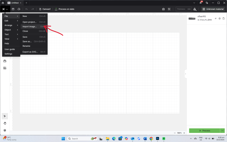
Once I have my SVG file, I can send it to xTool Creative Space which is the software that controls the xTool P2 laser cutter.
1. Open xTool Creative Space
2. Click on New project (Top right green button)
3. Import the SVG into the workspace
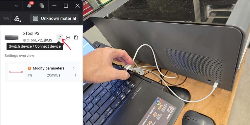
4. Connect to the P2 laser cutter – I connected using the USB cable and then pressing the Switch device/Connect device. Click Connect.
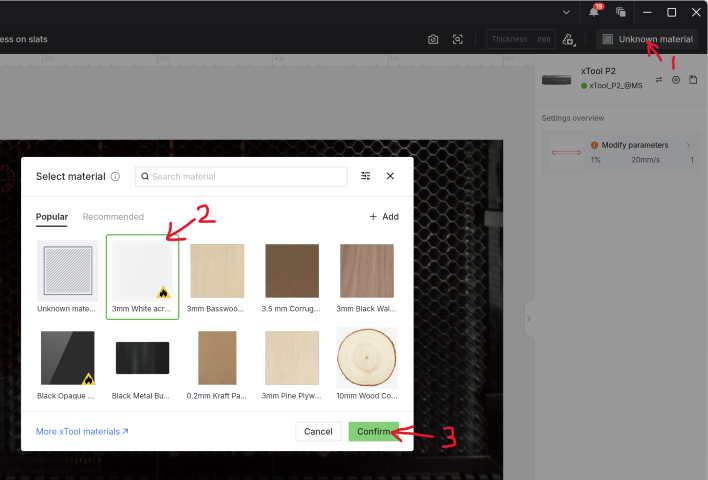
5. Select the material setting and confirm
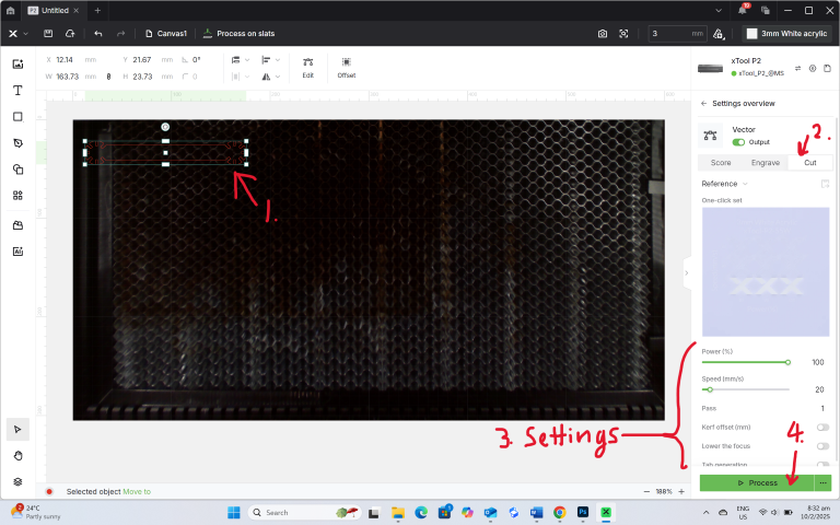
6. Adjust the settings using following these steps:
- Select the outline of the object to cut
- Click on the Cut tab
- Refine the settings - I tried the default setting for acrylic (Power = 100%, Speed = 20) and it did not cut through. I tweaked the setting to cut a bit slower (at the same power setting).
- Click Process
7. Send the job to the P2 to cut – It goes to a new screen that shows the trajectory of the cutting path. Once there, click on Start > OK Process
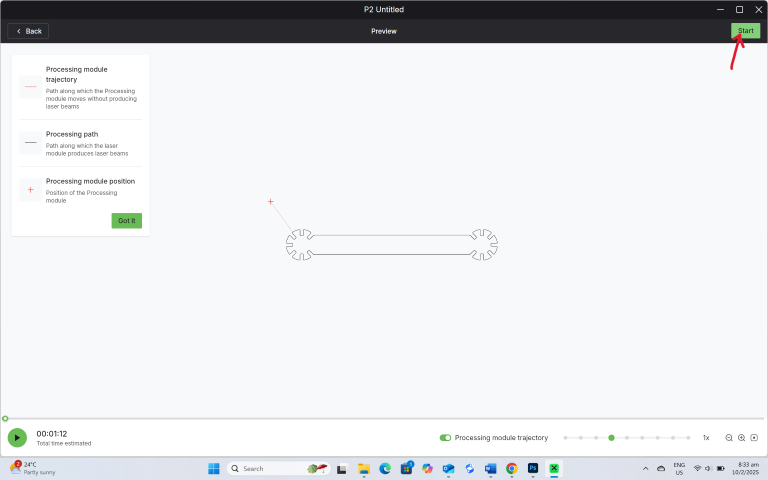
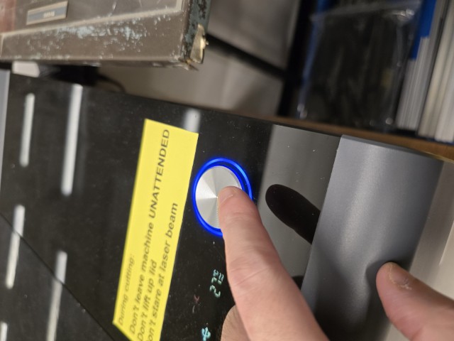
8. Press the start button on the P2 to start the job
When at first you don’t succeed…
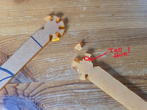
Documenting your mistakes is part of Fab Academy. I cut out my first prototype and upon testing the fit, I experienced an unexpected problem. The teeth broke off easily when pressed together. I had made the prototype too small and hence the teeth were too small and weak to resist the stress of fitting. Back to the (Fusion 360) drawing board!
Trying again
The fit test could not be done for the first prototype but here are some valuable things I learnt:
• Do not make the pieces too small. By making the pieces larger (while having the connection gap remain constant), I can give the pieces more strength to resist breakage.
• The dumbbell shaped design can be further broken down into two circular hubs and a bar. Perhaps expressing the dumbbell as separate pieces will give me more construction options.
Test fitting
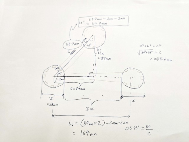
With these insights, I went back to Fusion 360 to adjust the design. Following the steps outlined in the previous section, I created the drawings for two new parts to test fit. An important concept in laser cutting is kerf. In simple terms, when you cut something from a digital drawing, the virtual dimension does not match the exact physical dimension because the laser burns away a tiny bit of the edge when cutting the material. For example, if I set the virtual dimension of a square as 3mm X 3mm, and when I measure the physical dimension, it ends up being 2.8mm X 2.8mm, the kerf is 0.1mm. This means that you must compensate for kerf when adjusting your virtual dimensions. This is also why test fitting is necessary to get a good fit when laser cutting. I started with just cutting out a single circular piece and testing it against the material thickness to assess the fit. I found that by setting the gap width to 2.5mm, I can get the pieces to fit without falling apart. But the fit still feels too tight.
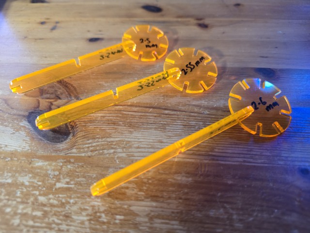
Working in 0.5mm increments, I found a good fit at 2.6mm. It should be tight enough, so the parts do not fall out when shaken, but not too tight that it is difficult to separate. This is where parametric design shines – I just need to go back to Fusion 360, change one dimension (e.g. from 2.5mm to 2.55mm), and the entire design updates.
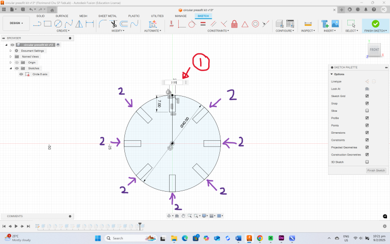
When you change 1, all the 2’s will change too. This saves a lot of time as you do not have to change each and every dimension individually. You can also change the parameters by going to the Parameters table (Modify > Change Parameters). Once the fit has been established. I proceed to cut out more pieces of the construction kit as shown in the image below.
Video of the construction kit pieces being cut out by the xTool P2
The “Bendy”
Did they say you get extra credit for including elements that aren't flat? While extra credits in Fab Academy are like points in “Whose Line is it Anyway?” (It feels good to get them but doesn’t really matter anyway), I decided to explore curved elements as I felt excited to add a third interesting piece to my construction kit. I call this piece “Bendy”. Unlike the previous parts, I did not start drawing them in Fusion 360 but went straight to CorelDraw to draw the part.
Once done, I proceed to cut out one piece to test.
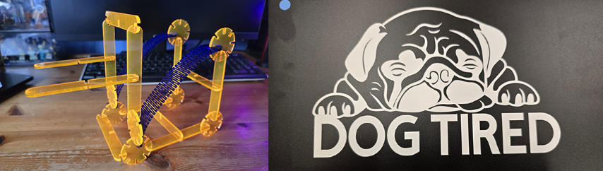
Success! It bends without breaking so I can now cut out more pieces of “Bendy” and try to create some things with my construction kit.
Construction Kit
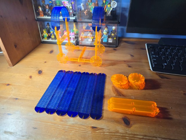
With just 3 different types of components, I was pleasantly surprised I could make quite a few different things. Here are some of my favourites:
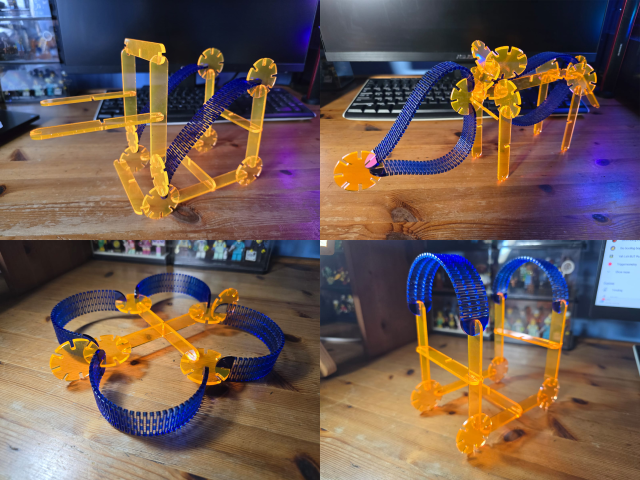
Clockwise from Top Left: Forklift, Animal, Drone and Wagon
After completing this assignment, I am quite happy with the result. However, I felt the construction kit can benefit by adding just a few more pieces such as an L-joint and T-joint. If I had more time, perhaps I will revisit this in the future.
Individual assignment - Vinyl Cutting
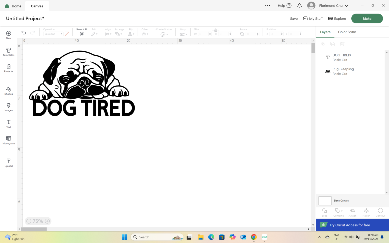
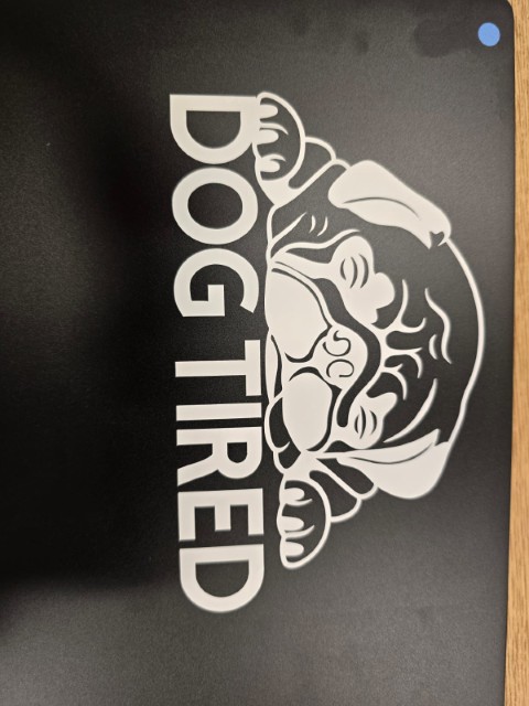
For this assignment, I used the Cricut Joy Xtra digital cutting machine to create a laptop sticker. I start by creating a simple design in Cricut Design Space. Cricut Design Space has many pre-made design templates, so I just downloaded a design and added some text to it. (Note: I had free access to the pre-made design templates through a workshop conducted by Cricut, otherwise I would need to pay to use them.
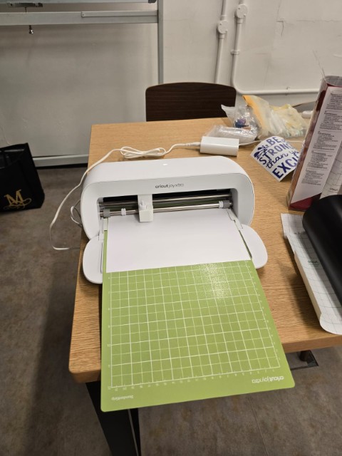
Once the design is done, I sent it to the Cricut Joy Xtra for cutting. Here are the steps:
1. Set up the machine: Plug in the power cable, open the machine, and connect it to your device via Bluetooth
2. Select your machine: Choose your Cricut Joy Xtra machine from the list
3. Select your material: Choose the material you want to use and select the correct setting
4. Load the mat: Place the material on the mat, align it, and insert the mat between the guides
5. Press Go: The machine will start cutting
6. Unload the mat: When the cut is complete, select Unload in Design Space
Once the cutting is finished, I use the weeding tool to remove all the parts of the vinyl that are not part of the design. This must be done carefully to ensure that all the parts of the design are intact.
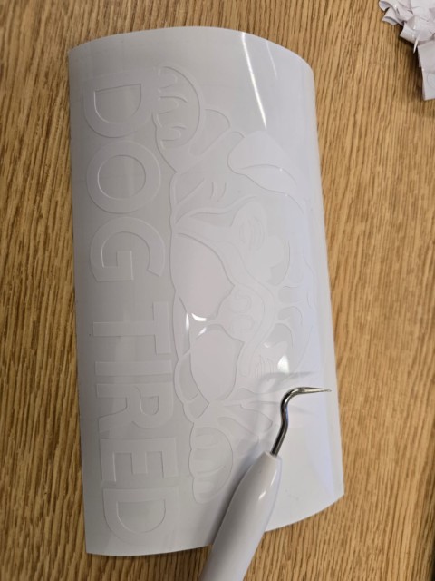
I put the (weeded) design onto the transfer tape and then position it carefully on my laptop.
Next, I use a plastic pressing tool to press on the transfer tape, ensuring that my vinyl cut design carries over and sticks onto the surface of my laptop. It is a tricky task to do and must be done with care and patience because you can take away parts of the design with it if you remove the transfer tape too hastily. If the transfer tape is taking away some part of the design with it, simply put the transfer tape back and use the tool to press again until the design sticks properly. Once that is completed, the vinyl cut is done. =)
With the conclusion of this vinyl cut, I conclude my documentation for this week. Onward to the next!
Design Files
Fusion 360 Parametric Design (.f3d)