Week 03 - Computer Controlled Cutting
Group Assignment:
1. Do your lab's safety training
2. Characterize your laser cutter’s focus, power, speed, rate, kerf, joint clearance and types
Safety Training
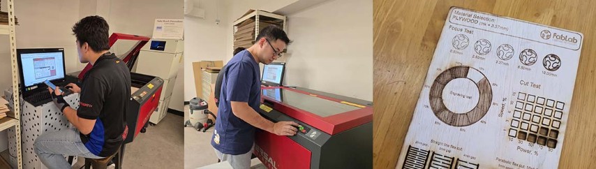
As Staff of Fab Lab Singapore Polytechnic, we have both previously completed our lab’s safety training and can move right into the laser cutter characterization.
Here are some safety rules that we would like to share:
• Never Leave the Laser Unattended – Always monitor the machine while it's running to prevent fires.
• Use Only Laser-Safe Materials – Avoid materials that release toxic fumes (e.g., PVC, vinyl) or are highly flammable.
• Ensure Proper Ventilation – Use an exhaust system to remove smoke and harmful fumes.
• Don't stare at the laser – When cutting, do not stare at the laser.
• Keep a Fire Extinguisher Nearby – Preferably a CO₂ or dry powder extinguisher for quick response.
CHARACTERIZING OUR LASER CUTTER
Laser Cutter Specs
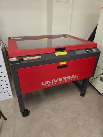
Manufacturer: Universal Laser Systems Model: VLS6.75
Laser Material Processing Area (W x H): 813 x 457 mm
Maximum Part Size (W x H x D): 940 x 584 x 203 mm
Overall Dimension (W x H x D): 1118 x 991 x 914 mm
Available Focus Lenses: 50 mm HPDFO™ (High Power Density Focusing Optics)
Laser Platform Interface Panel
Five button keypad
Computer Requirements Requires dedicated PC with Windows® 7/8/10/11 32/64 bit and one available USB port (2.0 or higher)
Optics Protection Integrated with included gas assist
Cabinet Style Free-Standing
Laser Options 10, 30, 40, 50, 60 and 75 Watts (Ours is a 60 Watt)
Weight 325 lbs (147 kg)
Power Requirements 110V/10A, 220V-240V/5A
Exhaust Requirements Two 4 in (102 mm) ports
Source: Manufacturer’s website
Definitions
In this section we referred to the definitions provided by a previous Fab Academy team from Charlotte Latin Fab Lab that had completed the same assignment last year.
• Focus: the focus is the diameter of the emanating laser beam, which is around 6.35 mm. Focal length is the distance between the lens and the material below. Focus lens refers to the series of mirrors that the laser beam is directed through; it ensures high-quality engraving and precise cutting
• Power: the power is the intensity of energy delivered by a laser beam per second. 100% represents the highest amount of power possible. • Speed: the speed is how fast the laser head is moving in the x and y directions; whereas faster speeds lead to short exposure times, slow speeds lead to long exposure times (exposure time = duration a material is exposed to a certain condition)
• Rate: laser cutting rate is the rate at which the laser cuts the material, expressed in length per unit time. It changes with material type, material thickness, width of cut, etc.
• Kerf: Kerf is the width of the material removed by the laser beam; it is affected by the intensity of the laser beam, the type/thickness of the material, and the focal length.
• Joint clearance and types: Joint clearance refers to the intentional gap between different components; similar to the kerf, this enables proper fit during assembly.
Template for testing
For our tests, we started with this template from 3axis and then modified it for our testing needs.

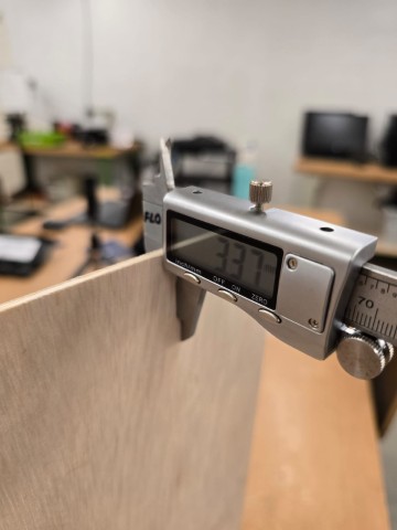
For our tests, we used a plywood board that we measured to be 3.37mm thick.
Focus Test For the focus test, we adjusted the Z-axis value to 0.5mm, 2.5mm, 3.37mm, 6.5mm and 10mm and then started the laser cutter to engrave at a constant power and speed to see if the focus of the laser itself had any effect.
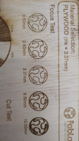
The results show that there was no discernible difference between the first three values, but the outline darkened and became thicker for the last two values. We learnt that this is because there is a range of values of which the laser still focuses sharply and only by going beyond those values, which discernible differences in outline be seen.
Engrave Test
For our engrave test, we increased the power setting gradually in 10% increments, while keeping the speed constant.
While we expected the engraving to gradually become darker, the actual result seemed to happen in bands:
10% - No effect
20% - 50% - Darker shade, no browning of the edges
60% - 100% - Darker shade with browning at the borders
More material was removed at each increasing power setting, creating a stepped effect.
Cut Test
The intention of the cut test is to assess how the laser cutter performs under different speed and power combinations. We failed our first attempt because we used too high of a power setting and the entire row of squares were burnt.
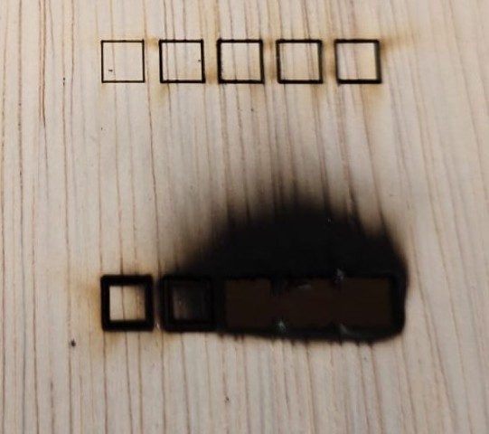
Knowing this, we attempted the cut test again, this time with a lower upper limit value for the power setting (only up to 50%).
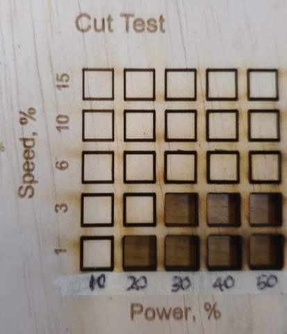
This time, we can see a pattern with the results.
Speed from 6% to 15% - None of the squares managed to cut through.
Speed at 3% - Only power values from 30% to 50% can cut through the material. Lower power values at this speed failed to cut through the material.
Speed at 1% - Like the result above, except now that at power value of 20%, the material manages to cut through.
From the cut test, we learnt that by adjusting the speed/power combination, we can affect the cutting effect of the laser cutter. For example, if the material is not cutting through at Speed = 3% and Power = 20%, you can either increase the power to 30%, or decrease the speed to 1% to cut through the material.
Flexi cut
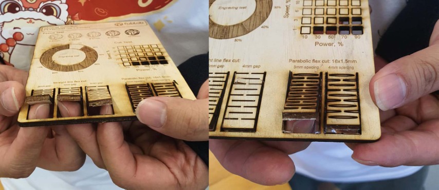
The intention of the Flexi cut is to be able to achieve bending cuts on the material. There are a variety of cuts that can be used to achieve the bending result (such as straight line and parabolic flex cuts). In this test, we succeeded in achieving the bending result with all five of the flexi cut joints.
Kerf Test
An important concept in laser cutting is kerf. In simple terms, when you cut something from a digital drawing, the virtual dimension does not match the exact physical dimension because the laser burns away a tiny bit of the edge when cutting the material.
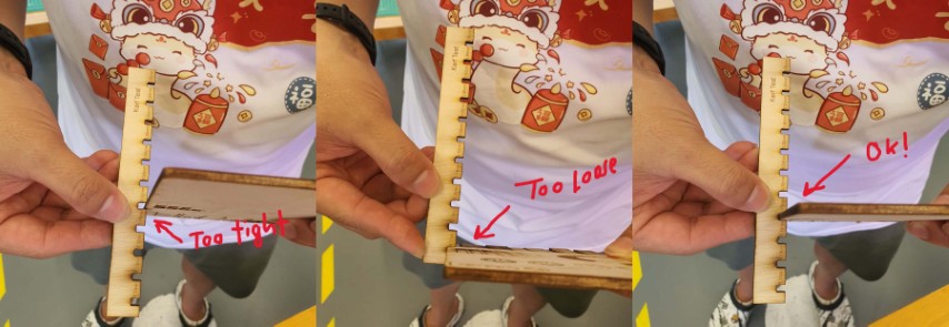
By performing the fitting test, we found that the values of:
3.10mm and below – Too tight. Cannot go in.
3.30mm – Too Loose.
3.15mm – Just right. Achieves a snug fit.
What this tells us is that to achieve a snug fit joint with a measured thickness of 3.37mm, you will need to input a virtual dimension value of 3.15mm (tighter) because the laser will burn of some additional material from the cutting path in the process of cutting.
With this, we conclude our documentation for this week’s Group Assignment.
Test files
Focus, Engrave, Cut and Flexi Cut tests (SVG)