Week 09 - Input Devices

Group assignment:
• Probe an input device(s)'s analog levels and digital signals
• Document your work on the group work page and reflect on your individual page what you learned
Individual assignment:
• Measure something: add a sensor to a microcontroller board that you have designed and read it.
Group assignment
For this week’s Group assignment, I teamed up with my fellow Fab Academy buddy Haw Ren to use the test equipment in our lab to explore a potentiometer and an ultrasonic sensor.
The documentation for our Group assignment can be found here.
Group assignment reflection
From my experience measuring both analog and digital signals for a potentiometer and the ultrasonic sensor, I learnt in detail how they are used to control voltage and measure distance respectively. There is some math to work out in both instances, and I had made some mistakes in interpreting the formulas. But once that was sorted out, I gained a better understanding of how electronic input devices work.
Individual assignment
Overview
For this week’s individual assignment, I am exploring how to make my own capacitive touch sensor so that I can use it for my Final Project.
What is a capacitive touch sensor?
To understand what a capacitive touch sensor is and how it works, I watch this Youtube video by Mario's Ideas.
Capacitance is the ability to store charge between two conductive elements separated by an insulator (dielectric). In a capacitive touch sensor, the sensor pad acts as one plate of a capacitor. The other plate is the human finger, which is naturally conductive and connected to a large ground reference (your body and the earth).
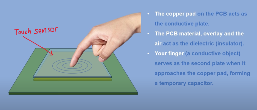
No Touch: The system has a baseline capacitance measured between the sensor pad and ground.
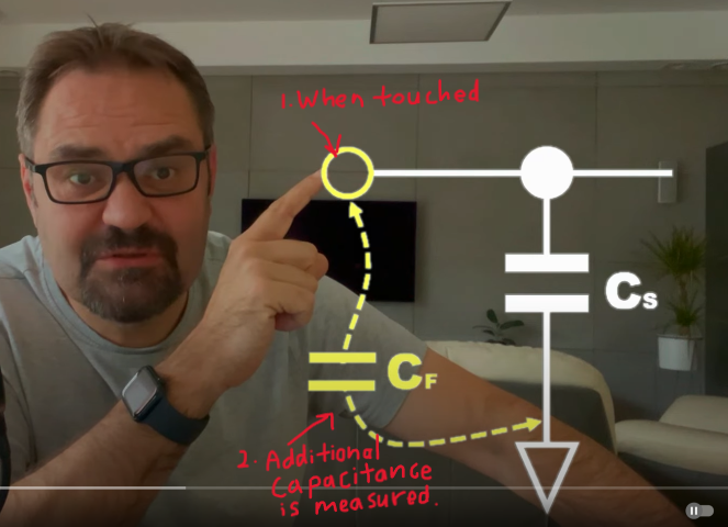
When You Touch: Your finger comes near or touches the sensor pad, increasing the capacitance because your body adds to the overall conductive surface. The change in capacitance is detected by the microcontroller or touch IC. Detection Logic: The sensor compares the new capacitance to the baseline value. If the difference exceeds a threshold, the system registers a touch event.
Creating the Touch Sensor module
To create the Touch Sensor, I used many of the processes that I learnt from the Electronics Production week. This is because in essence, the touch sensor module is just a specialized extension of the XIAO RP2040 board that I made the week before. For details of the processes, please refer to the documentation for that week.
In summary, this was what I did:
Creating the NC files
Since this was just an additional module, I did not go into Eagle to start up an entire new project. Instead, I referenced the previous PNG files for my XIAO RP2040 board and went straight into Photoshop to draw up my design for the touch sensor module. It has a simple design with 3 buttons.
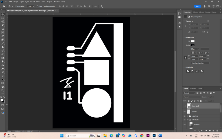
As shown in the image below, once the trace and the outline PNGs have been created, I go into Mods to generate the NC files that are needed for milling the touch sensor module.

Milling the Touch sensor module
For this part, I use a Stepcraft 420 desktop CNC milling machine to mill the touch sensor module.
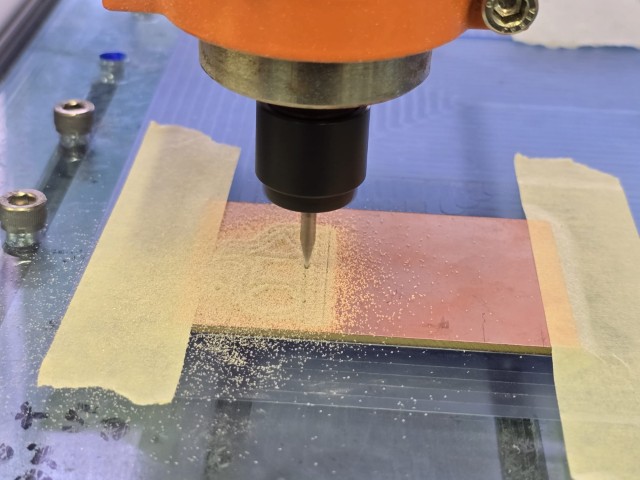
I secure the board to the milling bed, then use a V-bit engraver to mill the traces. After the traces have been done, I move on to change out the V-bit engraver to an endmill and then cut out the touch sensor module using the NC file for the outline.
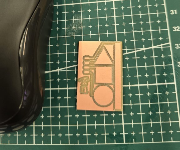
The touch sensor module board looks like this after I clean off all the milled dust.
Soldering the header pins
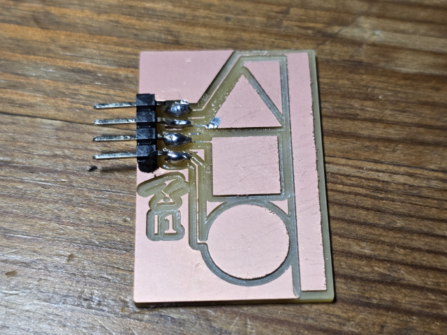
Next up, I solder the header pins to the touch sensor module so that I am able to connect it to my XIAO RP2040 board.
Testing the touch sensor
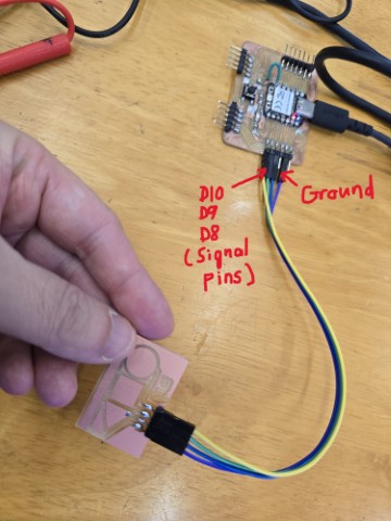
To test the touch sensor, I connect it to my XIAO RP2040 board as shown below.
Program
I need a program to test the touch sensor, so I used this Arduino program. It only runs one button, but it is sufficient to test if the sensor works.
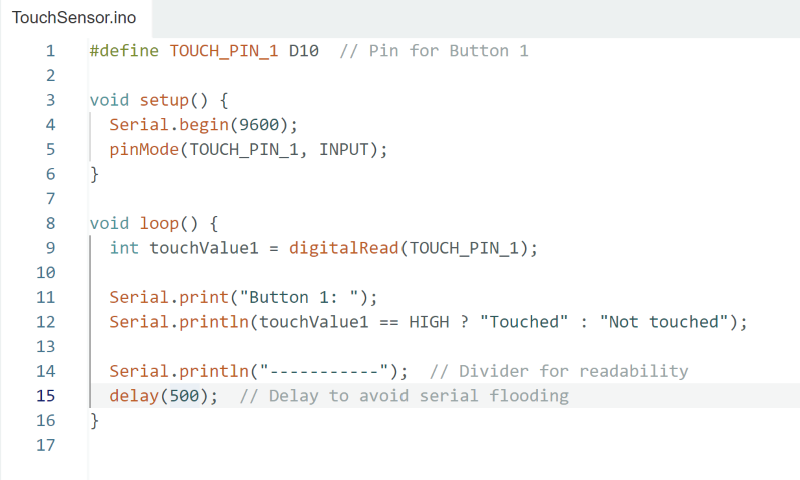
The program will display “Touched” when it receives a touch sensor and “Not touched” when there is no signal. The text is not very clear in the (low-resolution) video but you can see in the video below that the serial monitor switches between a short length of text “Touched” and a longer length of text “Not touched” that coincides with touching and not touching the sensor. It lags a little, but I think it mostly works.
IT DOESN’T WORK AND HOW I ADDRESSED IT
I found out the next day that I had gotten the entire concept of capacitive touch sensors wrong and had used the wrong program.
Here are the things I got wrong:
1. Different shaped buttons – I had previously thought that it did not really matter if you made 3 different types of buttons (Triangle, square and circle) running on the same code. This is wrong because Capacitance is affected by the surface area of the button, so if you want to make 3 different buttons, they need to be of the same area for all of them to trigger at the same threshold.
2. Wrong program – Sometimes a program can look plausible, but it doesn’t really work. What my program did was to sense a touch ONCE, set it to a HIGH state and then left it there until it reset. It does not consider how a capacitive touch sensor works, which is to sense the change in capacitance to let it know whether it is on or off. Here is a YouTube video from Sparkfun Electronics that I watched that explains how it works in detail.
Here is how I addressed the issues:
1. Addressed issue: Different shaped buttons – I redid my touch sensor module, this time with 3 buttons of the same size.
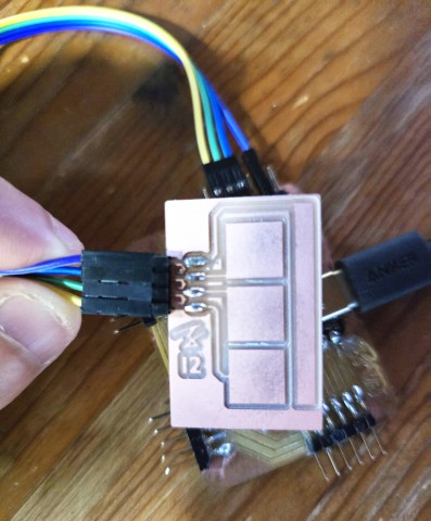
2. Addressed issue: Wrong program – To address this issue, I sought help from my instructor, Steven. This is the code he provided.
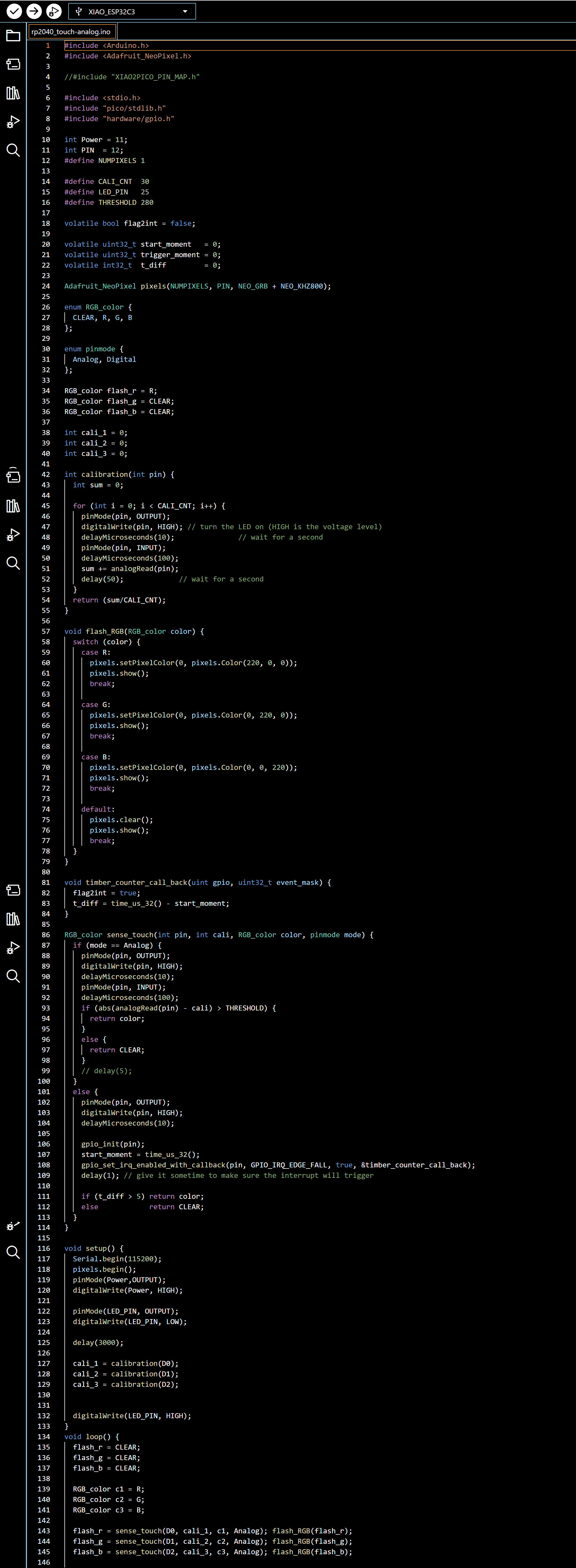
A step-by-step explanation from Chat GPT can be found here in a separate document, but in short…
This Arduino code is written for a XIAO RP2040 to detect capacitive touch on three input pins (D0, D1, D2) and provide visual feedback via a RGB LED. The code begins by including libraries for NeoPixel control and low-level hardware access. It sets up some constants, calibration variables, and a NeoPixel object with one LED.
The calibration() function measures a baseline analog value for each touch pin to compare against later.
The flash_RGB() function lights the NeoPixel in red, green, or blue based on touch input.
The sense_touch() function either uses analog or digital sensing (based on pinmode) to detect a touch event by comparing the measured value to the calibrated baseline (cali). If a significant change is detected, it returns the associated color.
In setup(), the pins are initialized, and each input pin is calibrated. The loop() repeatedly checks for touches on the three pins and lights the NeoPixel with red, green, or blue accordingly. This allows a basic capacitive touch interface with color-coded feedback using a single NeoPixel. This program will show different RGB light on my PCB - RED (220, 0, 0), GREEN (0, 220, 0) and BLUE (0, 0, 220) when I touch each of the different button pads.
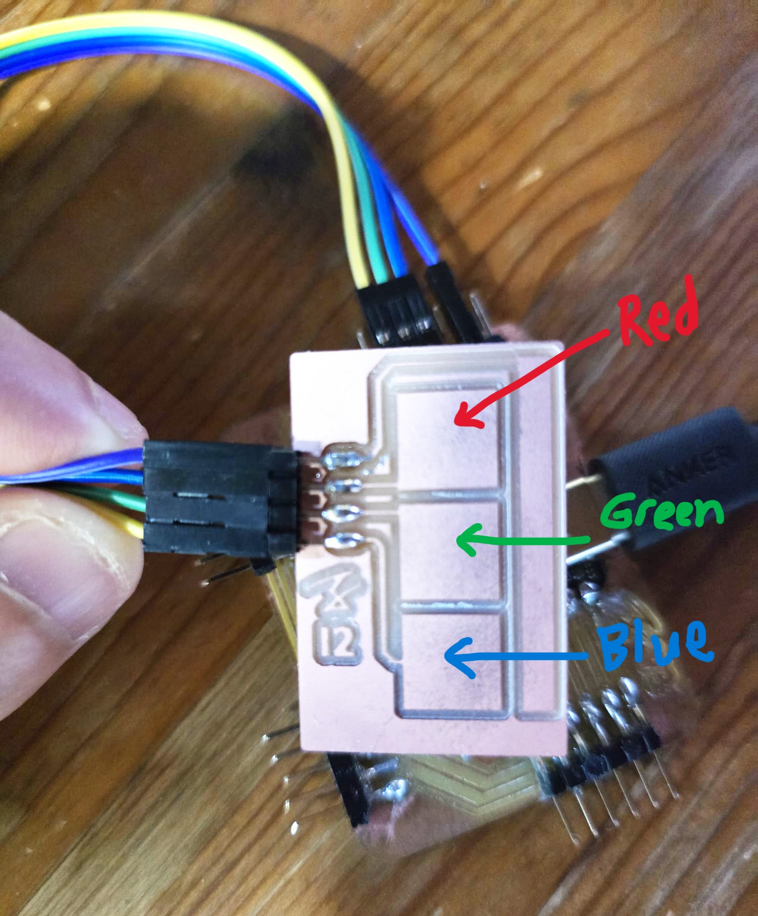
The key to getting this code to work is to adjust the threshold value and I found that for my touch sensor module, the value was 280. Below is a video of the touch sensor working.
Reflection
This week was another tough electronics week and while I tried to pick up as much as I could, I still fell short and needed more time to address the things that I got wrong. I continue to struggle a lot with the electronics theory and programming aspects of this week’s learning objectives, and I still do not feel very confident about doing it on my own.
Still, I learnt a lot (through failing) this week and I am looking forward to using what I learnt this week for my final project.
Files
Touch Sensor Program CORRECTED
This concludes this week’s assignment.
