Week 09 - Input Devices

Group Assignment:
• Probe an input device(s)'s analog levels and digital signals
• Document your work on the group work page and reflect on your individual page what you learned
Overview
For this week’s Group Assignment, we explore the following input devices:
• Potentiometer
• Ultrasonic Sensor
Potentiometer
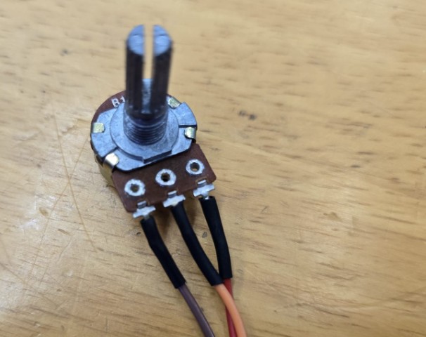
For an explanation as to what a potentiometer is, we turned to ChatGPT with the following prompt:
What is a potentiometer? Explain to me in simple terms please.
ChatGPT reply:
A potentiometer, or "pot" for short, is a type of variable resistor. Imagine it like a volume knob on a radio — as you turn it, the volume changes smoothly from low to high. Inside a potentiometer, there is a strip of resistive material, and a movable contact called a "wiper." When you turn the knob, the wiper moves along the strip, changing the resistance and adjusting the electrical flow.
In simple terms:
• Turning the knob one way makes it easier for electricity to pass (low resistance).
• Turning it the other way makes it harder (high resistance).
Potentiometers are often used to control things like volume, brightness, and speed in electronic devices.
Setup
We set up the potentiometer to control the brightness of an LED. We then measure the analog signal with a multimeter to see how it behaves.
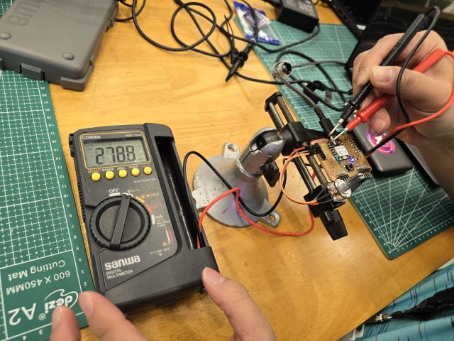
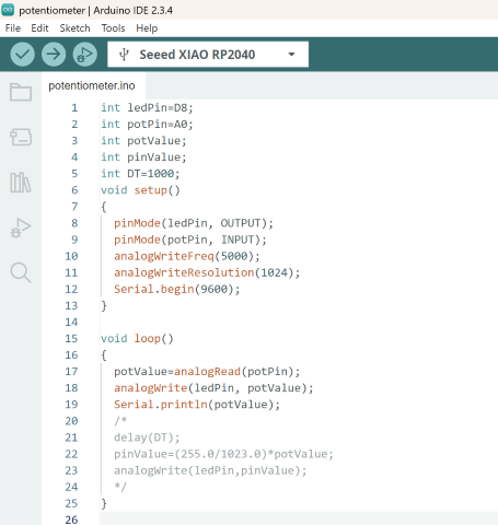
Using a multimeter, we probe the XIAO RP2040 board with one probe at the AO analog pin, and the other probe at ground to measure the voltage across the potentiometer. We also need a code to control the potentiometer. For this, we use code (with edits from our instructor, Steven) from this website (www.geeksforgeeks.org).
Signal Measurement
RP2040 ADC has 12-bit resolution. For this example, we configured the ADC for 10-bit resolution (1024 steps).
For an anolog input voltage of xxV, the digital code was nnn. This gives a calculated voltage of xxV, which compares well with the measured voltage.
Analog Voltage (xxV) = (Ref Voltage/1024) X Digital code (nnn)
For Lowest value:
Measured Voltage = 0.9mV
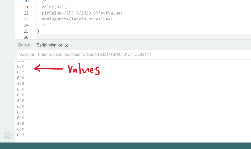
The corresponding Serial print value here is 2. The Serial print value can be read in Serial Monitor as shown below.
Analog Voltage = (3.3V/1024) X 2 = 0.64mV
For Middle value:
Measured Voltage = 1.954V
The corresponding Serial print value here is 607.
Analog Voltage = (3.3V/1024) X 607 = 1.956V
For Highest value:
Measured Voltage = 3.29V
The corresponding Serial print value here is 1018.
Analog Voltage = (3.3V/1024) X 1018 = 3.27V
The measured voltage values are very close to those of the calculated voltage values. Comparing the two sets of values, we can conclude that our readings are accurate. From what we understand, the voltage VS analog read values follow an almost linear line. We also observed that the LED brightness increases as we adjusted the potentiometer to a higher voltage. Below is a video capturing the measurement process.
Ultrasonic Sensor
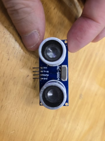
For an explanation as to what an ultrasonic sensor is, we turned to ChatGPT (again) with the following prompt:
In simple terms, explain to me what an ultrasonic sensor is.
ChatGPT reply:
An ultrasonic sensor is like a bat's echolocation system — it uses sound waves to measure distance!
Here's how it works in simple terms:
• The sensor sends out a high-pitched sound wave that we can't hear (like a quick "beep!").
• That sound wave hits an object and bounces back to the sensor, like an echo.
• The sensor measures how long it takes for the echo to return.
• Using the speed of sound, it calculates how far away the object is.
So, an ultrasonic sensor can tell how close or far something is without touching it. It is used in parking sensors, obstacle-avoiding robots, and automatic doors!
Now knowing what an ultrasonic sensor does, we set it up for some measurements.
Setup
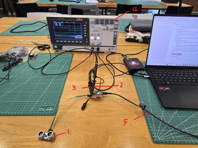
To measure the signals from the ultrasonic sensor, we set it up as follows:
1. Ultrasonic Sensor
2. Probe to measure trigger (input) signal CH1
3. Probe to measure echo (output) signal CH2
4. Oscilloscope
5. USB power (to the XIAO RP2040)
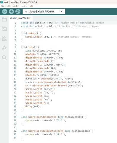
We needed a program to control the ultrasonic sensor and so we used the code from this website (www.tutorialspoint.com):
Signal Measurement
In this video, we measure the distance from the ultrasonic sensor to our hand. We then analyze the signal on the oscilloscope.
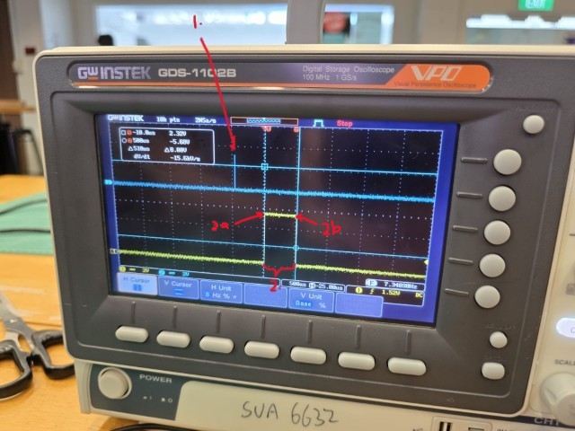
From the oscilloscope, we observe the following:
1. There is a trigger signal on CH1. This is the signal that tells the ultrasonic sensor to emit a sound.
2. The return of the sound is captured on CH2. If the distance is farther away, then the wave measured between 2a and 2b will be longer.
We can calculate the distance of the object from the ultrasonic sensor to the target object using this formula:
Distance = Speed x Time
In the screen capture of our signal (above), the wave measured between 2a and 2b is 1.40ms.
With the speed of sound in air being 344 m/s, we get:
Distance = 344m/s x 0.915ms = 344m/s x 0.000915s = 0.31476m = 31.5cm
However, this Distance refers to the time the sound travels from the ultrasonic sensor to the target, and then BACK AGAIN. Thus, to get the actual distance, we need to divide the earlier result by 2:
Distance (Actual) = 15.75cm
Conclusion
From our experience measuring both analog and digital signals for a potentiometer and the ultrasonic sensor, we learnt in detail how they are used to control voltage and measure distance respectively. There is some math to work out in both instances, but once we figured out what the formulas were doing, the measurements made a lot more sense.
