Week 07 - Computer-Controlled Machining

Group assignment:
• Complete your lab's safety training
• Test runout, alignment, fixturing, speeds, feeds, materials and toolpaths for your machine
• Document your work to the group work page and reflect on your individual page what you learned
Individual assignment:
• Make (design+mill+assemble) something big
Group assignment
For this week’s Group assignment, I teamed up with my fellow Fab Academy buddy Haw Ren to test and use the Versatil 2500, a large format CNC machine.
The documentation for our Group assignment can be found here.
Group assignment reflection
At first glance, the CNC machine looks like a big, intimidating machine. However, after learning to use it, it turns out that the CNC machine is actually quite easy to understand. I think of the CNC machine as a drill connected to a motor. Here are some of the things that stood out the most about the CNC machine:
1. Make Big - It can cut out large stuff (meter scale)
2. Dog bone - It cannot cut sharp inside corner holes due to the round shape of the end mill. If the inside hole needs to fit a male joint of the same size that has sharp right-angled corners, a bit more material needs to be removed at the corners to form a “dog bone” shape.
3. Blind - You have to keep reminding yourself that the CNC machine cannot “see” where it is cutting. If it is not calibrated properly, the tool head of the CNC machine may move to a space where it might be obstructed and break.
4. Safety first - Proper safety must be observed when using the machine. Wear PPE (safety eyewear, earmuffs) and stay away from the moving parts when the machine is running. Work in pairs/groups if possible.
5. Measure twice, cut once - When making joints for CNC-milled parts, it is important to understand the material thickness and the clearances and offsets required to achieve those joints. Too tight, and a lot of post processing is needed to sand it down to fit. Too loose, and the joints will not even work. Oh, and the old adage of “measure twice, cut once” is very appropriate in CNC machining. You can also test cut a small section to test fit before committing to the main cut.
Individual assignment - Makerspace Sheet Material Shelf
DESIGN
Why do this?
I decided to embark on this project because our current rack for our Makerspace’s laser cutting materials was not very user-friendly and I finally decided to try to fix it.
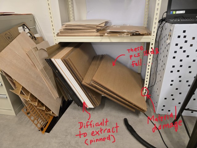
As you can see from the photo above, this particular rack stores 10mm acrylic sheets. 10mm acrylic sheets are very heavy and are not easy to handle (I can only lift 2 sheets comfortably at a time, with 4 sheets being the max). These materials have very sharp edges and can cut and cause injuries if not handled carefully. Moreover, these material sheets also tend to slide and if they slide too much, they can fall in awkward orientations that makes extracting them very difficult. When the material slides or falls, it can also chip and damage the material. As such, I thought of improving the shelf by adding shelf partitions to keep the material sheets mostly upright and prevent the materials from sliding or falling into awkward positions.
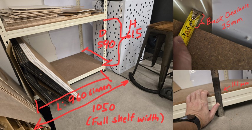
Dimension Measurement
As I am working to fit an existing rack, I take measurements of all the dimensions that I need to work with. I need to be careful here or else the rack might not fit if I make mistakes with the measurements.
Real-world Reference
I referred to the following reference for how my sheet material shelf might look. Drawing on real-world references is a great way to kick off a design.
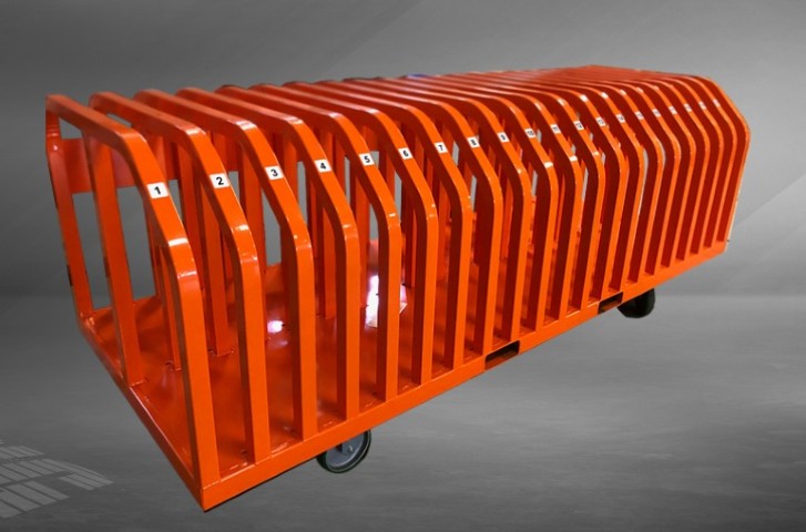
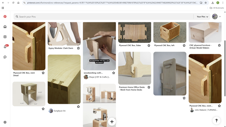
The reference that I have is from the supplier Big Steel Rack and as the name suggests, it is constructed from welded steel. As I will be machining mine out of a plywood board, I looked up some wooden joints on Pinterest to give me an idea on how I should construct my shelf. You can view my board here.
CAD in Fusion 360
When I first started exploring Fusion 360 in Week 02, a good tip I learnt was to sketch out the idea on paper before going to Fusion 360 to model it. Here is the sketch I drew that helped me visualize my idea.
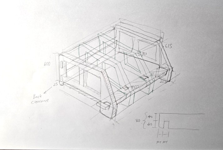
The process of modelling was straightforward. I only had two different parts that I needed to create. I start by creating some custom parameters.

Then I create sketches based on those custom parameters.
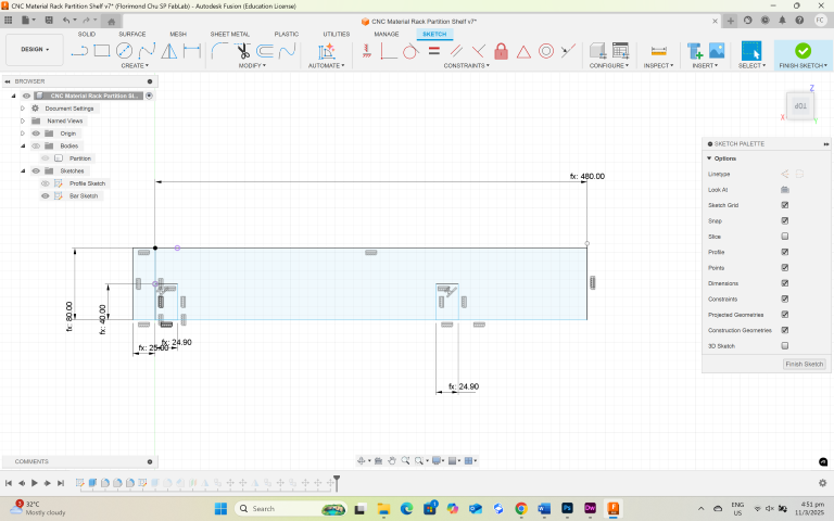
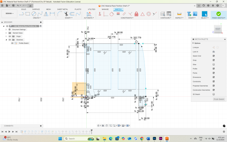
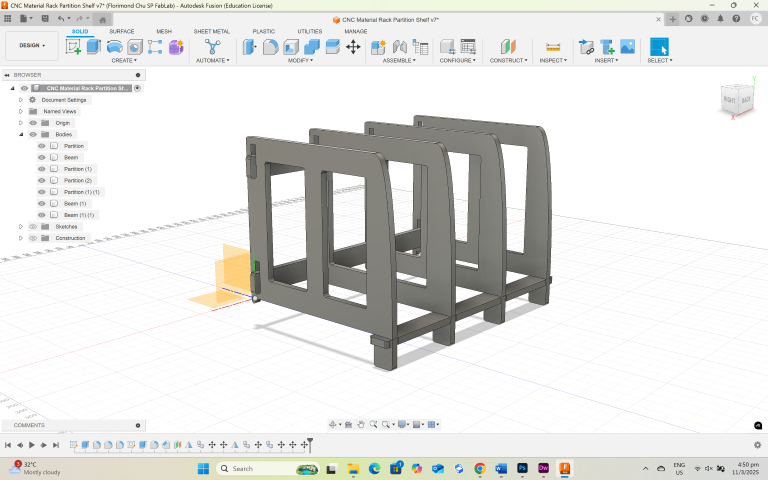
From the sketches, I use functions such as extrude and mirror to create the geometry that I need for the shelf. I now have the two different parts I need.
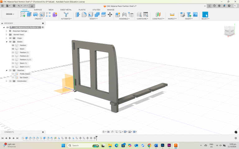
Next, from those two parts, I duplicate and move them into place to form the final assembled rack.
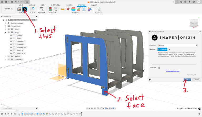
With the CAD model completed, I use the Shaper Utilities plug-in to export the outlines as SVGs, which I will need to use to define the toolpath for the CNC cutting process later on.
CNC Cutting
VCarve Pro to create the toolpath
To explain the process of creating the toolpath using VCarve Pro, I use the following ChatGPT prompt:
Can you provide a step-by-step guide for beginners to get started with CNC with VCarve pro?
Using the Chat GPT reply as the structure, I compared it with my own experience (in italics). This approach helps me to recap the workflow, with the added benefit of covering some things that I did not do (or know) but might be useful for future reference. The explanation is as follows:
Step 1: Understanding CNC and VCarve Pro
• CNC (Computer Numerical Control) machines use pre-programmed software to control tools like routers, mills, or lasers.
• VCarve Pro is a popular CAM (Computer-Aided Manufacturing) software that helps design and generate toolpaths for CNC machines.
Step 2: Installing and Setting Up VCarve Pro
1. Download & Install
o Download VCarve Pro from Vectric’s official website.
o Install it following the on-screen instructions.
o You can use the free trial version to explore features before purchasing.
My Experience: I skipped this section since VCarve was already installed on the PC that controls the CNC machine.
2. Open VCarve Pro
o Launch the software and start a New Project.
My Experience: I launched the software but rather than start a new project, I opened the SVG that I created from Fusion 360.
Step 3: Creating a New Project
1. Set Up Job Dimensions
o Define material size (width, height, thickness).
o Choose Z-zero position:
• Top of the material (common for wood projects).
• Machine bed (better for precise cuts).
o Select the XY datum position (typically lower-left corner).
My Experience: VCarve has a Job Setup section that allows you to input the settings mentioned above. Below is a screen capture of my settings.
2. Import or Create a Design
o Use vector drawing tools in VCarve to design your part.
o Import existing designs (SVG, DXF, AI, etc.).
o Add text, shapes, and objects as needed.
My Experience: I imported an SVG file for this step (Open an existing file) .
No additional design elements were added. However, I did use the fillet tool to create "dog bones" for my inside corners.
Step 4: Setting Up Toolpaths
1. Select Your Tool
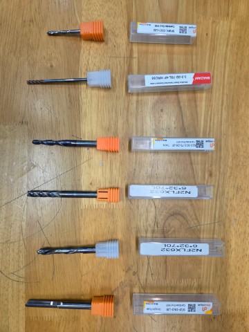
o Open the Tool Database and choose an appropriate bit:
• End mills for cutting out shapes.
• V-bits for engraving.
• Ball nose bits for 3D carving.
My Experience: I used an end mill since I am only cutting out shapes.
2. Choose the Toolpath Type
o Profile Toolpath (cut along a line or outside a shape).
o Pocket Toolpath (remove material inside a shape).
o V-Carve Toolpath (engrave with V-bit).
o Drilling Toolpath (create holes).
o 3D Toolpath (for detailed carvings).
My Experience: I used Profile Toolpath as I am doing a through cut.
3. Adjust Cutting Depths & Feeds/Speeds
o Cut Depth: Ensure it does not exceed your material thickness.
o Feeds & Speeds: Choose settings appropriate for your material and bit.
4. Preview the Toolpath
o Click Preview Toolpath to see how it will carve the material.
My Experience: 2,3 and 4 are all related to the toolpath settings so I will cover them together. I used a Profile Toolpath since I am only doing 2D through cuts.
Explanation for Toolpath settings: Under Toolpath Operations (image above), you can find the following settings:
• Cutting Depth – This is the depth that I set for how deep I want the tool to cut through. I have set this to 25.4mm for a material of thickness 25mm.
• Tool – You can access and adjust more tool settings by clicking EDIT:
a) Tool Type - We use a 4 flute 6mm diameter End Mill
b) Pass Depth = 6 mm (same as the tool diameter).
c) Stepover = 40 % (not more than 50%) This is to ensure that the end mill overlaps the previous pass so that there will not be unwanted material left behind left behind.
d) Spindle Speed = 12,000 revolutions per minute (RPM)
e) Chip load
Formula for Chip load
Chip load = Feed rate (mm per minute) / (RPM x number of flutes)
Chip load range: Between 0.025mm to 0.25mm.
Using the formula above, the chip load is automatically calculated by the software. With a Feed Rate of 4,500 mm/min and a spindle speed of 12,000 RPM X 4 Flutes, the chip load works out to be 0.09375mm which is within the acceptable chip load range.
f) Plunge Rate = 600 mm/min (the speed that allows the end mill to drill into the material).
g) Tool number = 1 (no tool changing option).
• Passes (accessed by clicking edit passes) refers to the number of times that the end mill will travel along the cutting path to cut down the required depth. For my job, it is 5 passes, with each pass being 5.08mm deep.
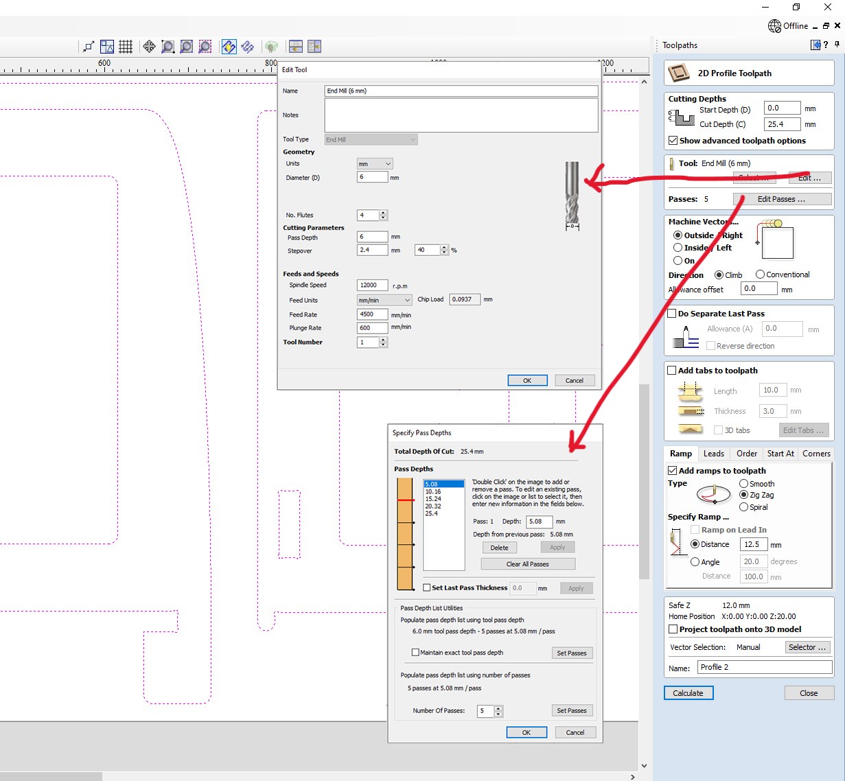
• Machine Vectors - I select Outside/Right and Climb Milling
Which One Should You Use?
Climb Milling is suitable for CNC machines with minimal backlash and when a smooth surface finish is required.
Conventional Milling is appropriate for older machines, harder materials, or rough cuts.
For woodworking, climb milling can reduce tear-out.
For metalworking, conventional milling may be safer for rough passes, while climb milling is used for finishing.
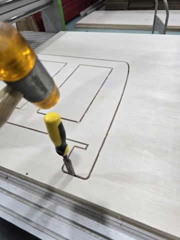
• Tabs keep the parts do not fly off during the cutting process. They can be chiselled off later. Tabs can be added manually or automatically.
• Ramps help the tool to ease into the cut at an angle rather than going straight in to reduce resistance from the material.
When done with the settings, click Calculate to generate the toolpath. A warning occurs because the set value is more than the material stock thickness.
This is okay as we have a sacrificial board below the stock, and the cutting bed will not get damaged. The advantage of using a sacrificial board is that because a material like plywood is not uniform in thickness, cutting a little past the measured material thickness helps to ensure that the entire cut cleanly cuts through.
You can also preview your toolpath, and the estimated time required for the job.
Step 5: Exporting G-Code for CNC Machine
1. Select the Correct Post Processor
o Different CNC machines require different post processors (e.g., GRBL, Mach3, Shapeoko, etc.).
o Find the correct one for your CNC and select it.
2. Save the Toolpath
o Click Save Toolpath and generate the G-code file.
My Experience: When done with the settings in the previous step, I save the toolpath ensuring the details are correct: --> Visible toolpaths to one file. --> Check the toolpaths. --> Machine = Versatil 2500. --> Post Processor = G-Code (mm) (*.tap) --> Save Toolpaths(s).
Toolpath preview image below:
Step 6: Running the CNC Machine
1. Transfer G-Code to CNC
o Load the G-code into your CNC’s control software (e.g., Universal Gcode Sender, Mach3, Carbide Motion).
My Experience: In my case, our CNC’s control software is NC EAS(Y) Pro.
2. Secure Your Material
o Clamp your material firmly on the CNC bed.
3. Zero the Machine
o Move the tool to the correct X, Y, and Z zero positions.
4. Run the Job
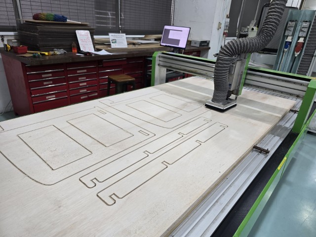
o Start the cut and monitor the machine for safety.
Step 7: Finishing the Project
• Remove excess material or tabs.
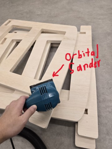
• Sand and clean the workpiece.
• Apply paint, stain, or finishing as needed.
My Experience: The Chat GPT reply did not include Parts Assembly so I will address this in the final section as Step 8.
Step 8: Parts Assembly
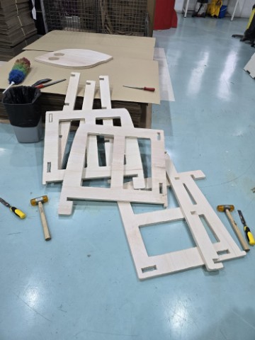
My Experience: While this part of the process should have been easy, this was not the case for me and I would like to share two learning points from my experience:
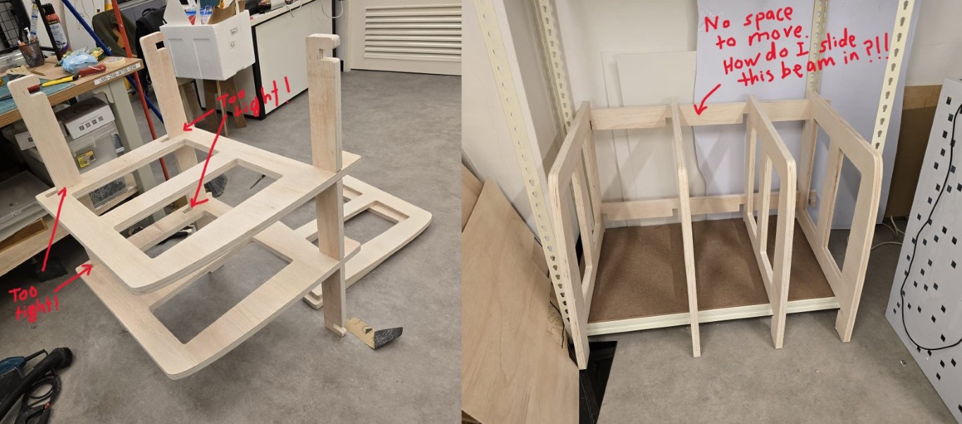
1. Test fitting – I did not leave enough offset for some of the joint fittings and some of the joints were too tight. I had to do quite a lot of sanding to ensure that the shelf could be assembled. On hindsight, it would probably be a good idea to make a small test joint before proceeding to the final cut.
2. Assembly process – We do not often think about the space and clearances required for the assembly process. We should. It was a damn struggle to be able to fit the sheet material shelf in. It felt like one of those confounding topological puzzles where you need to assemble the pieces in the exact order otherwise it will not fit. In the end, I managed to fit it in by removing the shelf that was obstructing it from above.
Final Result
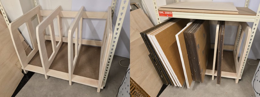
Here is the final result! I am happy to complete this assignment and also solve a real problem while doing so.
Design Files
This concludes this week’s assignment.
