Week 07 - Computer-Controlled Machining

Group Assignment:
• Complete your lab's safety training
• Test runout, alignment, fixturing, speeds, feeds, materials and toolpaths for your machine
• Document your work to the group work page and reflect on your individual page what you learned
Safety Training
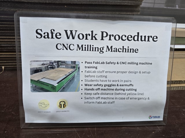
As Staff of Fab Lab Singapore Polytechnic, we completed our lab’s safety training under the supervision of our Fab Academy Instructor Steven Chew.
OUR CNC MACHINE
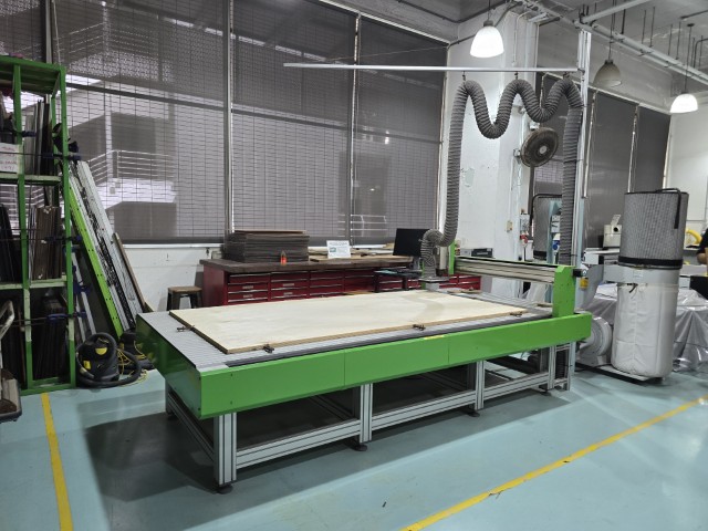
Our large format CNC machine is the EAS Versatil 2500.
CNC Specs
Model: Versatil 2500 (8 ft x 4 ft)
Machine dimensions (mm): 3200 x 1650 x 1620
Machine weight: 290 kg
Milling table dimensions (mm): 3200 x 1440 XYZ-axis travels (mm): 2500 x 1250 x 170
Z-Axis head room: 170 mm
Milling table type: Aluminium extruded T- groove plate
Travel speed: 12 m/min (200mm per sec)
Spindle motor: AC 1.1 kW (With option of 2.2kW & 3.3kW)
Max. 24,000rpm Power Supply: 230V, 50/60Hz
Drive system: 16x10mm precision ball screw driven spindles with linear slide bearing guides
Operating software: NC EAS(Y) PRO (real-time software)
Definitions
In this section we referred to (and adpated) the definitions provided by a previous Fab Academy team from Super Fab Lab Kochi that had completed the same assignment last year.
• CNC: Computer Numerical Control
• End Mill: A cutting bit used for milling
• Flute: A channel on an end mill to direct the cutting debris
• Runout: When the End Mill doesn’t spin perfectly on its centre axis and wobbles
• Spoil Board: The board on top of the machine bed that is made to protect the bed from the end mill cutting through your material
• Alignment: Levelness and straightness of the spoil board
• Fixturing: The process of securing the material to be cut on the bed
• Toolpath: The path that the endmill follows to cut the material
• Tabs: Small Sections of Material that the machine avoids cutting off to hold material in place when cutting
Safety and precautions
For this section, we used Chat GPT, and it provided a good list of safety rules.
Chat GPT prompt: What are the safety rules for large format CnC machines?
1. Personal Safety
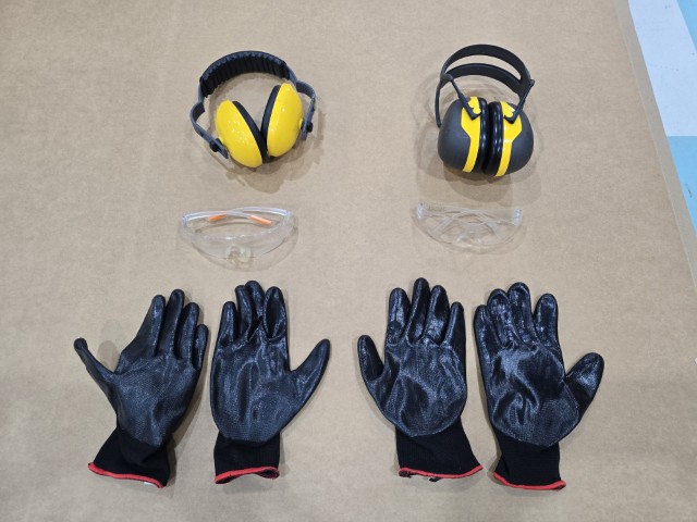
• Wear PPE: Always wear safety glasses, hearing protection, and appropriate work gloves when handling materials (but not near spinning tools).
• Avoid Loose Clothing & Jewelry: Tie back long hair and avoid baggy clothes or accessories that could get caught in moving parts.
• Use Dust Protection: Large CNC routers generate dust—use a respirator or ensure proper dust extraction is in place.
2. Machine Setup & Operation
• Inspect Before Use: Check for loose bolts, damaged cables, and worn-out tooling before starting the machine.
• Secure Materials Properly: Use clamps or vacuum tables to firmly hold the workpiece in place.
• Verify Tool Paths: Always simulate or preview the cutting path in software before running the job.
3. Safe Work Practices
• Never Reach Into the Machine While Running: Keep hands and tools away from the cutting area during operation.
• Use the Emergency Stop (E-Stop): Be familiar with the location of the E-stop and other safety switches.
• Monitor the Machine: Never leave the CNC running unattended—watch for signs of tool wear, overheating, or incorrect cutting paths.
4. Electrical & Fire Safety
• Check Wiring & Connections: Ensure cables are in good condition and properly connected.
• Avoid Flammable Materials: Some materials (like certain plastics or untreated wood dust) can be highly flammable—keep fire extinguishers nearby.
• Prevent Overheating: Ensure proper ventilation and cooling of the spindle and electronics.
5. Post-Operation Safety
• Wait for the Machine to Stop Completely: Before making adjustments or removing the workpiece.
• Clean the Work Area: Remove chips, dust, and scraps using appropriate tools—never use hands near cutting tools.
• Store Tools Safely: Keep cutters, wrenches, and other accessories in designated storage areas.
Set-up procesS (NC EAS(Y) Pro)
• Set the reference for the machine - this initializes the tool and sends the tool to the home position.
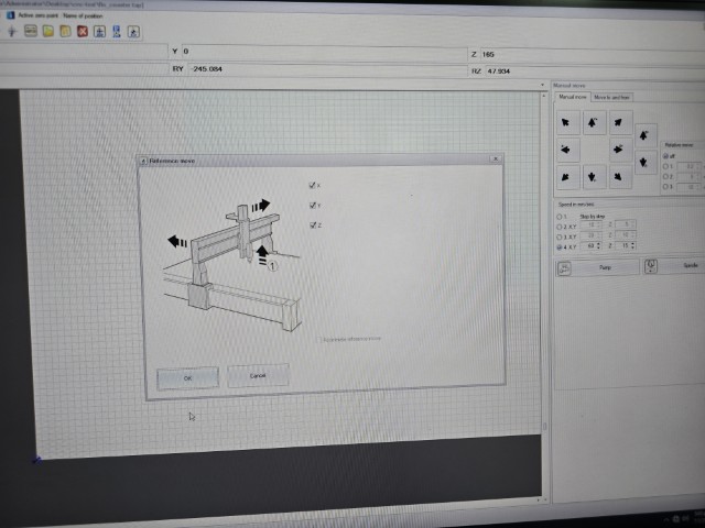
• Set zero point for sacrificial board - To let the machine know the start point of the sacrificial board. The sacrificial board is used to protect the machine bed.
• Measure tool length using the tool probe sensor - This is to calibrate the tool so that the relationship between the tool and the work surface is known (e.g. how far down to cut).
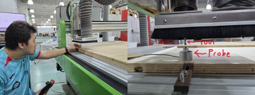
• Place the stock and fixture it to the sacrificial board - This is done to securely fasten the stock securely so that cutting can be done safely. We do this by securing the stock using screws.
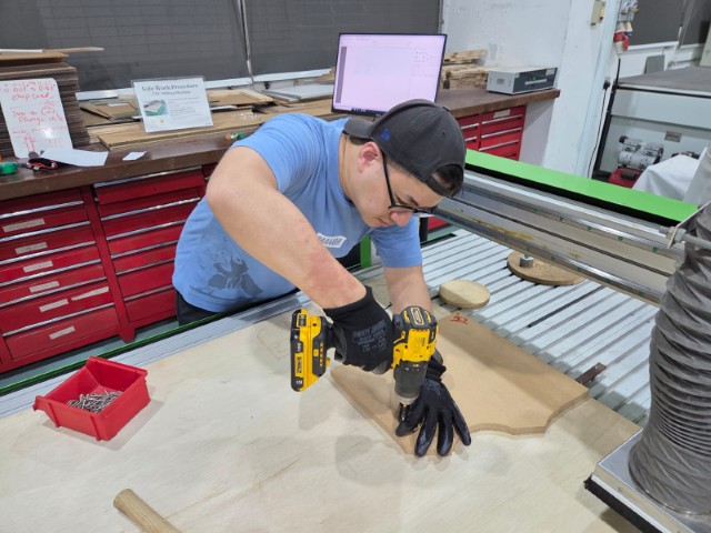
• Measure tool length using the tool sensor – Similar to the process with the sacrificial board this time this measurement is to account for the thickness of the stock.
• Set Ref X and Ref Y – Set the origin point for the cut using the controller.
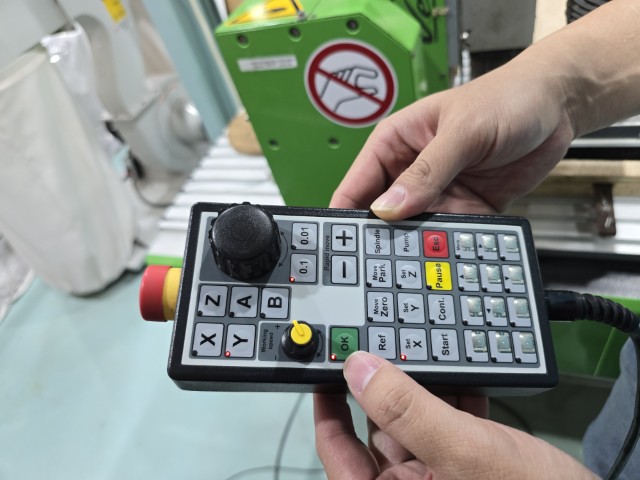
• Start cut - Once all the settings have been applied correctly, press start to begin machining.
CNC Tests
For our tests we milled out C-shaped channels at different feed rates.
In CNC machining, "feed" refers to the rate at which a cutting tool moves across the workpiece, and "load" essentially represents the amount of material being removed per tooth of the tool, meaning a higher feed rate directly translates to a higher load on the cutting tool; essentially, the faster the feed, the greater the load placed on the tool as it cuts more material per unit time.
Key points about the relationship between feed and load:
• Chip load: The key metric connecting feed and load is "chip load," which is the thickness of material removed by each cutting edge per revolution.
• Higher feed, higher load: Increasing the feed rate while keeping other parameters constant results in a larger chip load, meaning a higher load on the tool.
• Impact on tool wear: Excessive load due to a high feed rate can lead to faster tool wear and potential tool failure.
• Surface finish: Conversely, a lower feed rate generally leads to a better surface finish but may also decrease material removal rate.
Formula for Chip load
Chip load = Feed rate (mm per minute) / (RPM x number of flutes)
Chip load range: Between 0.025mm to 0.25mm.
Feed Rates | Chip Loads Tested
| Feed Rate (mm/min) | Chip Load (mm) |
|---|---|
| 3000 | 0.0625 |
| 4000 | 0.833 |
| 5000 | 0.1042 |
| 6000 | 0.125 |
Materials Used
Material A: Plywood - 14.5mm
Material B: MDF - 15.7mm
Constant Settings
Spindle speed constant at 12000RPM using a 4 flute endmill, with a plunge rate of 600 mm/min.
Results
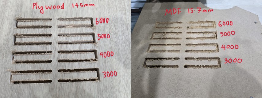
We observed that the higher the feed rates, the rate of material removal increased. While we expected a more pronounced difference in surface finishing (higher feed rate = worse surface finish), this is not what we saw. After vacuuming up the chips, we found that there was not really much difference between the 3000 and 6000 mm/min feed rates. We think that this is because all the chip loads we tested were all within the recommended range of 0.025mm to 0.25mm, so there was not much difference in surface finish. We also observed that the plywood chips tend to be “stringier” than those of the MDF.
Lastly, we also measured the toolpath and found it to be approximately 6mm, which is the same diameter as the end mill, meaning that the runoff and kerf of the milling process is minimal.
Fitting
To test fitting, we initially used a 2-flute end mill on our 14.5mm plywood that produced a terrible test comb as shown below. We think this could be due to the end mill being blunt.
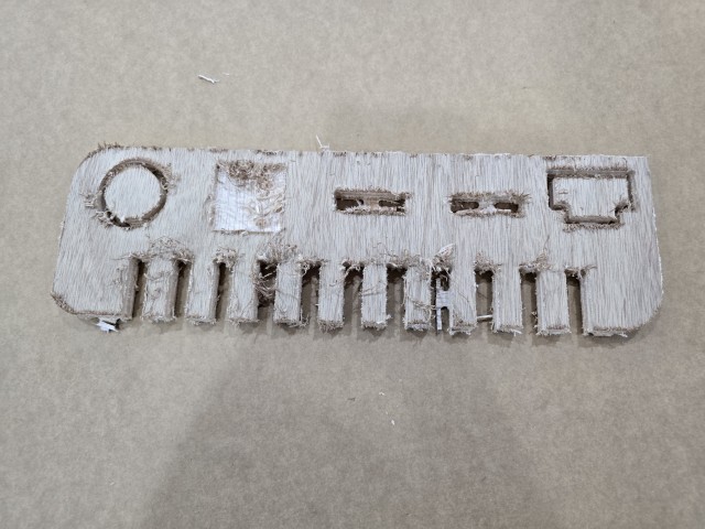
As such, we had to change the end mill and redo our test. This time we used a 4-flute end mill and produced a better result.
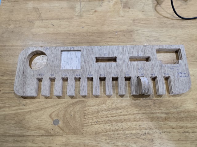
We found that we get a good fit with using the 14.8mm gap value with the 14.5mm material thickness.
We messed up our tests with fits (with and without the dog bone) because we got the size of the male piece wrong on our sketch. However, we understand that the dog bone corner is required because the end mill is round and cannot cut perfect 90 degree inside corners.
Bending
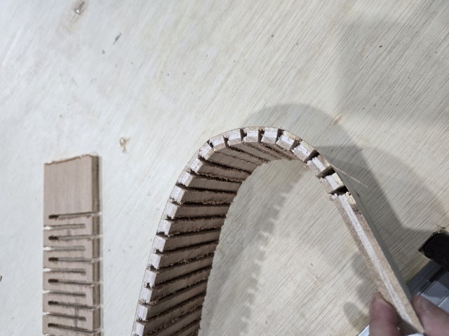
We tried to create flexible curved cuts with a plywood board that we measured to be 11.8mm thick. We successfully created bendable cuts as shown in the image and video below. For one, tne was cut path of the bending part was cut through entirely, while the other was bent using a series of half-cuts.
This concludes the Group Assignment for Week 07.
