Week 07: Computer-Controlled Machining
During Week 7, the group assignment entails conducting the safety training test for our laboratory, focusing on runout, alignment, speeds, feeds, materials, and toolpaths relevant to our CNC machine.
Computer-Controlled Machining
Computer-controlled machining, commonly referred to as CNC (Computer Numerical Control) machining, is a highly accurate and automated manufacturing process that utilizes computer systems to control and operate machine tools. CNC programs containing detailed instructions for tool paths, feed rates, and cutting parameters are executed by the computer to precisely guide the machining operations. CNC machines, such as CNC mills, lathes, routers, and grinders, can produce complex parts with exceptional accuracy and repeatability, enabling efficient and flexible manufacturing across various industries, including aerospace, automotive, medical, and consumer products.
Definitions for this week
CNC: Computer Numerical Control
End Mill: A cutting bit used for milling
Flute: A channel on an end mill to direct the cutting debris
Runout: When the End Mill doesn’t spin perfectly on its center axis, it wobbles and results in runout
Spoil Board: The board on top of the machine bed that is made to protect the bed from the end mill cutting through your material
Alignment: Levelness and straightness of the spoil board
Fixturing: How we hold the material to be cut on the bed
Toolpath: The path that the endmill follows to cut the material
Tabs: Small Sections of Material that the machine avoids to hold material in place when cutting through the entire thickness of stock
Safety and precautions
-
Safety Training Importance: Safety training plays a vital role in creating awareness and promoting a culture of safety in any workplace. It equips individuals with the knowledge and skills necessary to identify hazards, assess risks, and implement preventive measures to ensure a safe working environment for everyone involved.
-
Hazard Identification Process: Hazard identification involves systematically identifying potential sources of harm or danger within the workplace. This process may include:
- Regular inspections of the workplace to identify existing or potential hazards.
- Reviewing incident reports and near-miss incidents to identify recurring hazards or patterns.
- Consulting with workers and employees who are directly involved in the tasks to identify hazards specific to their work areas.
-
Utilizing hazard identification tools such as checklists, risk assessments, and safety audits to comprehensively identify hazards.
-
Risk Assessment: Once hazards are identified, the next step is to assess the associated risks. Risk assessment involves evaluating the likelihood and severity of potential harm resulting from exposure to hazards. This assessment helps prioritize hazards based on their level of risk and guides the development of control measures to mitigate or eliminate these risks.
-
Control Measures: After assessing risks, control measures are implemented to manage hazards effectively. Control measures can include:
- Engineering controls: Modifying the workplace or equipment to minimize exposure to hazards (e.g., installing machine guards, ventilation systems).
- Administrative controls: Implementing policies, procedures, and training programs to reduce exposure to hazards (e.g., establishing safe work practices, providing safety training).
-
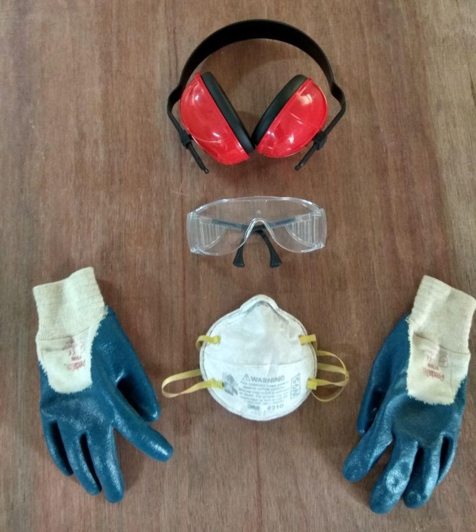
Personal protective equipment (PPE): Providing suitable PPE to workers to minimize the risk of injury or illness (e.g., safety goggles, gloves, earplugs).
-
Continuous Improvement: Safety is an ongoing process that requires continuous monitoring and improvement. Regular review of hazard controls, incident investigations, and feedback from workers can help identify areas for improvement and ensure that safety measures remain effective over time.
By prioritizing safety training, hazard identification, risk assessment, and effective control measures, organizations can create a safer and healthier work environment for everyone involved. Certainly, here are safety measures to consider when operating a ShopBot CNC Router:
-
Read the Manual: Familiarizing with the manufacturer’s instruction manual for the specific model of ShopBot CNC Router being used. This manual provides essential safety information, operating procedures, and maintenance guidelines.you can find the manual here.
-
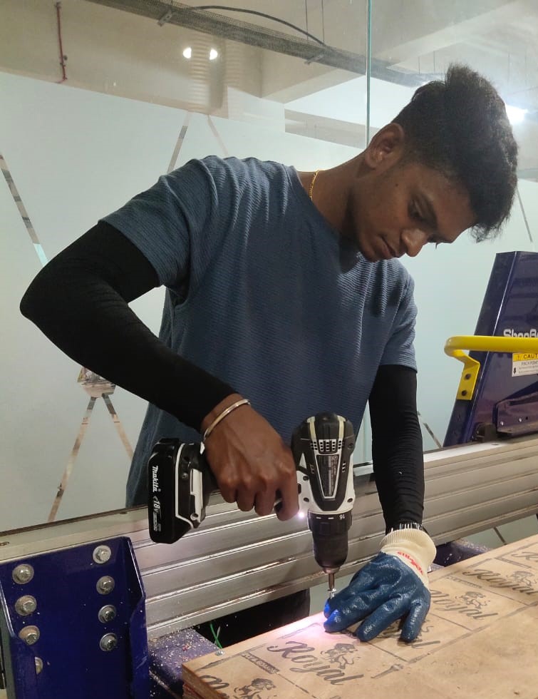
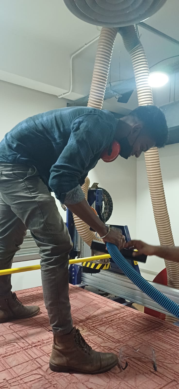
Personal Protective Equipment (PPE): Wear appropriate PPE, including safety glasses, hearing protection, and enclosed footwear, when operating the ShopBot CNC Router.
-
Material Handling: Use caution when loading materials onto the CNC Router bed. Secure materials properly to prevent movement during machining operations, and never place hands or body parts near moving components.
-
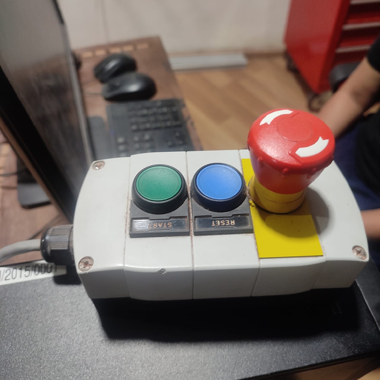
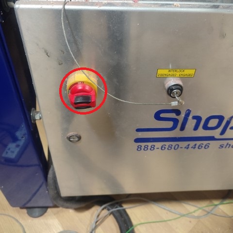
Emergency Stop: Familiarize yourself with the location and operation of the emergency stop button on the ShopBot CNC Router. In the event of an emergency or unexpected situation, immediately press the emergency stop button to halt machine operation.
-
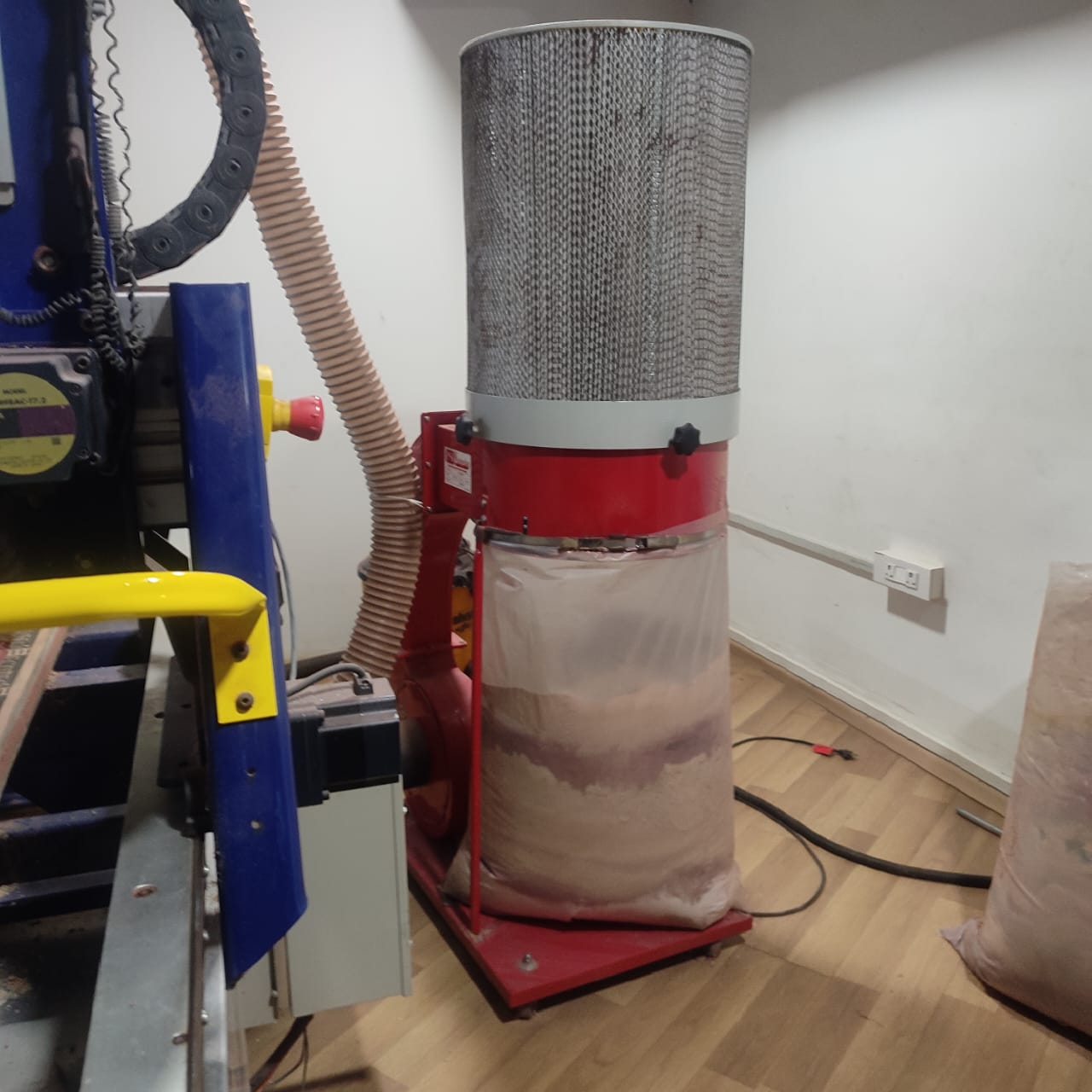
Dust Collection: Utilize appropriate dust collection systems to control airborne particles generated during machining operations. Minimize the accumulation of dust and debris in the work area to prevent potential hazards and maintain a clean working environment.
By adhering to these safety measures, we can minimize the risk of accidents and injuries when operating a ShopBot CNC Router, ensuring a safe working environment for themselves and others.
Test piece design
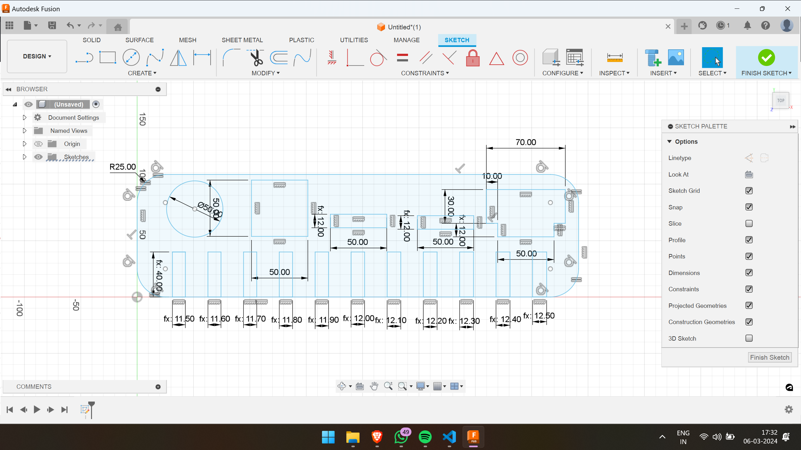 Features provided:
1. Pocket(r-30mm)
2. profile cut(r-30mm, 6060mm)
3. 12 slots of thickness ranging from 10.5mm to 13.8mm
4. Rectangular slot with and without dogbone (5012mm)
5. Test fit piece
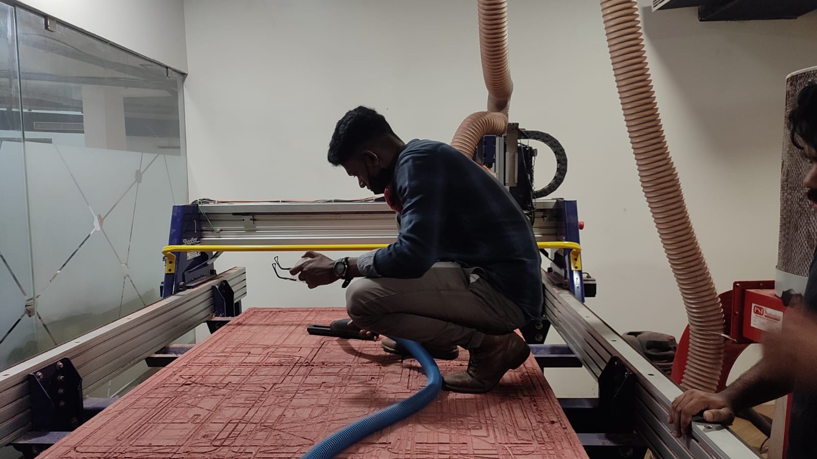
ShopBot PRSalpha 96 CNC Router
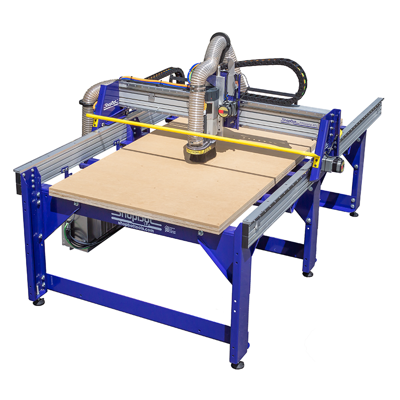 This is the CNC machine that we have in our lab. ShopBot It is designed for precision cutting, carving and machining.
Features of the machine:
• Bed is stationary
• Spindle moves in X,Y,Z directions
• Bed size: 1.7526m x 2.4384m
• Table Thickness: ¾” Plywood Bottom Layer, ¾” MDF Top Layer
 .As the CAM is completed we can open the ShopBot’s Software to load the CAM toolpath and run the files
CAM Toolpath 
Drill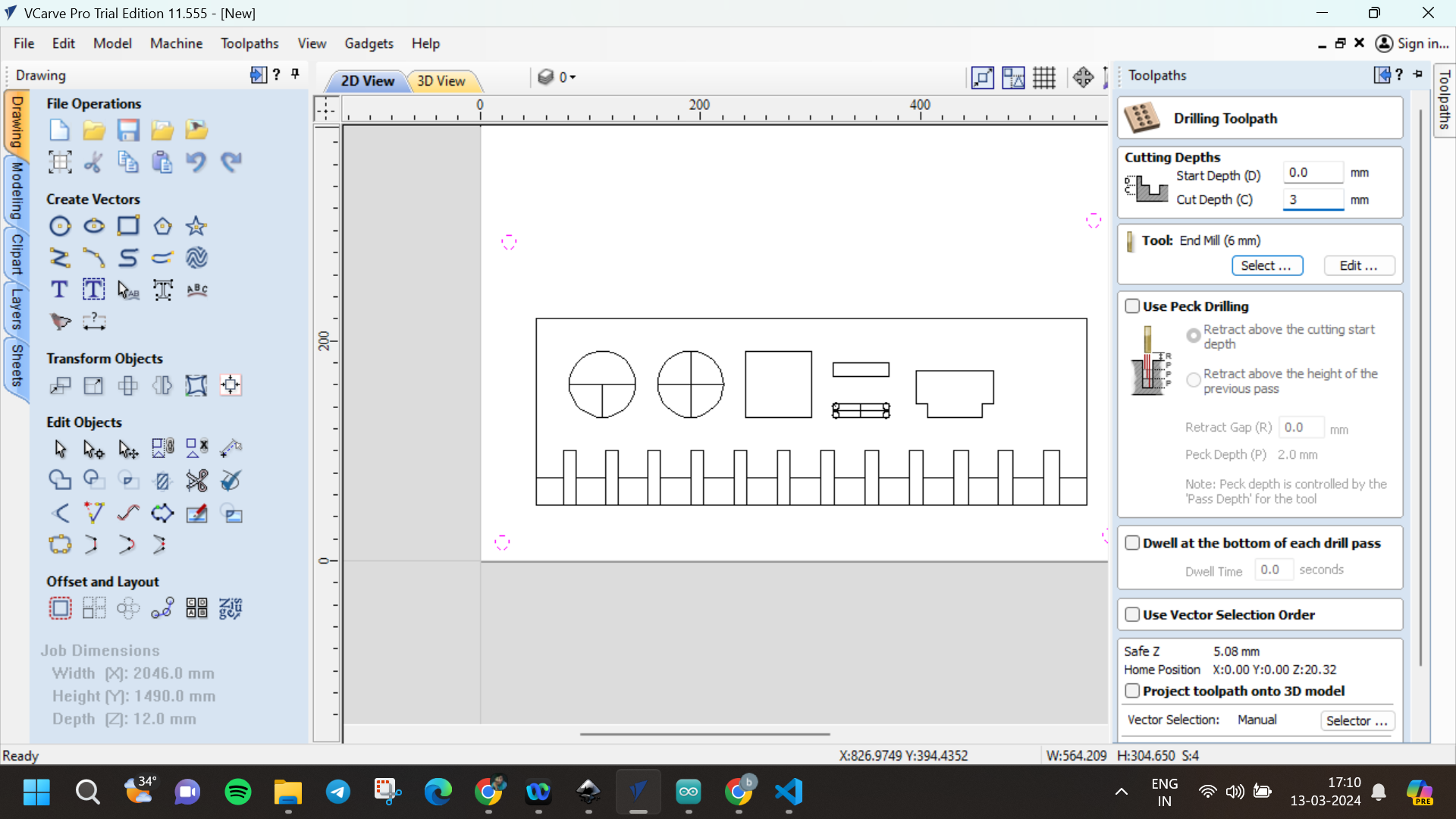
Pocket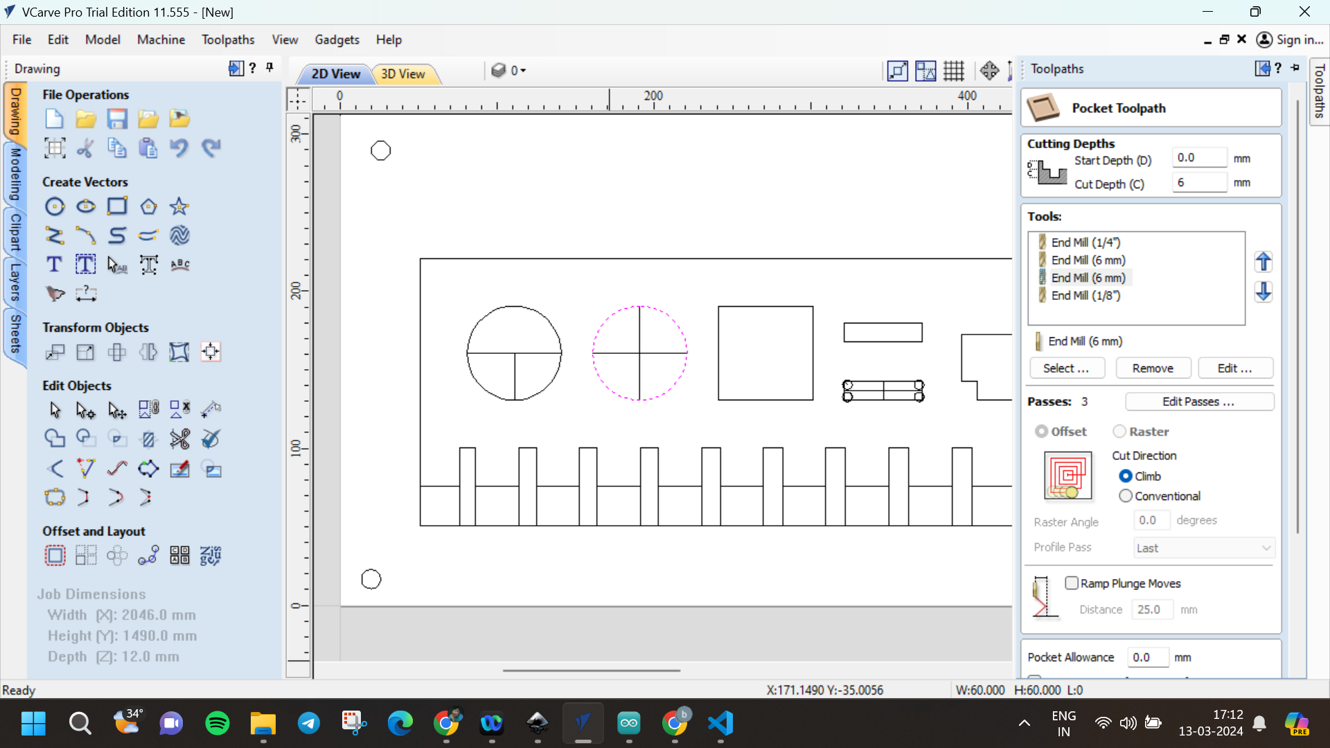
Inner profile cut
Outer profile cut
• Our first step involved thoroughly
cleaning the machine bed to ensure optimal working conditions. By removing debris and residue, we aimed to create a
surface conducive to precise machining operations.
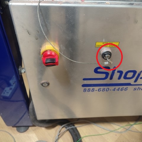
• The next step involves activating the ShopBot by rotating the knob situated on the side panel of the machine.
• Prior to initiating the cutting process, it is crucial to secure the plywood sheets onto the ShopBot platform using screws to prevent any unwanted movement during operation.
• Upon powering on the ShopBot, the next step is to launch the ShopBot3 software
.

• The next step involves setting the origin. To achieve this, operators can jog the module along the X and Y axes to establish the zero position. As for the Z axis, the machine is equipped with a plate and an alligator clip. Positioning the clip and the metal plate to make contact triggers the machine to automatically set the zero position for the Z axis.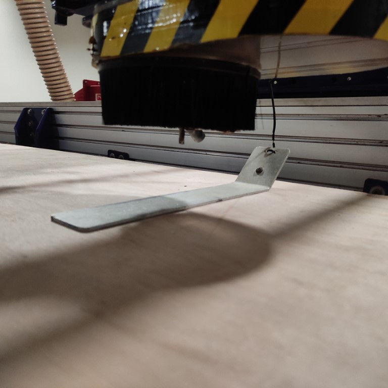
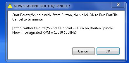
• Once all three axes are zeroed, proceed by selecting “Cut Part” to upload the file. Then, click on “Start” button on the remote. Subsequently, a pop-up box will appear prompting you to switch on the spindle. To do so, simply turn the key located on the side panel of the machine once.
 • Now, press the “Start” button on the remote. Once the spindle begins spinning, click “OK” on the dialogue box.
Result
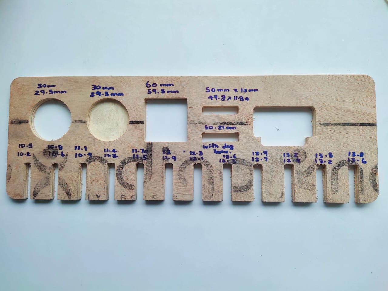
The key perfectly fits in the bigger ‘11.7 mm’ slot with a good press fit.Actually it must be tight in the slot but then we found out that the thickness of the plywood is varying due to humidity and temperature.