Week 02 - COMPUTER-AIDED-DESIGN
WEEK02 - ASSIGNMENTS
1. Model (raster, vector, 2D, 3D, render, animate, simulate, ...) a possible final project
2. Compress your images and videos
3. Post a description with your design files on your class page
For this week’s assignment, I have decided to explore 3D modelling workflows with 2 different types of CAD software:
• 3Ds Max – Polygon modelling software. I have used 3Ds Max in the past previously, and while I am a bit rusty, this is still the CAD software that I am most comfortable with.
• Fusion 360 – While I have used Fusion 360 in the past, I have not explored it extensively. Moreover, Professor Neil mentioned that learning about constraints and parametric modelling is going to be important in Fab Academy, which is why I decided to try Fusion 360.
3Ds Max
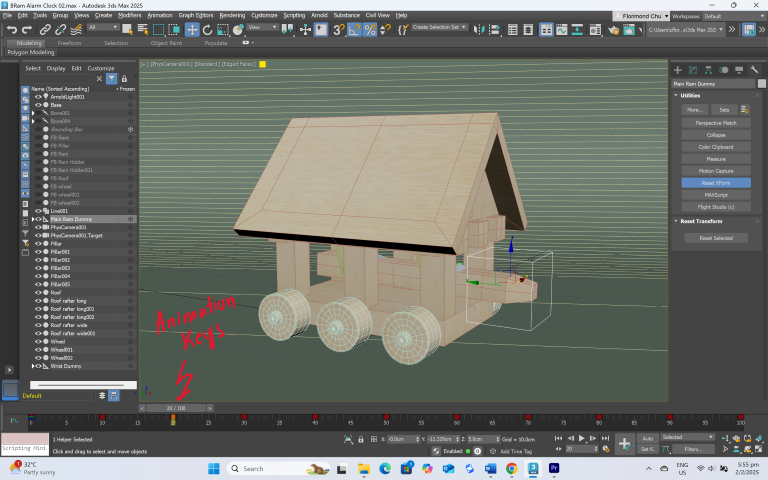
Modelling
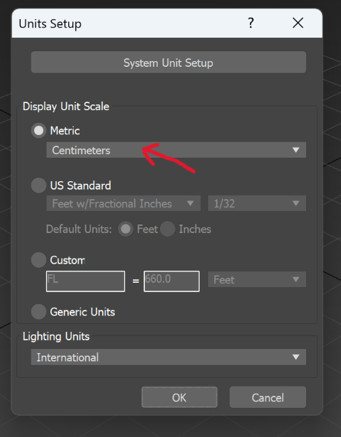
• Units set-up – First, I set up the units of the scene to match the scale of the object I am modelling.
• Create a bounding box – I create a bounding box of dimensions 20cm x 15cm x 15cm (L x W x H). This is done so that when I am modelling, I can roughly know how big or small something is in relation to the bounding box.
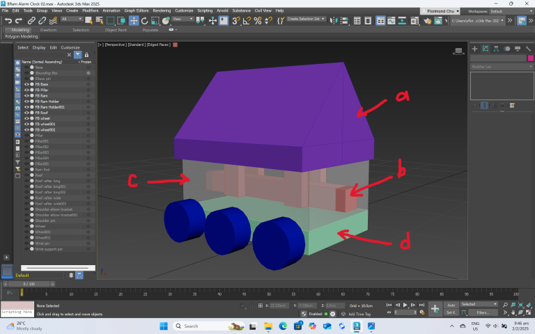
• Form blocking – Next, I lay down some primitives (cubes and some cylinders), convert them to editable polys, and then start creating the basic forms of my model. This also helps me to determine the main parts of my model:
a. Roof – Houses the clock and most of the electronic components
b. Ramming mechanism – Hung from the roof
c. Pillars – Holds up the roof
d. Wheeled base – Foundation of the structure
• Detailing – Once I am happy with the form block, I go in and model each of the different parts. Here is how I created each of the elements:
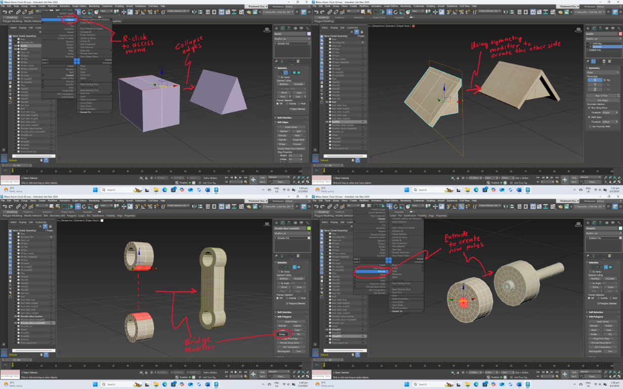
a. Roof – Cube primitive > Convert to Editable Poly > Collapse top edges to create triangular shape > Extrude the main roof surface > Extrude the overhangs > Delete the incomplete half and use symmetry to mirror over the completed half.
b. Ramming mechanism
o Ram Rod – Cube primitive > Convert to Editable Poly > Extrude the ram head > Taper the ram head by scaling the polygons on the tip
o Ram Support Brackets – Cylinder primitive > Convert to Editable Poly > Duplicate the Cylinder and move it to the right position below the first > Attach it to the first Cylinder > Connect the first and second Cylinders by selecting polys and bridging them to form the “spanner” shape of the bracket > Use symmetry to mirror the bracket so that it forms a pair > Duplicate the bracket pair to get another – there are 2 bracket pairs holding up the Ram Rod
o Ram Pins – These are just cylinder primitives
o Pillars – These are just cube primitives
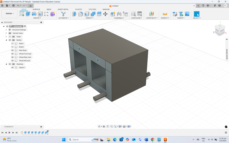
c. Wheeled base
o Base – This is a cube primitive
o Wheels – Cylinder primitive > Convert to Editable Poly > Delete the end caps > Select the open edge border > Use “shift-drag” to create new polygon to close the formerly deleted caps > weld the vertices so that there is only one vertex at the centre of the wheel > connect the edges radiating out from the central vertex – the new edges will define the hub and axel of the wheel > Select the polys that define the hub and axel to form the geometry for the hub and axel.
Some other useful poly modelling techniques
Shift-drag – Create new polygons by selecting an edge from existing geometry and then holding shift while dragging. This makes it easy to create new polygons as the movement is quite intuitive (like a brush stroke)
Connect – I use this function a lot to subdivide a polygon into smaller evenly-spaced polygons.
Coordinate Display – This is very useful in placing objects accurately in the scene. Instead of just “eyeballing” it you can type in the exact coordinates of where you want an item to be.
Texturing
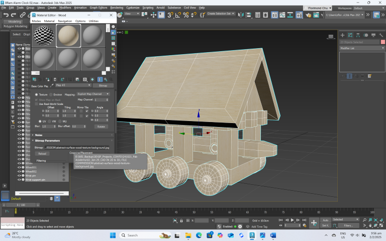
• UVW Map – This is the process of applying “wallpaper” to your model. The UVW Map is a quick way to do this. I applied a simple wood texture to the entire model.
Rigging
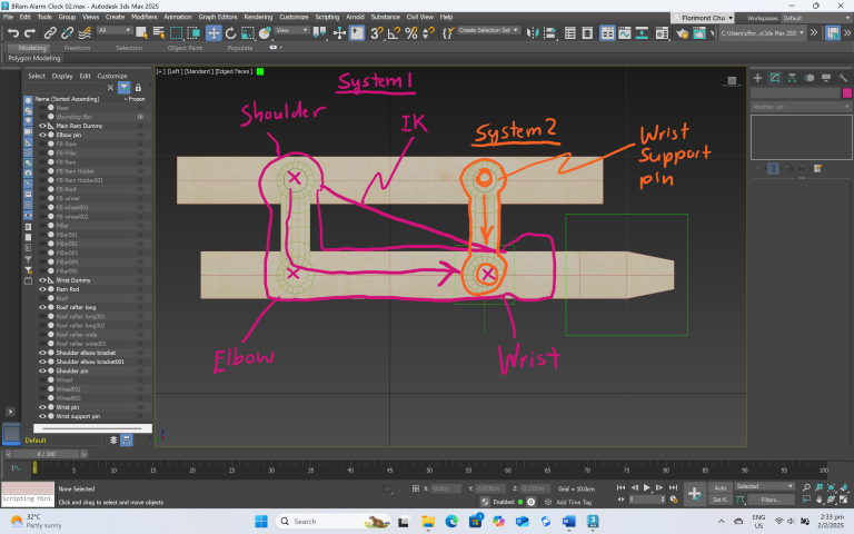
As shown in the diagram below, I am planning a simple rig to drive my ram through one control. To make it easy to understand, I look at the ram like an arm with a secondary support at the wrist.
I am not very familiar with the rigging pipeline and I am thankful for this YouTube video by Lee Minardi to help me through it.
Basic rigging workflow:
• Make sure the pivots are in the right place
• Lay down the bones.
• Put in the IK solver (Animation > HI Solver)
• Link the geometry/dummies to the bones
• Test
Animation
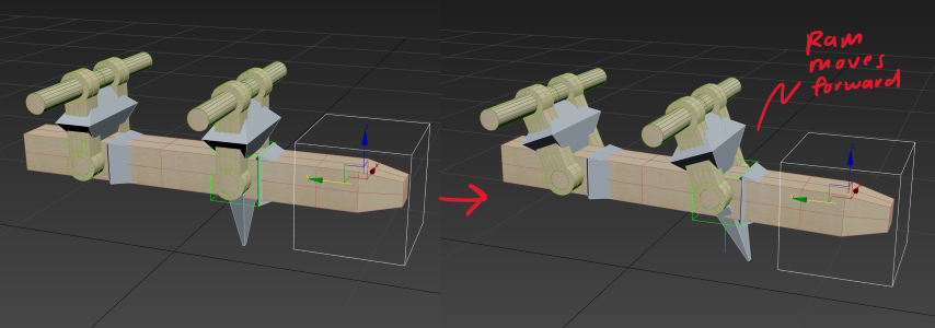
I created a simple animation of the ram action by moving the slider on the animation timeline and setting keys for the following poses:
• Pose 1 – Ram moves back
• Pose 2 – Ram moves forward
I then copy over these pose keys to create a repeating ramming action.
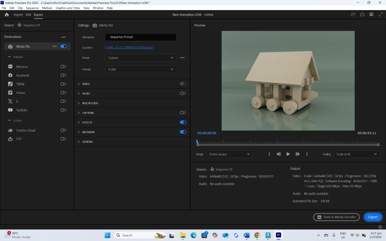
Rendering and Video Compression
For the render, I used Arnold to render an image and a video. I referred to this YouTube video by Man and Machine Ltd for the basics on how to use the Arnold renderer.
END RESULT - 3DS MAX RENDER

After I rendered the video, it was still too large at 1.83MB (for Fab Academy standards). I thus brought it into Adobe Premiere Pro to compress it to 368KB.
Fusion 360
I found these online Youtube tutorials from Product Design Online very useful in understanding the workflow of Fusion 360 and will highly recommend these to anyone wanting to learn Fusion 360.
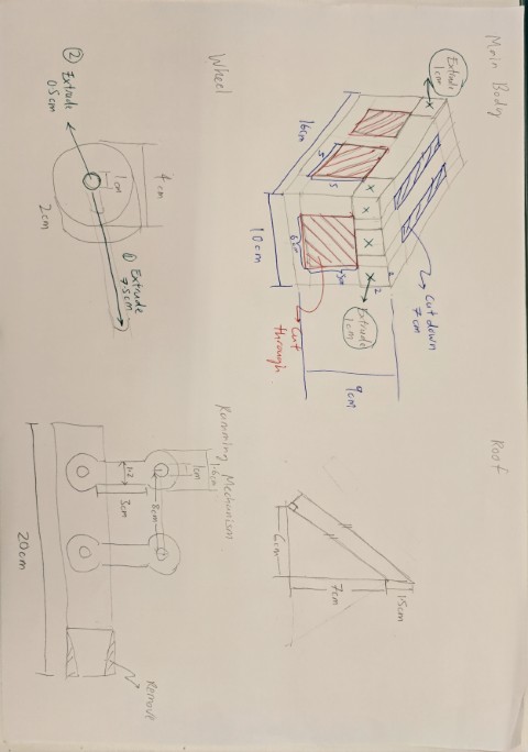
Sketch Plan
I start my Fusion 360 CAD exploration by attempting to build the 3D model that I had previously completed in 3Ds Max. Before even starting up Fusion 360, I create a paper sketch to help me think through how I should go about creating the various forms of the model, and the sketch dimensions.
Modelling
Fusion 360 is all about creating sketches and then manipulating them to create shapes. I start by drawing the side profile sketch.
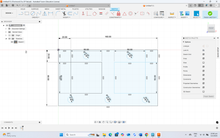
By extruding the appropriate parts of the sketch, I create the main body of the model.
It is also possible to remove parts of the model by defining the extrusion as a cut-out.
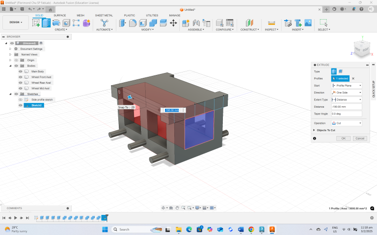
Using “sketch-followed-by-extrusions”, I create the wheels of the model.
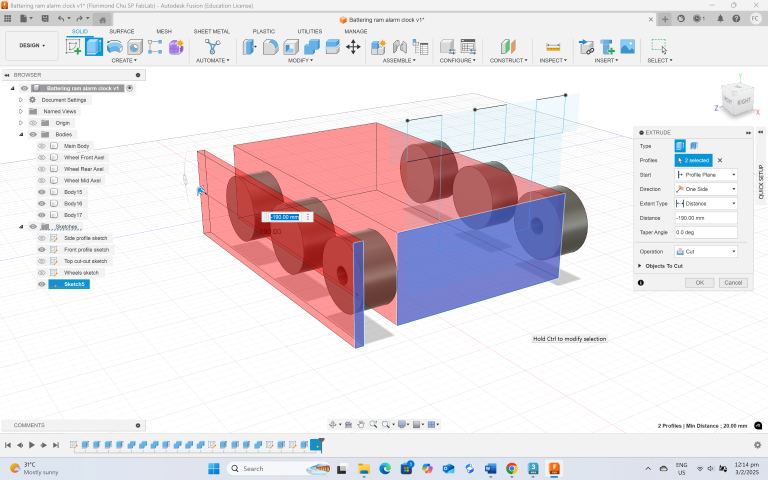
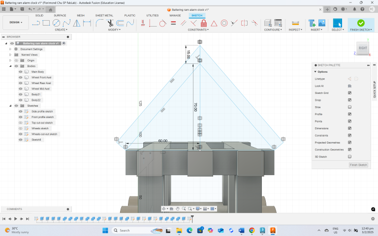
Similarly, I sketch out the roof. I came across the sketch symmetry option and it was useful in helping me mirror the sketch. This way, I only had to define the dimensions on one side of the sketch, and then it will be mirrored over to create the other half.
I apply similar techniques to create the ram mechanism.
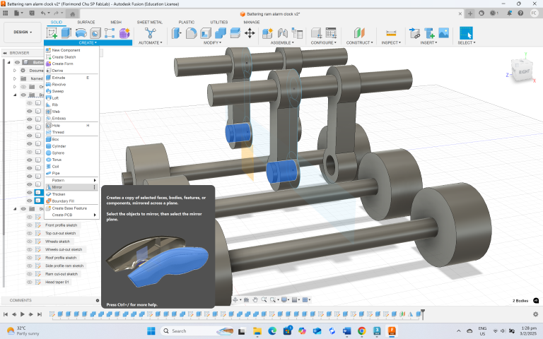
Lastly, I added some fillets to improve the model.
Texturing
Fusion 360 has a material library, and I applied a wood material from the material library to the model.
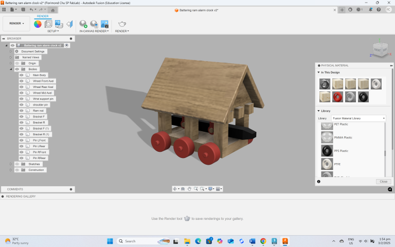
Rendering
Fusion 360 comes with some preset scenes to help with the final render. I applied soft lighting to the scene, then rendered out a still image. This ends my exploration of Fusion 360.
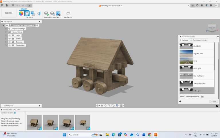
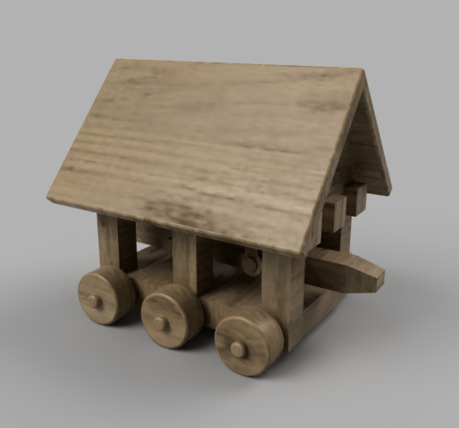
End Result - Fusion 360 Render
3Ds Max VS Fusion 360
Having explored both 3Ds Max and Fusion 360, my thoughts are:
• 3Ds Max is good for quickly creating models that just look right but do not need to be fabricated. This is especially true for organic forms. It could be great for mocking up ideas just to see how they look. This is because with polygon modelling, you do not really need to know the exact dimensions of the final product to achieve a decent model.
• As the key workflow of Fusion 360 involves thinking about the dimensions, it forces the designer to think more deeply about their design intent. I would say that I would use Fusion 360 if I need to produce things that require dimensional accuracy. The parametric nature of Fusion 360 also allows me to make adjustments without having to re-model the object. In conclusion, I would use both CAD packages depending on the requirements of the model. If it just needs to be virtually represented, I will use 3Ds Max. If it needs to be dimensionally accurate (such as for digital fabrication), I will use Fusion 360.
CAD MODEL Files
File Compression – Images and Video
A constant thing that all Fab Academy students need to do is to keep their file sizes small (each commit should be 10MB or less). As such this how I keep my file sizes small:
Image Compression
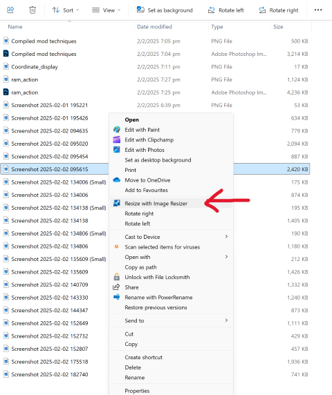
For images, I use Power Toys to reduce the file size by following these steps:
• Download Power Toys from the Microsoft Store (It is a free app)
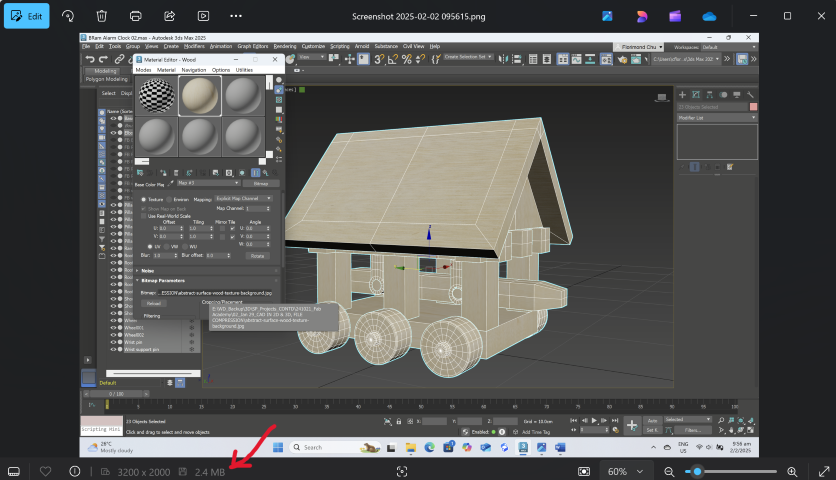
• Select the image that has a large file size. In this case, I have chosen a 2.4MB screenshot image to reduce in size
• In the File Explorer, right click the image and when the menu appears, select the option “Resize with Image Resizer”.
• Next, choose an appropriate image size to reduce to, and then select “Resize”
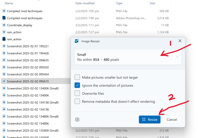
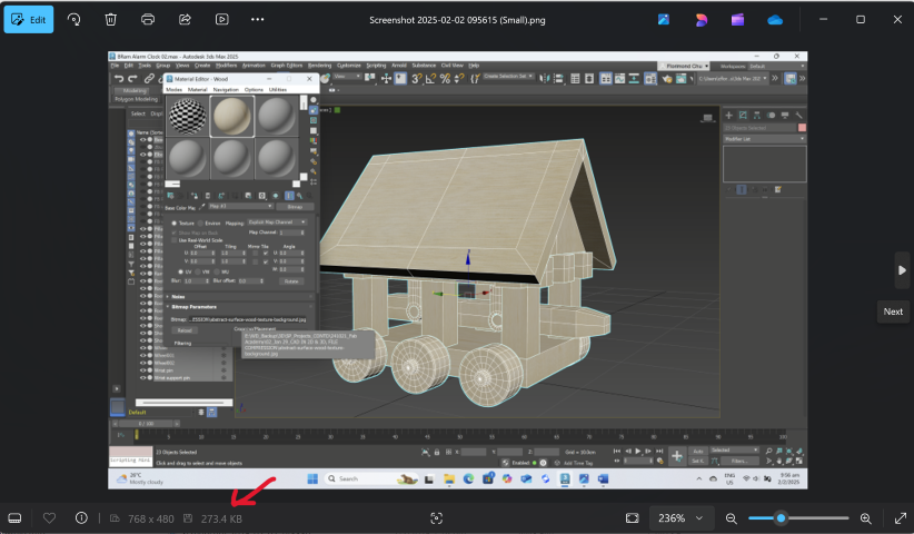
• By using this tool, the image size has now shrunk down to 273.4KB (From 2.4MB)
Video Compression
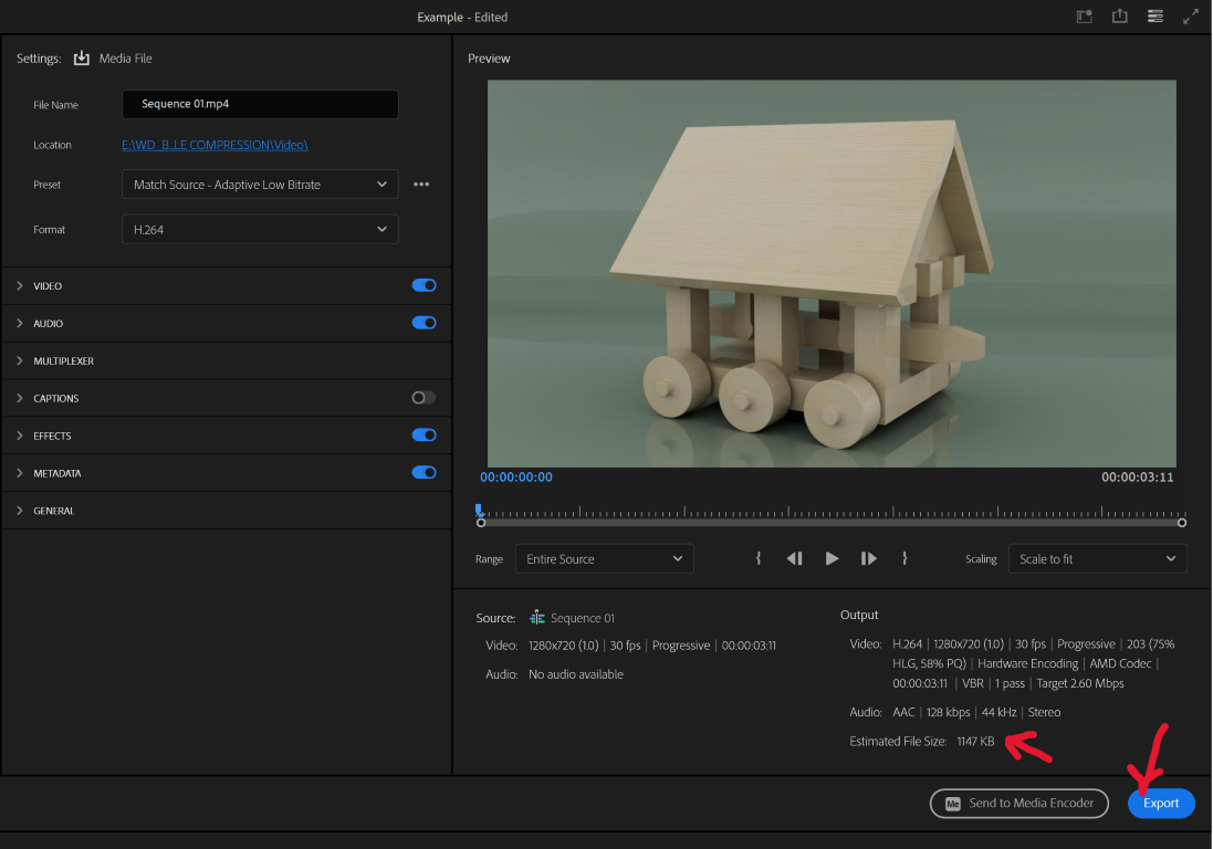
For video, I brought my video into Adobe Premiere Pro to reduce the file size. Here are the steps:
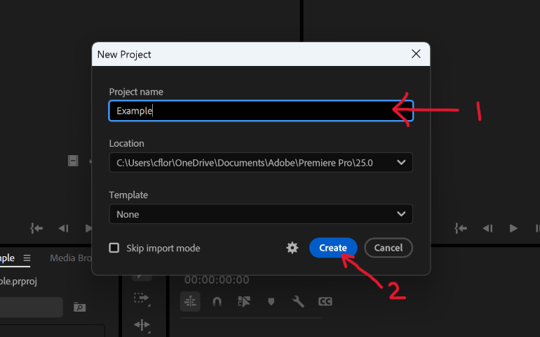
• Open Premiere Pro and click on “New Project”
• Enter your project name, and then click “Create”
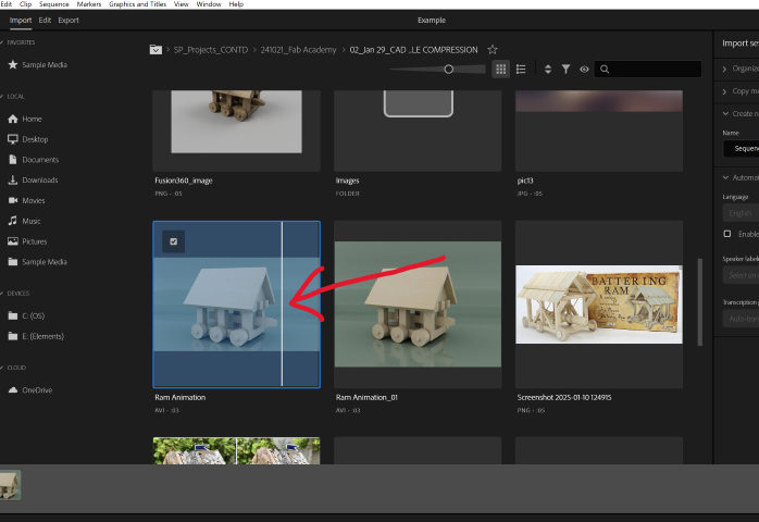
• Next, import the video. Choose the video you want to downsize. For this example, I selected a video of my ram’s animation that is currently around 3MB.
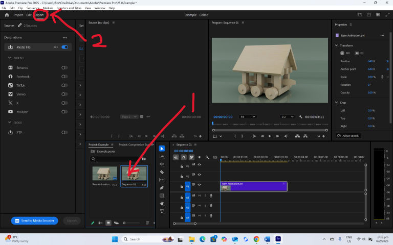
• Once in, select the video and click “Export”. This will bring you to some settings that you can use to reduce the video file size.
• Change the video setting preset to “Match Source - Adaptive Low Bitrate”
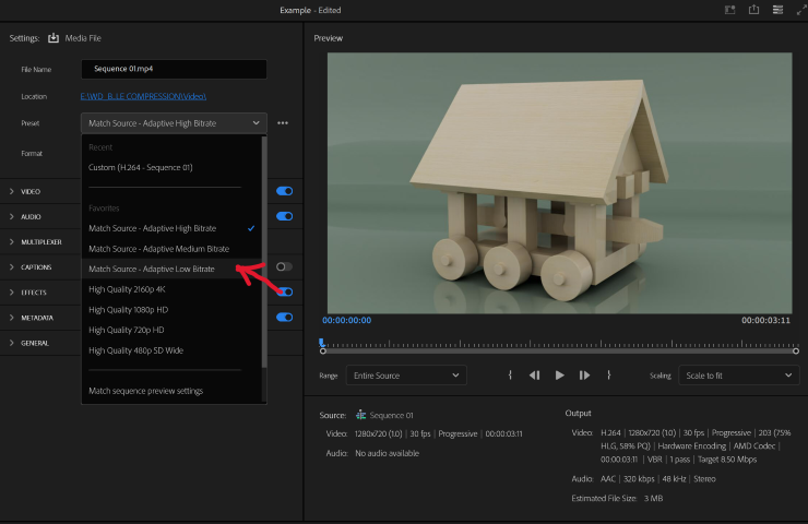
• The video now becomes around 1MB in size. Click “Export” to save your new smaller-sized video
With these compression tools, you can now keep your media files small.
2D Software
For 2D software, I explore:
• Raster – Adobe Photoshop 2025
• Vector – CorelDraw Standard 2021
Adobe Photoshop 2025
In this exploration, I first used Photoshop to create a stylized drawing of a snake using a photograph as a reference layer.
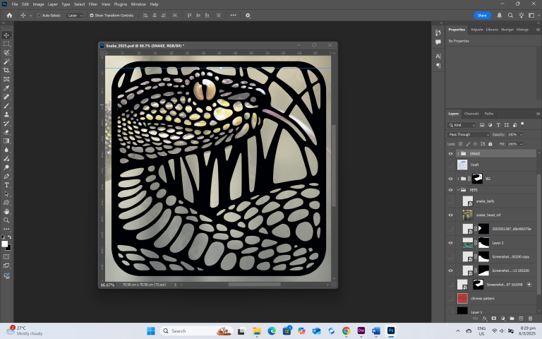
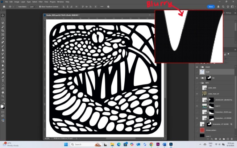
I did this drawing mainly using tools such as the Brush tools and Pen tools. The Brush tool paints in pixels, while the Pen tool creates a editable path that can be used for different drawing functions such as a path to apply a brush stroke, or as an outline to be filled with colour. The Pen tool functions are in some way similar to those found in a vector 2D software, but when you zoom in, you can see that the image is composed of pixels. This is why when raster images (such as jpegs) are displayed bigger than their intended resolution, they look jagged and blurry.
I export the image as a 2000 x 2000 PNG for the next step of my exploration.
CorelDraw Standard 2021
I start this section by importing the PNG into the CorelDraw workspace. I then use the Trace Bitmap function to convert the PNG into vector curves.
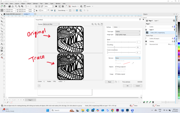
Unlike a raster image, a vector image does not lose resolution because the image is defined by the direction of the vector, rather than pixels.
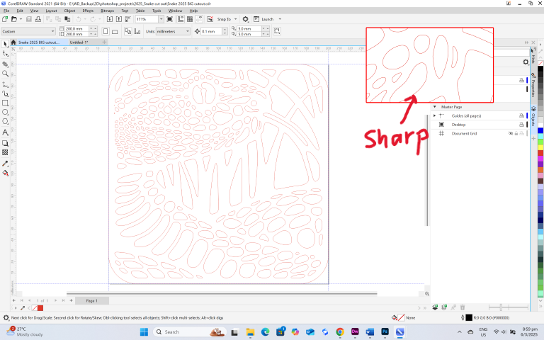
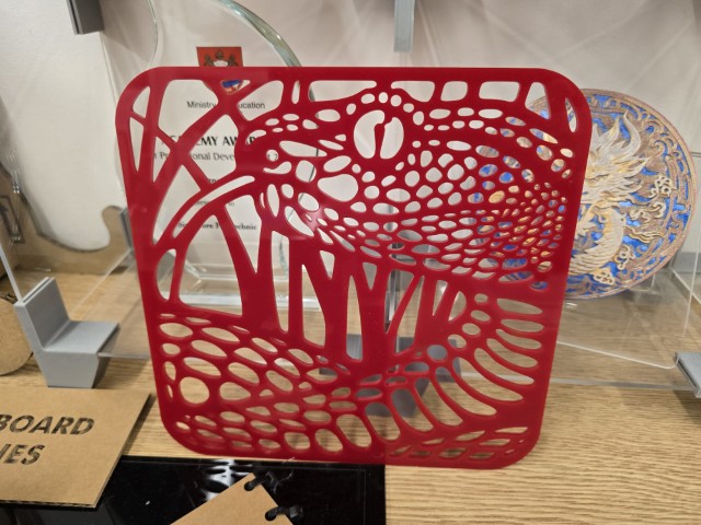
Vector software such as CorelDraw can also be used to create SVG files for laser cutting, which is what I did to create this snake cut out.
This exploration on 2D concludes my documentation for this week.