Week 05 -3D Scanning and Printing

Group assignment:
• Test the design rules for your 3D printer(s)
Individual assignment:
• Design and 3D print an object (small, few cm3, limited by printer time) that could not be made subtractively
• 3D scan an object (and optionally print it)
Group assignment
For this week’s Group assignment, I teamed up with my fellow Fab Academy buddy Haw Ren to test the design rules for our lab’s 3D printers.
The documentation for our Group assignment can be found here.
Individual assignmenT - DESIGN AND 3D PRINT AN OBJECT THAT COULD NOT BE MADE SUBTRACTIVELY
For this assignment, I decided to create a train ornament with print-in-place (PIP) joints. Print-in-place 3D prints rely on the unique ability of additive manufacturing to create fully assembled, functional mechanisms in a single print job without requiring additional assembly.
An object with print-in-place joints cannot be made subtractively because substractive manufacturing processes cannot reach internal cavities or create enclosed mechanisms without additional assembly steps.
Creating the print-in-place ball and socket joint in Tinkercad
I use Tinkercad to create the ball and socket joint. I first create a 9.6mm diameter sphere, followed by a slightly larger 10mm diameter sphere. These will be the starting shapes to develop the Ball (Male) part and the Socket (Female) part. The parts are made by combining primitive shapes together (Group Function – Ctrl + G):
Ball part: Sphere + Cylinder + Cube
Socket part: Cube – (Sphere + Cylinder)
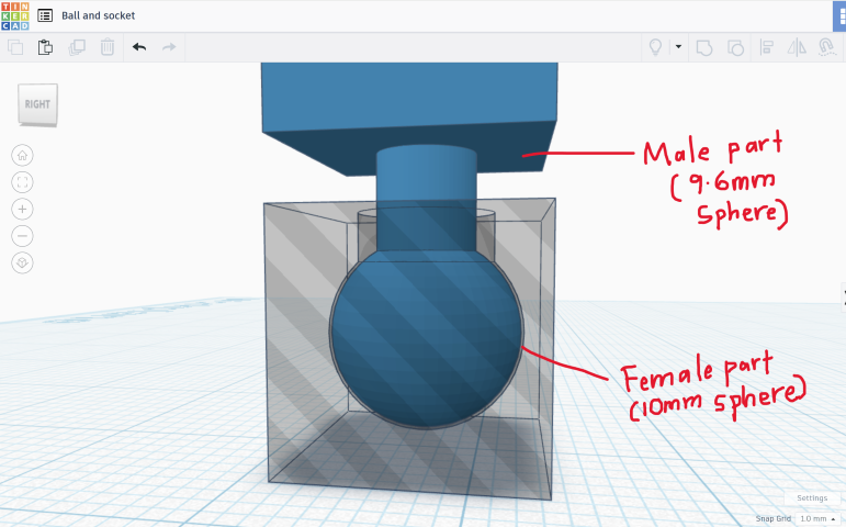
In 3D modelling, a "Boolean" refers to a set of operations that allow you to combine or manipulate multiple 3D objects by performing actions like "Union" (joining objects together), "Difference" (subtracting one object from another), or "Intersection" (keeping only the overlapping parts of objects), essentially creating complex shapes by combining simpler ones. Tinkercad is a great CAD software for performing these Boolean operations and I soon have my first test model.
I export the 3D model out, and 3D print it on my lab’s Bambu X1-Carbon 3D printer. The resulting joint works, it is not fused and can rotate without popping out. However, it has poor range of motion.
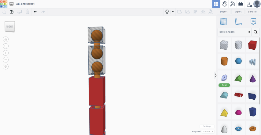
I iterated a few more times to achieve a better range of motion and found that I can get a better range of motion by creating a “dumbbell” ball joint. This is a joint with two Balls connected by a cylindrical bar, which in turn connects to the socket.
The resulting print with “dumbbell” ball joints has the best range of motion.
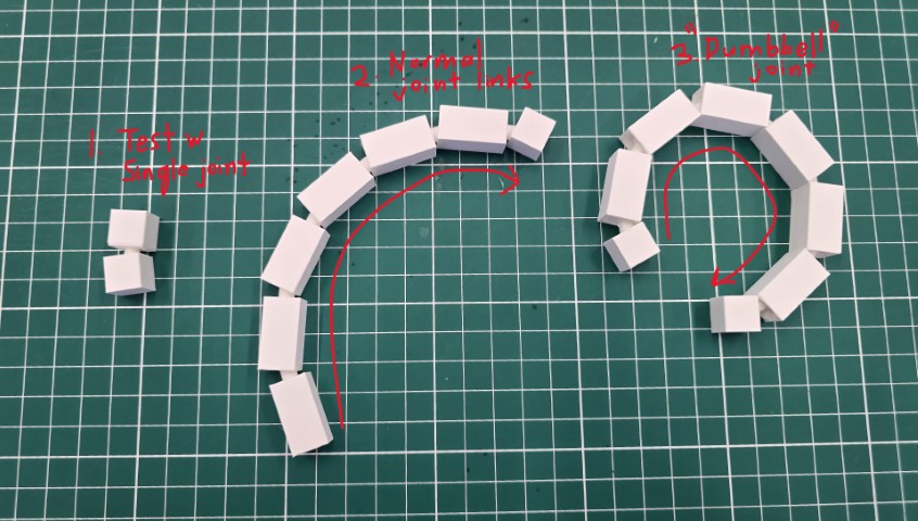
With the ball-and-socket joint resolved, I proceed to model the train.
3D Modelling the Train (3Ds Max)
Using polygon modelling techniques (see Week 02’s assignment on CAD), I used 3Ds Max to create the 3D models for the train and carriage. I chose to use 3Ds Max because:
• I can quickly generate complex geometry with the polygon modelling workflow
• The train and carriage are just aesthetic features and do not have to be dimensionally accurate to fit with other parts.

With the 3D models for the train and carriage complete, I export them out as OBJs so that I can import them into Tinkercad to combine with the ball-and-socket joints.
Combining the Train models with the ball-and-socket joints (Tinkercad)
In Tinkercad, I superimpose the train and carriage models over the ball-and-socket joint link that I have previously created. Using the “Group” function, I fuse the train and carriage models with the ball-and-socket joint link.
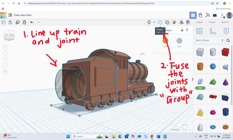
Once done, I duplicated a few more carriages to form a complete train.
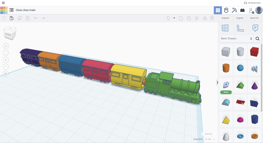
Next, I export the entire model out as an STL to print. The model is now ready to be 3D printed.
3D Printing the Train
The steps for 3D Printing with the Bambu X1-Carbon 3D printer are quite straightforward.
• Bring the file into the slicer software (Bambu Studio)
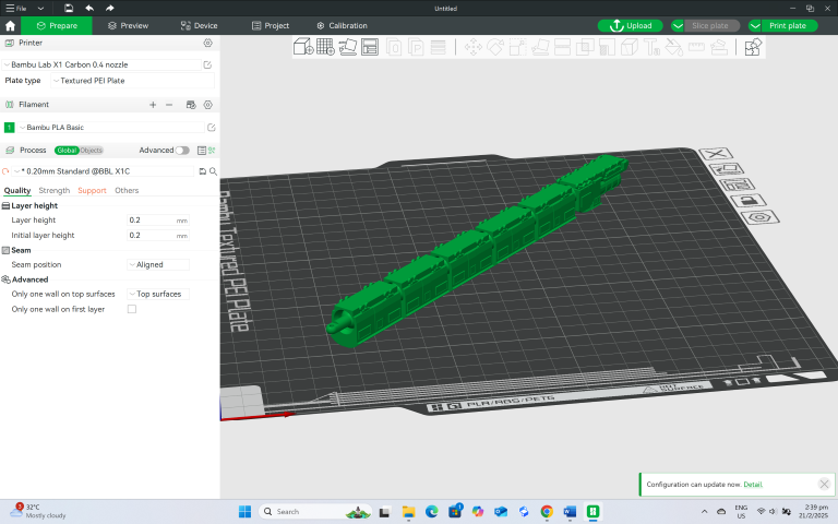
• Adjust the settings for the print. Here, I mostly used default settings, with the small adjustments:
1. Print orientation – I printed my train upside down to reduce the finishing required for the fine details at the bottom of the train.
2. Tree-like supports – Instead of using the default supports, I used tree-like supports because these are easier to remove. • When ready, select “Slice Plate” to see how long the 3D print job will take, and how much filament it will be used. Select “Print Plate” to send the g-code to the 3D printer.
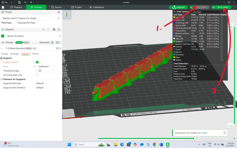
The Bambu Studio X1-Carbon 3D printer has some features that automatically help users to check certain things such as bed levelling to reduce the chance of failed prints.
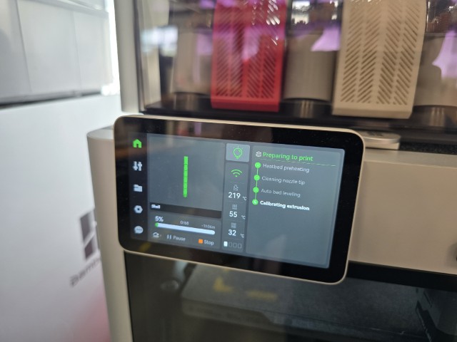
This is why, for the first few minutes, nothing seems to be extruding. But once the automatic checks are completed, the print proceeds.
After about 1 hour and 45 minutes, the print has completed. I take the 3D print out of the 3D printer.
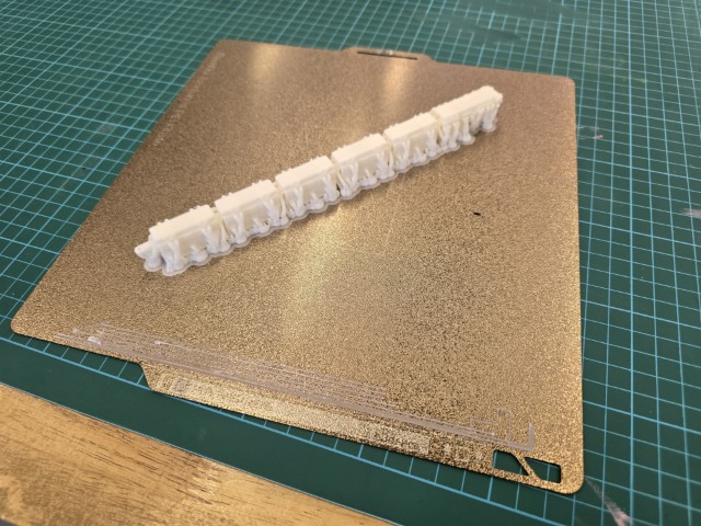
Post Processing For post processing, I simply remove the supports and use sandpaper to smoothen some of the rougher surfaces.
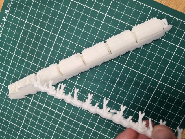
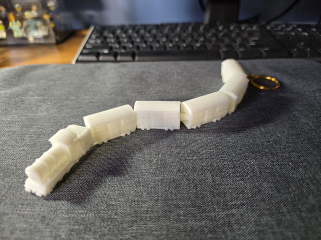
Result
As a finishing touch, I add a key ring to the train ornament to complete the project. The joints also work well, and I am happy with the way this project has turned out.
Reflection
• The print orientation of the object is important. I initially attempted to print the train upright and I realized that it was very difficult to remove the supports without damaging the delicate features of the train (such as the tiny wheels that can break off while sanding). I had much better success printing the train upside down.
• The TYPE of supports matter. For my first try, I used the default supports, and it was very difficult to remove, and I damaged some of the more delicate parts of my print. When I changed to tree-like supports, I had a much easier time cleaning up.
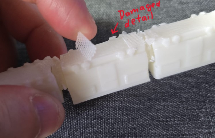
• In some way, I was lucky that my ball-and-socket joint did not fuse together on my first try. However, I may not be so lucky next time so perhaps using a parametric CAD software like Fusion 360 would be a much better choice (since you can update all the dimensions quickly). I found a reference for making ball-and-socket joints in Fusion 360 here.
3D scan an object (and optionally print it)
For this part of the assignment, I scanned an object using the Revopoint Pop 2 3D Scanner. The process is as follows:
1. Install the 3D Scanner software – In this case, it is Revo Point 5. There is a short video here that covers all the basic operations .
2. Open the 3D Scanner software - Open Revo Point 5.
3. Connect the 3D Scanner to your PC - Connect the Revopoint Pop 2 3D Scanner to your PC via USB.
4. The set-up looks like this:
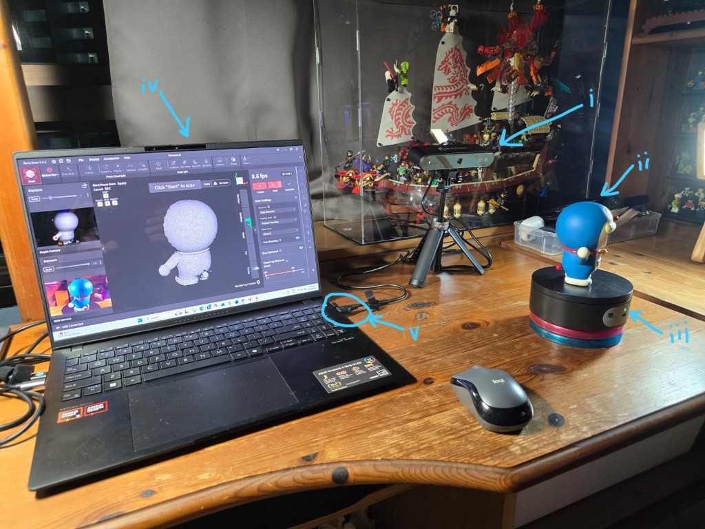
i) 3D Scanner
ii) The object to scan
iii) The turntable – revolves using battery power.
iv) PC with Revo Point 5 software
v) The 3D Scanner is connected to the PC via USB
5. Prepare to scan – This step involves aligning the object to the 3D scanner and ensuring that the camera can “see” your object. Optimally, you should position your scan subject so that the histogram bars in the “Good” or “Excellent” range. You can also control some settings such as the exposure values (you can use the auto setting if you are not sure). When the alignment is done, press start to begin the scan.
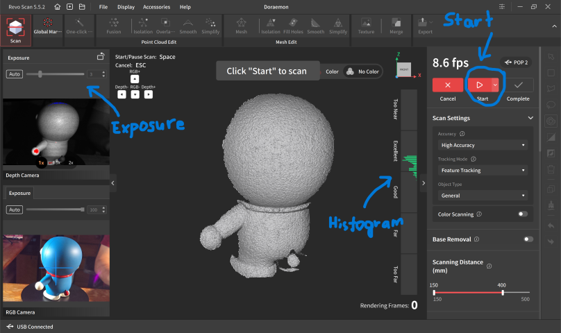
6. Scanning – The 3D scanner starts scanning the object that is revolving on the turntable. I give it at least 2 full revolutions before stopping the scan.
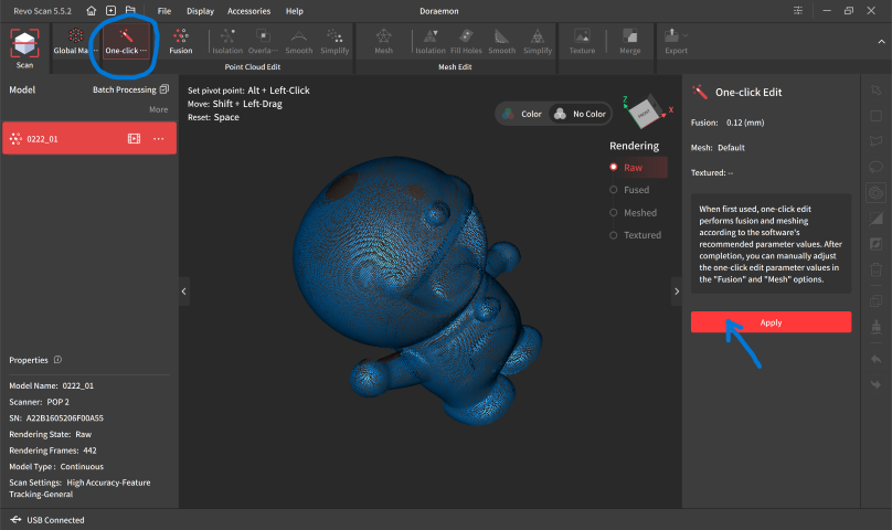
7. One-click Edit – At this point, the scan looks like many floating dots (point cloud). I select “One-click Edit” and then click “Apply”. The dots form into a mesh.
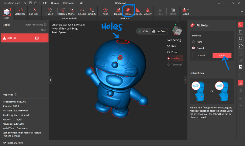
8. Fill Holes – The mesh has some holes in it. Hence, I use the “Fill Holes” function to detect and patch the holes…
9. Export to STL – The model looks okay now. I export the mesh model as an STL so that I can print it out.
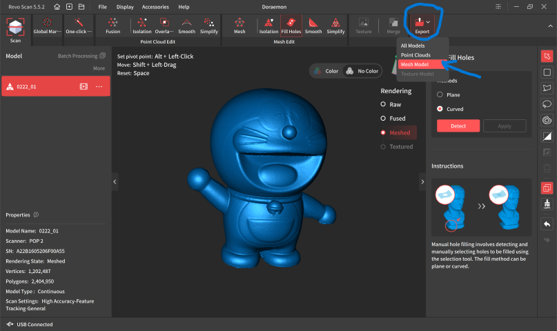
10. Simplifying the STL – I bring the freshly minted STL into Bambu Studio and immediately some warnings pop out. Apparently the STL is too complex and needs to be simplified. There are also some errors in the mesh. Thankfully, Bambu Studio can fix these issues automatically, and I now have an STL that is ready to print.
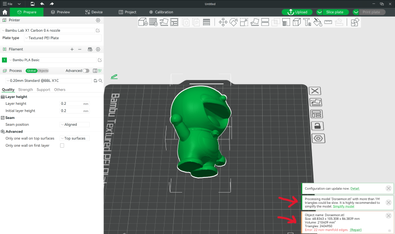
11. 3D print the STL – I use the Bambu X1-Carbon 3D printer to print out the model.
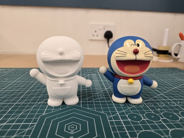
I did it! The 3D print looks close to the original subject. There are some minor defects, usually in the shadow areas and protruding features, but overall I think it looks good.
Design FilES
Link to Tinkercad ball and socket joint design files
Ball and socket test joint (.STL)
Ball and socket normal joint links (.STL)
Ball and socket Dumbbell joint links (.STL)
Link to Tinkercad train design files
