Final Project Documentation
Reginald Itiseng - Fab Academy 2025
Project Presentation Video
A 1-minute introduction to the Electric Scooter project.
Reginald Itiseng - Fab Academy 2025
A 1-minute introduction to the Electric Scooter project.
This section introduces my final project idea and begins the documentation process.
I will update this page as I make progress throughout the Fab Academy course. Below is a brief description of my proposed final project.
The Electric Scooter project aims to design and build a compact, efficient, and eco-friendly personal transportation device. The scooter will feature a lightweight frame, a brushless DC motor, and a rechargeable battery system to provide reliable urban mobility. Key features include electronic speed control, regenerative braking, and a digital dashboard for real-time speed and battery monitoring. The design will focus on safety, portability, and ease of use, making it suitable for short commutes and campus travel. By integrating smart electronics and robust mechanical components, this project demonstrates practical skills in digital fabrication, embedded systems, and sustainable design.
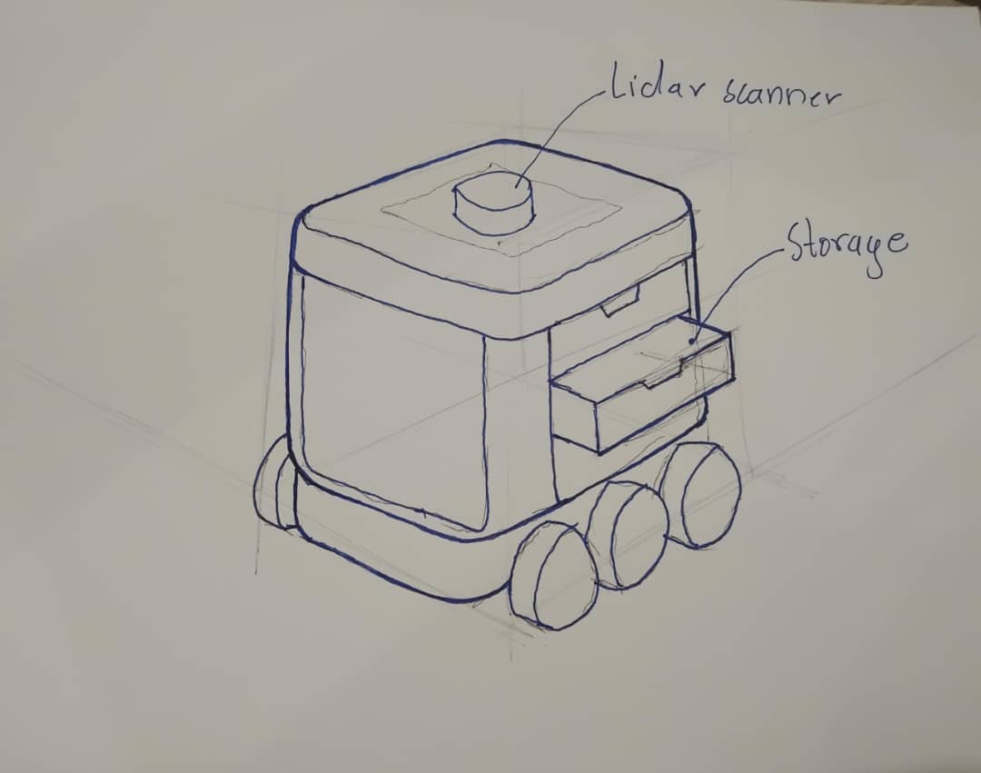
Below is a concept sketch of the Electric Scooter.
This illustration will be updated as the project develops.
Before starting my final project, I conducted extensive research to understand existing solutions, technologies, and design principles related to electric scooters. This background research helped me identify gaps in the market and opportunities for innovation.
Click on the images to view the sources.
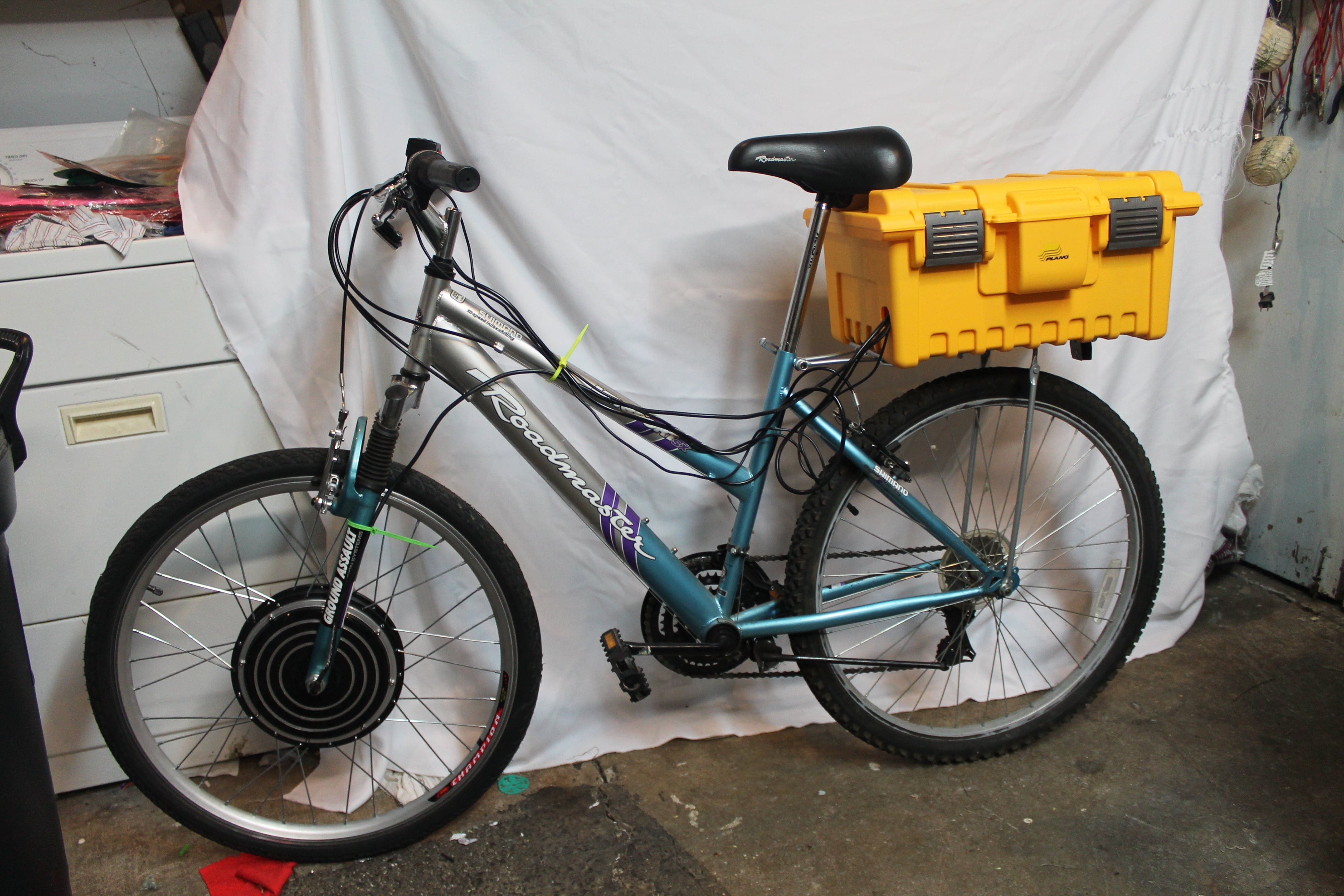
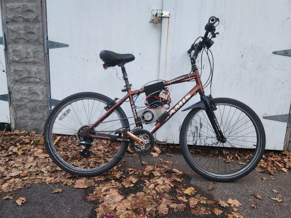

Jay Dhariwal's Final Project (2019): Jay was motivated by the urgent need for electric vehicles in India, aiming to reduce carbon emissions and dependence on imported oil. His project focused on documenting the design and fabrication of a low-cost, easy-to-build electric vehicle by converting a standard bicycle into an electric bike, with plans to add solar power and a sun-shade for thermal comfort. Jay's approach included using a modular design, starting with an e-bike conversion kit and solar system, and then developing custom components such as a motor controller PCB and smartphone integration for sensor data. He highlighted the use of spiral development, the importance of hands-on learning in electronics and fabrication, and the potential for extending the project to more advanced electric vehicles or adding features like air quality sensing and autonomous driving.
Ivan Gonzalez's Electric Scooter (2020): Ivan reclaimed and rebuilt a broken commercial electric scooter, emphasizing repair and sustainability. He detailed the process of diagnosing faults, replacing damaged electronics, and designing custom PCBs for improved control. Ivan's documentation shows the importance of reverse engineering, iterative prototyping, and using open-source tools for both hardware and software.
Maxwell Yun's Derp-e-bike (2022): Maxwell's project used 10S lithium-polymer batteries from two Turnigy packs connected in series. He selected an off-the-shelf Flipsky VESC 6 as the motor controller and a T-Motor P80 II KV100 outrunner motor, originally designed for agricultural quadcopters. This motor provides high torque at low RPM, but requires a reduction drive to power the rear wheel. Maxwell's documentation highlights practical choices in battery, controller, and motor selection, and the importance of adapting components for new applications.
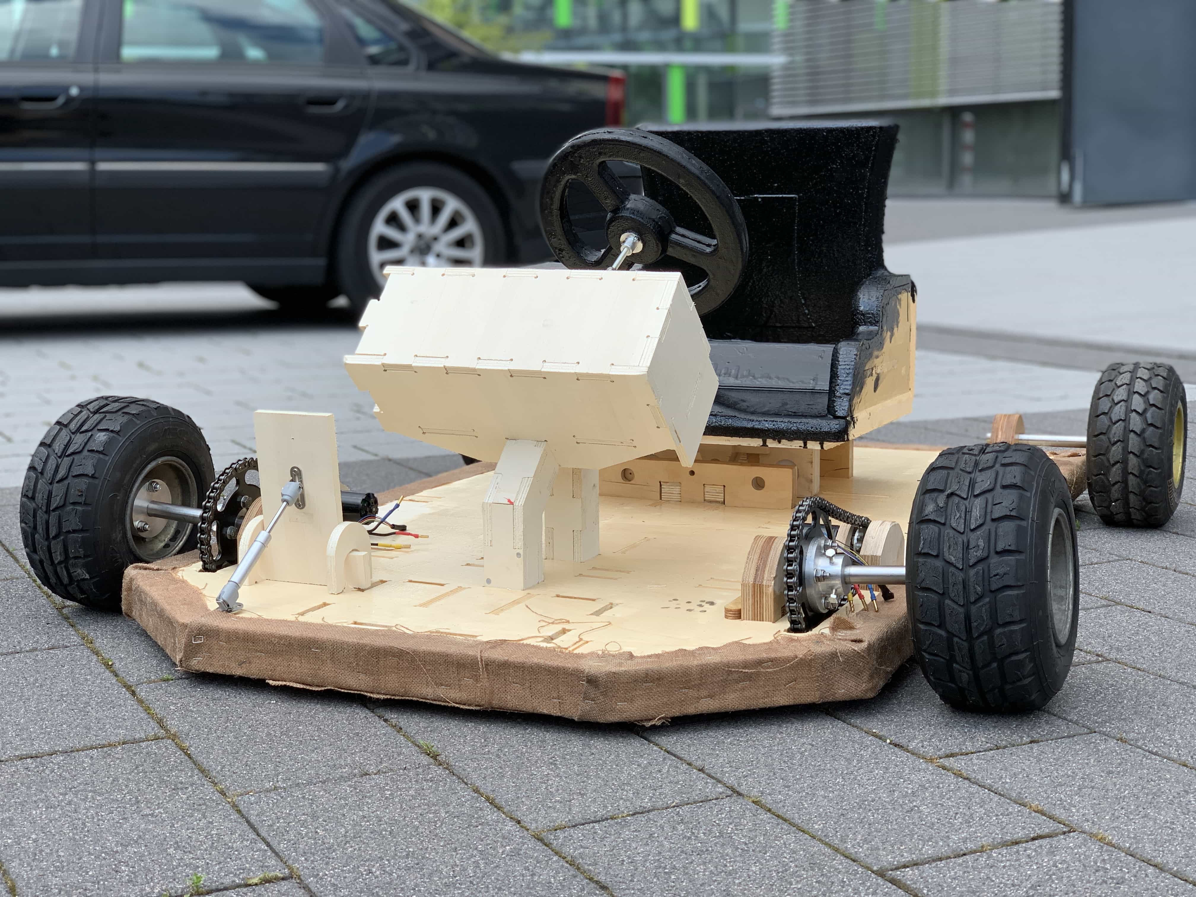
Hakan Zayin's Electric Go Cart (2019): Hakan's project began with several ideas, including an electric longboard and an arcade machine, but he ultimately chose to build a fully electric go-kart with unique features. Instead of traditional mechanical steering, he implemented an electronic tank-like steering system using a potentiometer, where turning the wheel adjusts the speed of each motor for directional control. The frame was designed in Fusion 360 and made from lightweight plywood, reinforced with jute and epoxy after testing alternatives to carbon fiber for strength and cost-effectiveness. Hakan used CNC milling for fabrication and designed custom pedals with a flex sensor for throttle control, protected in a 3D-printed flexible PLA case. He also integrated an RFID-based authentication system and a display for user feedback, connecting multiple boards via I2C. This project demonstrates the value of iterative prototyping, combining digital fabrication, embedded electronics, and creative problem-solving to achieve a robust, innovative electric vehicle.
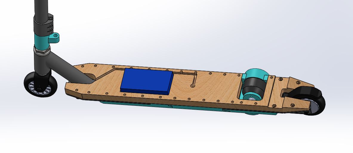
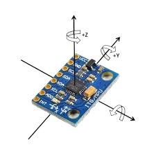
TARIGOPPULA SAI ADITYA VYNATHEYA's Self-Balancing Electric Skateboard (2018): This project aimed to create a self-balancing skateboard, I assumed as I read that it will be using using the MPU6050 gyroscope and accelerometer sensor, along with PID control for balancing and maybe a flywheel or some clever motor controll. Although the project appears to have never been fully completed, the design and approach—especially the use of real-time sensor data and control algorithms for stability—were particularly interesting to me and inspired my own ideas for implementing balance and control in personal electric vehicles.
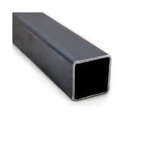
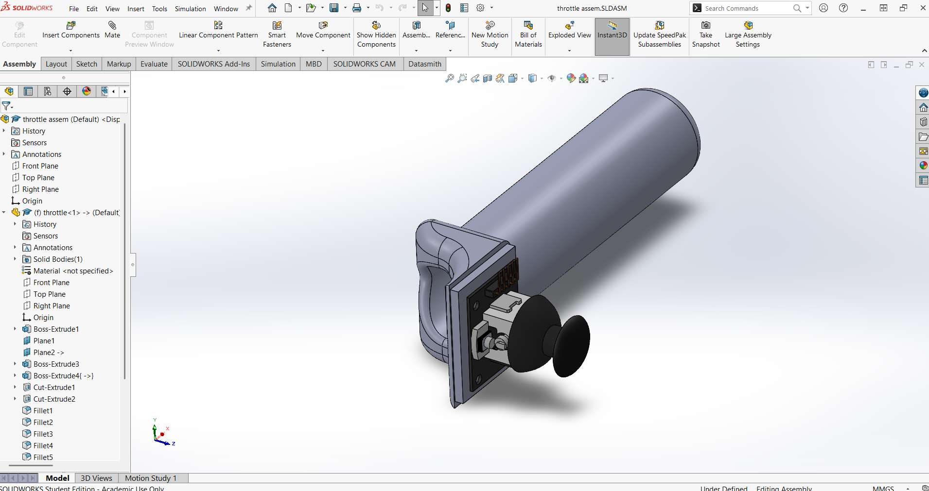
The Electric Scooter was designed to be strong, portable, and easy to fabricate using digital tools available in a Fab Lab. The main frame is constructed from mild steel square tubing for durability and rigidity, while the overall concept focuses on urban mobility, sustainability, and modularity for easy repair and upgrades.


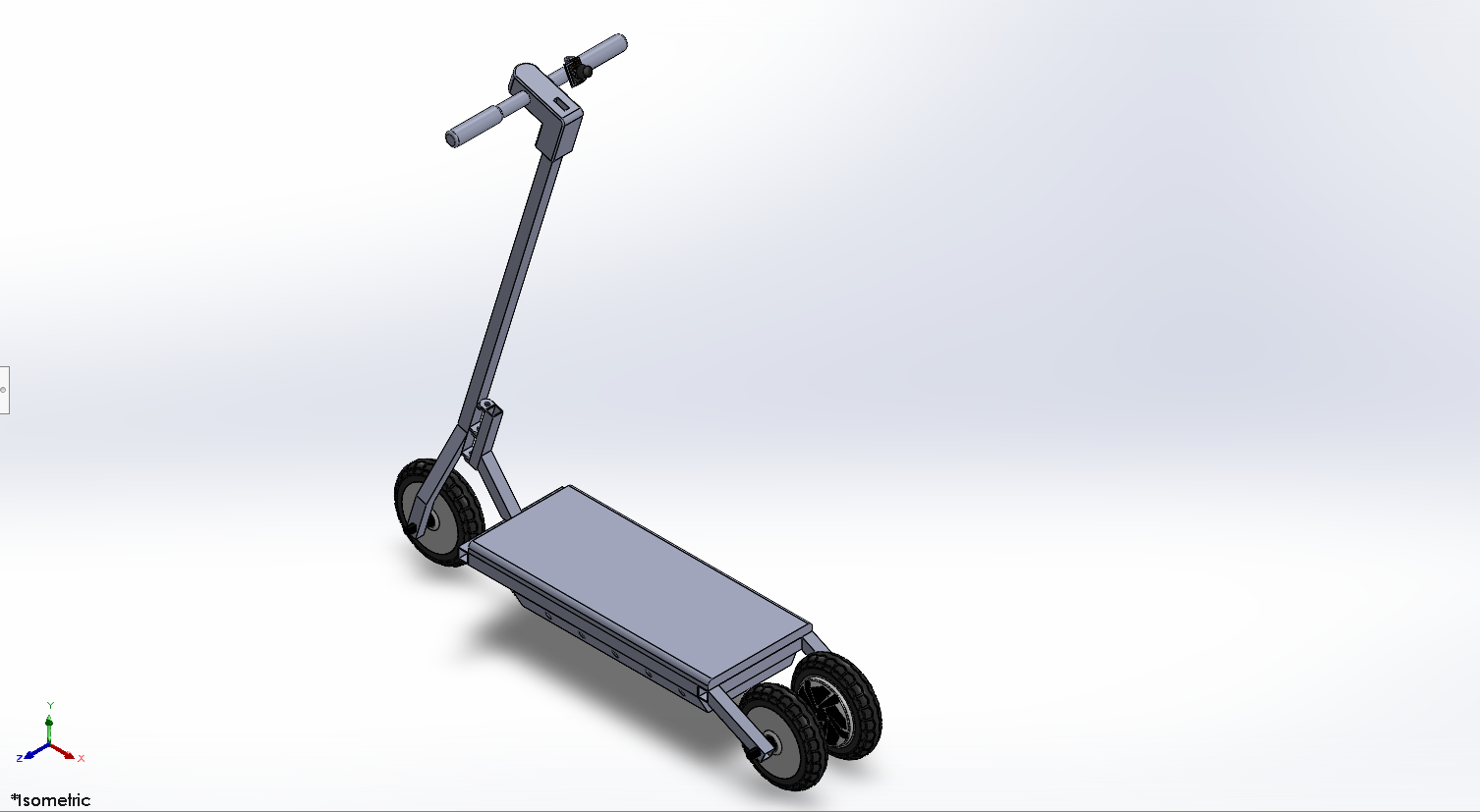
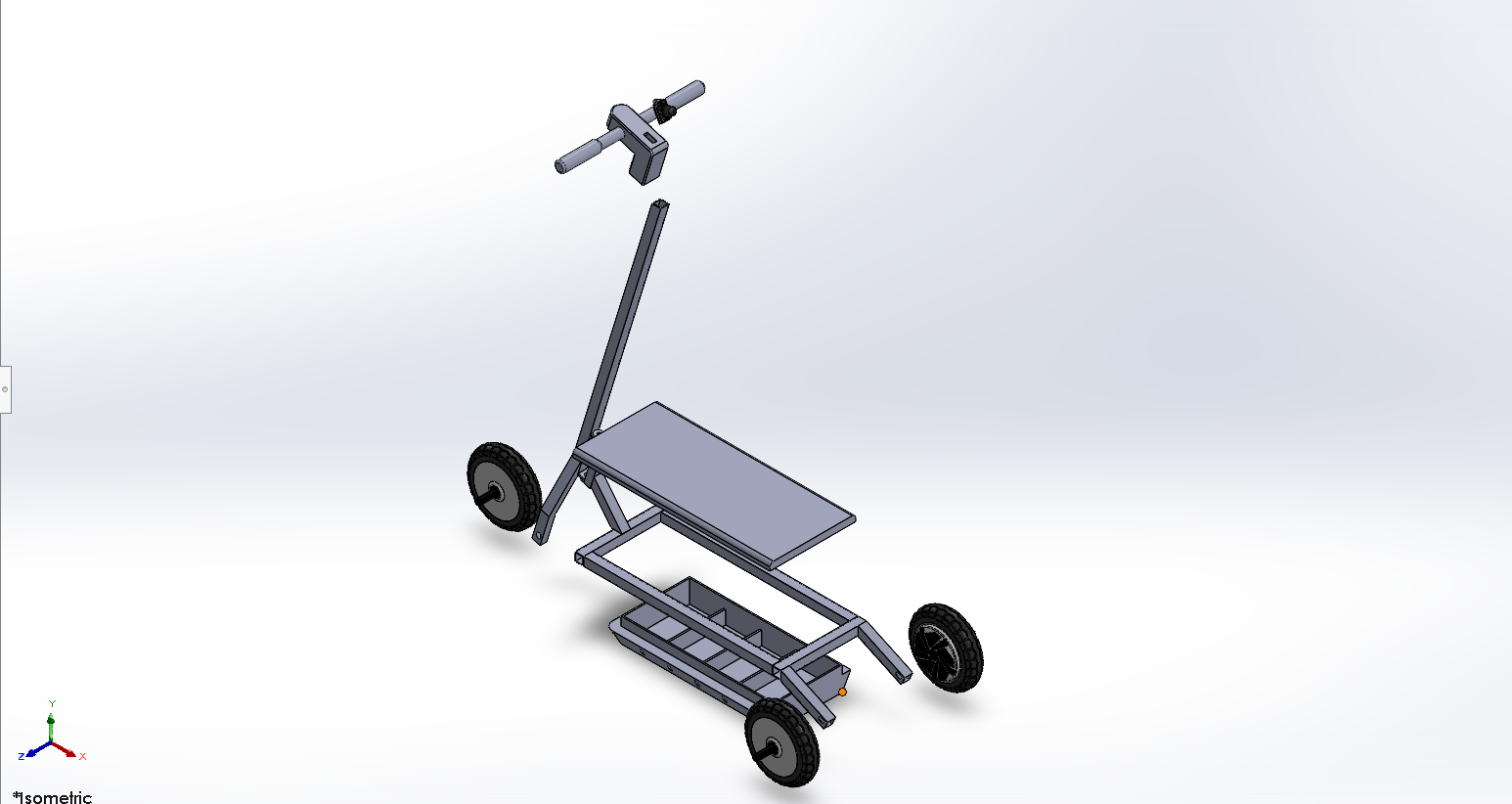
The CAD models were created in SolidWorks, allowing for precise dimensioning and easy iteration. The design files are available in the appendix for download.
Credit: The 8-inch wheel hub motor model was based on the design by John Frank, sourced from GrabCAD: hoverboard-wheel-8-bldc-motor-1. The wheels, controller, and batteries are the only parts I purchased; all other components were custom designed and fabricated.
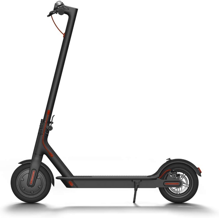
Popular commercial electric scooter known for its minimalist design and portability.
Reference for dashboard integration and safety features.
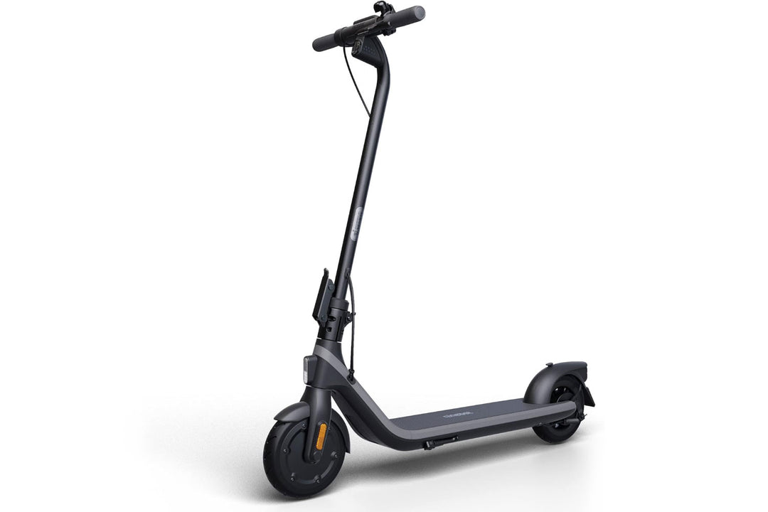
Various open-source and maker projects for custom scooter fabrication.
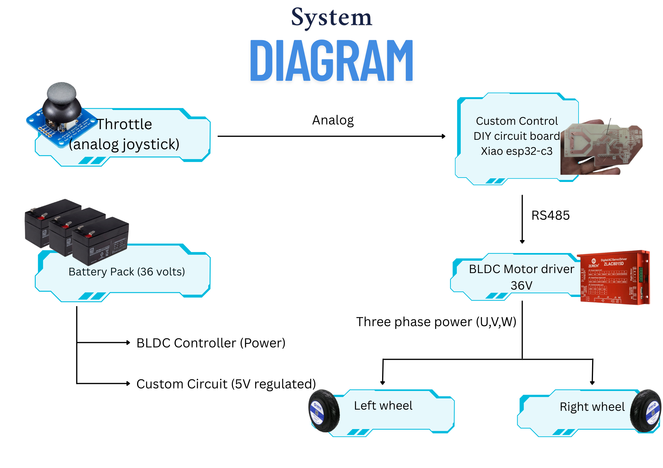
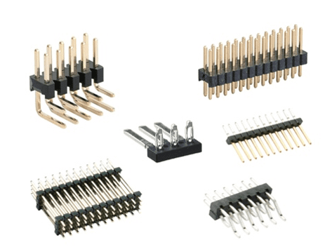
The electric scooter project required a combination of electronic and structural materials, each chosen for their specific roles in the system. Below is an explanation of the main components and materials used, and their functions in the project.

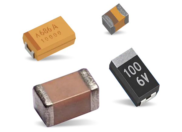
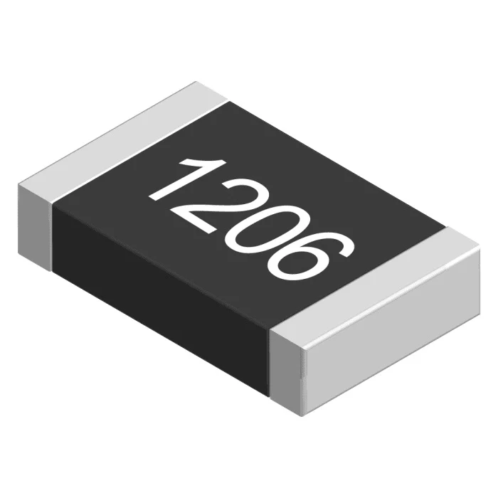
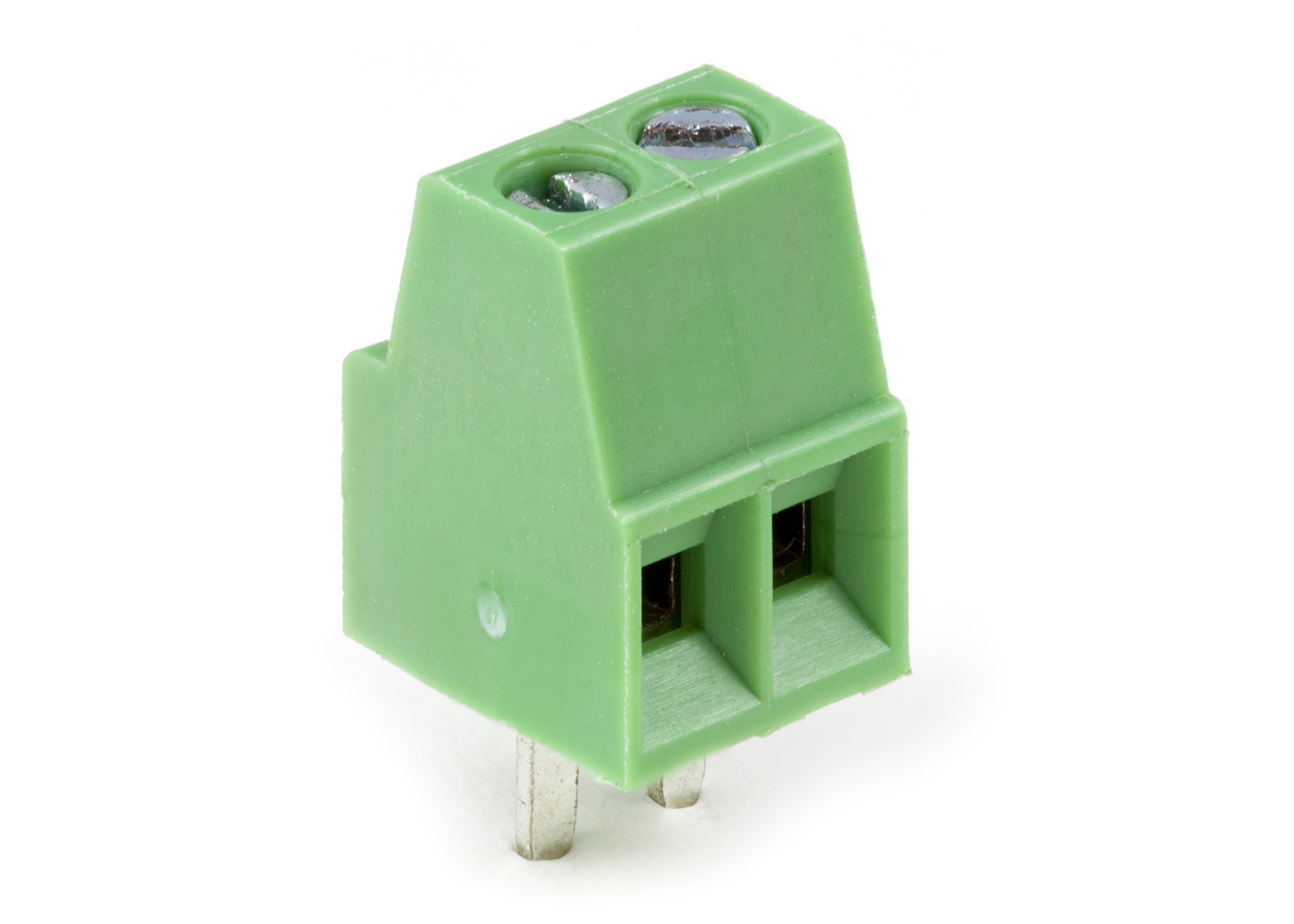
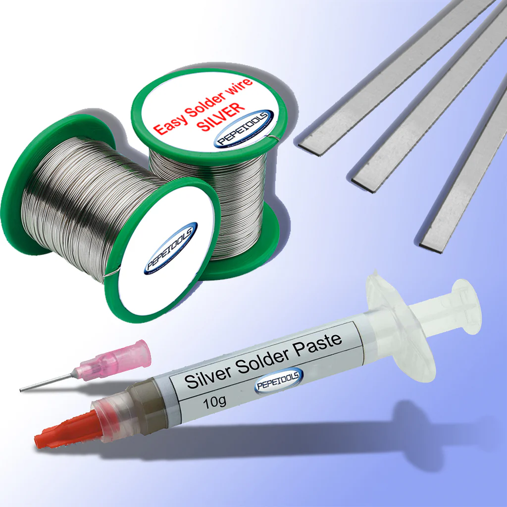
Each of these materials and components plays a crucial role in the overall function and reliability of the electric scooter. The electronics ensure precise control and monitoring, while the structural materials provide a safe and durable platform for urban mobility.
| Qty | Description | Unit Price | Link |
|---|
The fabrication of my electric scooter involved making several custom parts and systems using a combination of digital fabrication, electronics assembly, and traditional workshop techniques. Below I detail the main components I fabricated: the custom circuit board, the scooter frame, and various 3D printed enclosures and holders.
To control the BLDC motor driver and interface it with my microcontroller, I designed and fabricated a custom PCB. The board includes logic-level shifting, signal conditioning, and connectors for throttle input, brake sensors, and dashboard communication.
Design: The schematic and PCB layout were created in KiCad. I included headers for easy connection to the motor driver, microcontroller, and sensors.
RS485 Transciever:
RS485 is a differential serial communication standard widely used for robust, long-distance, and noise-resistant data transmission in industrial and embedded systems. In my circuit, the MAX485 chip implements the RS485 protocol, acting as a bridge between the microcontroller (UART) and the motor driver, allowing reliable data exchange even in electrically noisy environments.
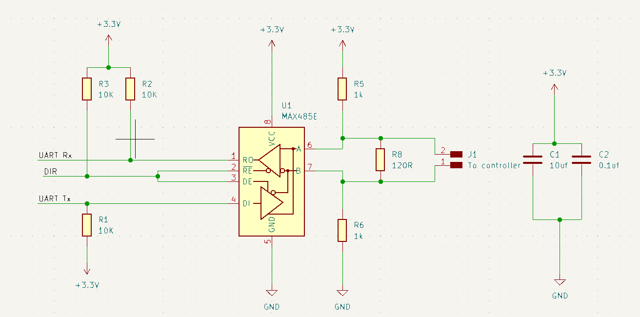
The section of the circuit showing how the RS485 tranciever is implemented.
This setup enables the microcontroller to send and receive UART data over the RS485 bus, providing noise immunity and supporting longer cable runs between the control board and the motor driver.
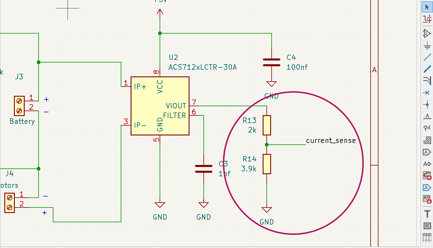
Current and Voltage Sensing:
The circuit includes a current sensing IC ACS712 and voltage divider (R9, R10) to monitor the battery current and voltage. This data is fed back to the microcontroller for real-time monitoring and control.
To protect the analog input of the microcontroller from voltage spikes or accidental overvoltage from the voltage sensing circuit, a BZX85 3.0V Zener diode and a 1kΩ resistor (R11) are used. The resistor R11 limits the current into the analog pin, while the Zener diode clamps the voltage to a safe maximum (about 3V), preventing the analog pin from being exposed to voltages higher than the microcontroller can tolerate.
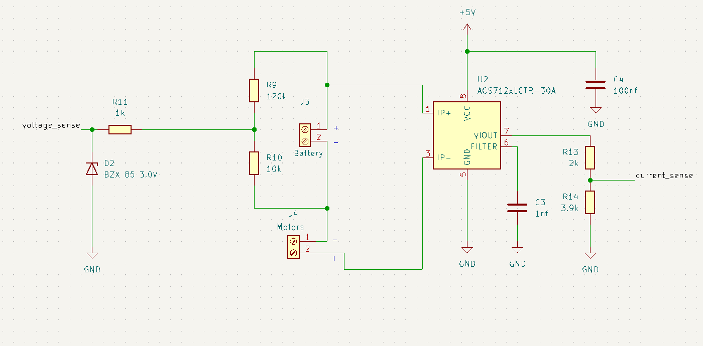
The section of the circuit showing how the current and voltage sensing is implemented.
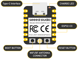
Connections to the microcontroller (Xiao esp32 c3):
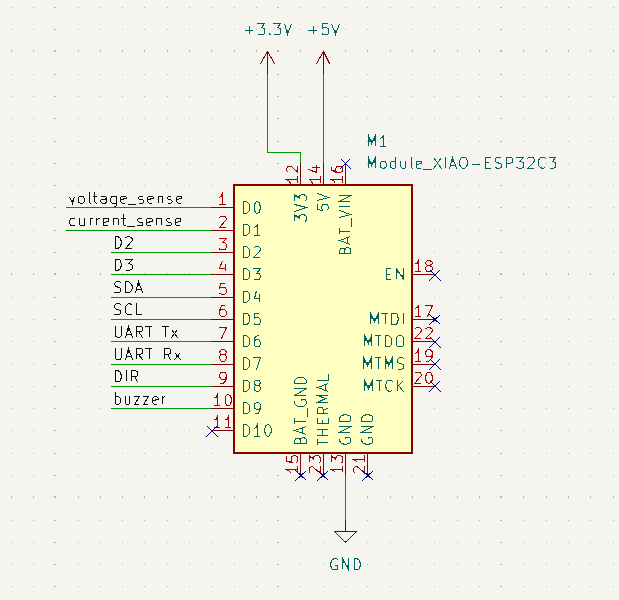
The section of the circuit showing how the current and voltage sensing is implemented.
The complete circuit design
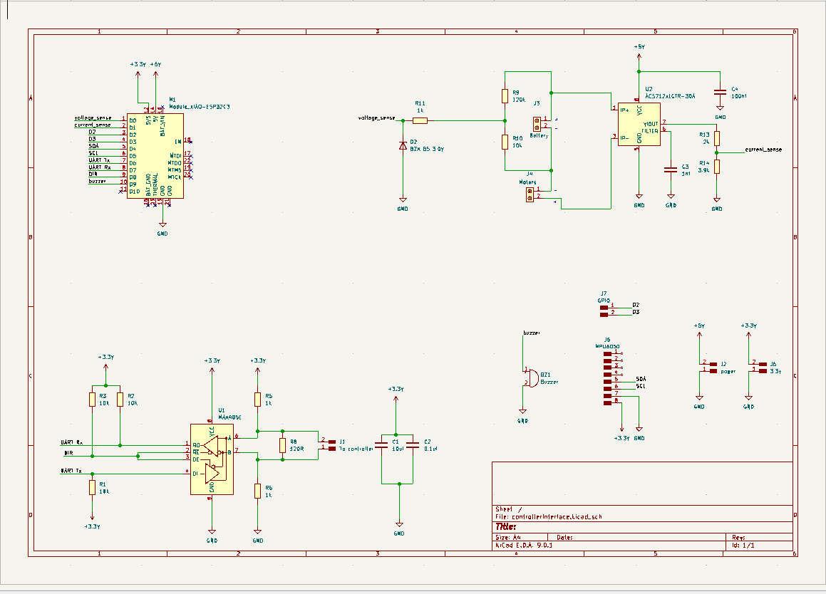
The section of the circuit showing how the current and voltage sensing is implemented.
PCB Layout: The PCB layout was designed in KiCad, ensuring proper trace widths for current handling and clearances for high-voltage components.
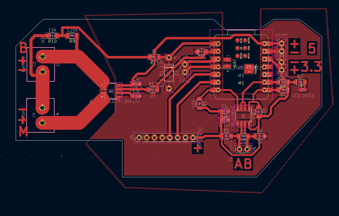
PCB layout showing component placement and routing.
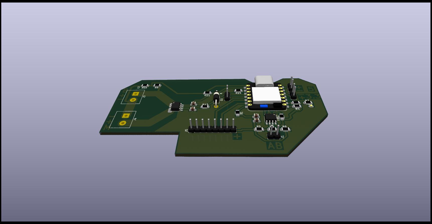
PCB layout shown on cad model.
Fabrication: The PCB was milled using the Fab Lab's desktop PCB milling machine. After milling, I soldered all components by hand, including pin headers, resistors, capacitors, and connectors.
PCB Fabrication Process (Bungard CCD)
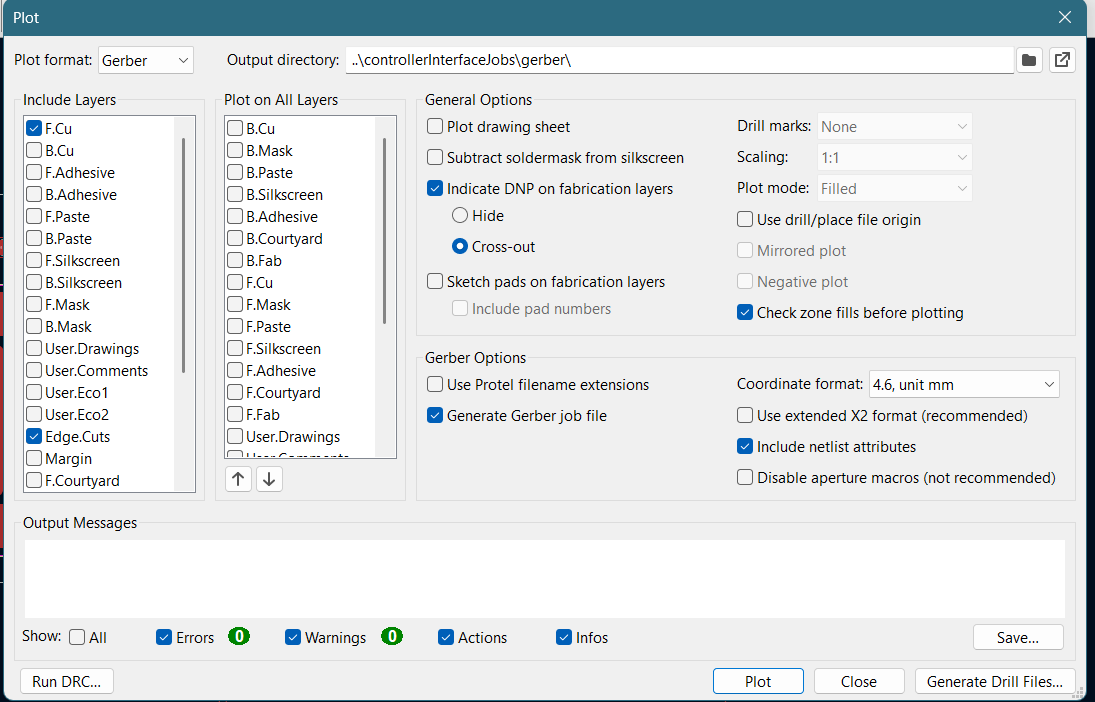
Exporting Gerber and drill files in KiCad.
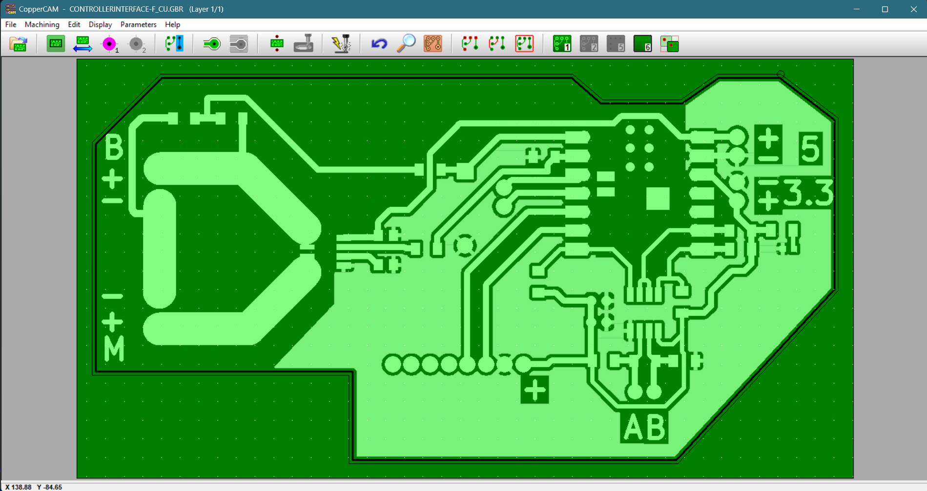
Gerber and drill files loaded in CopperCAM.
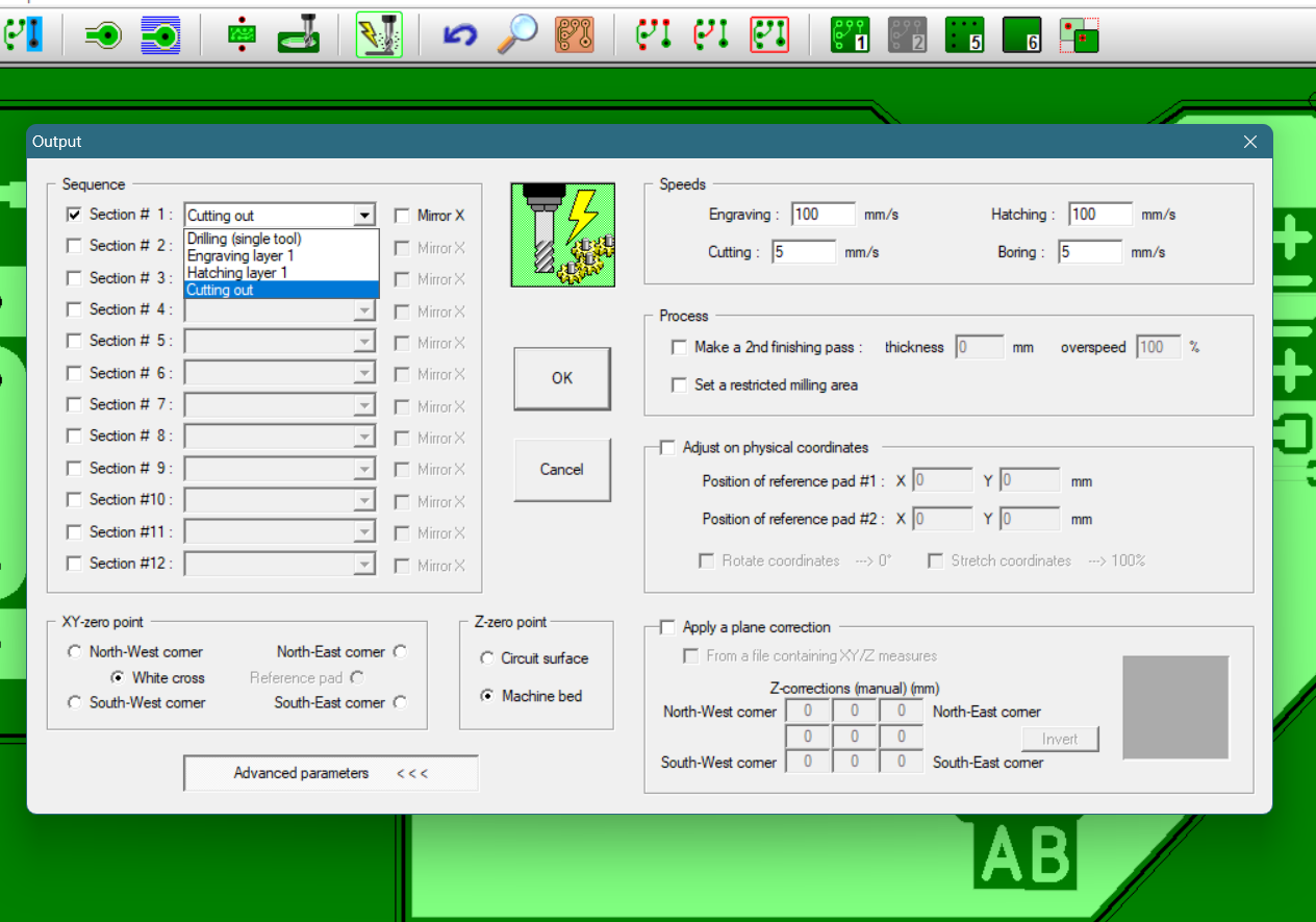
After importing, I made sure the tool selection for each operation was correct. For both engraving and hatching, I used a 30-degree V-bit with a tip diameter of 0.1 mm. For cutting and drilling, a 1 mm diameter flute cutter was used. Larger diameter holes would be made through a boring operation at a speed of 5 mm/s.
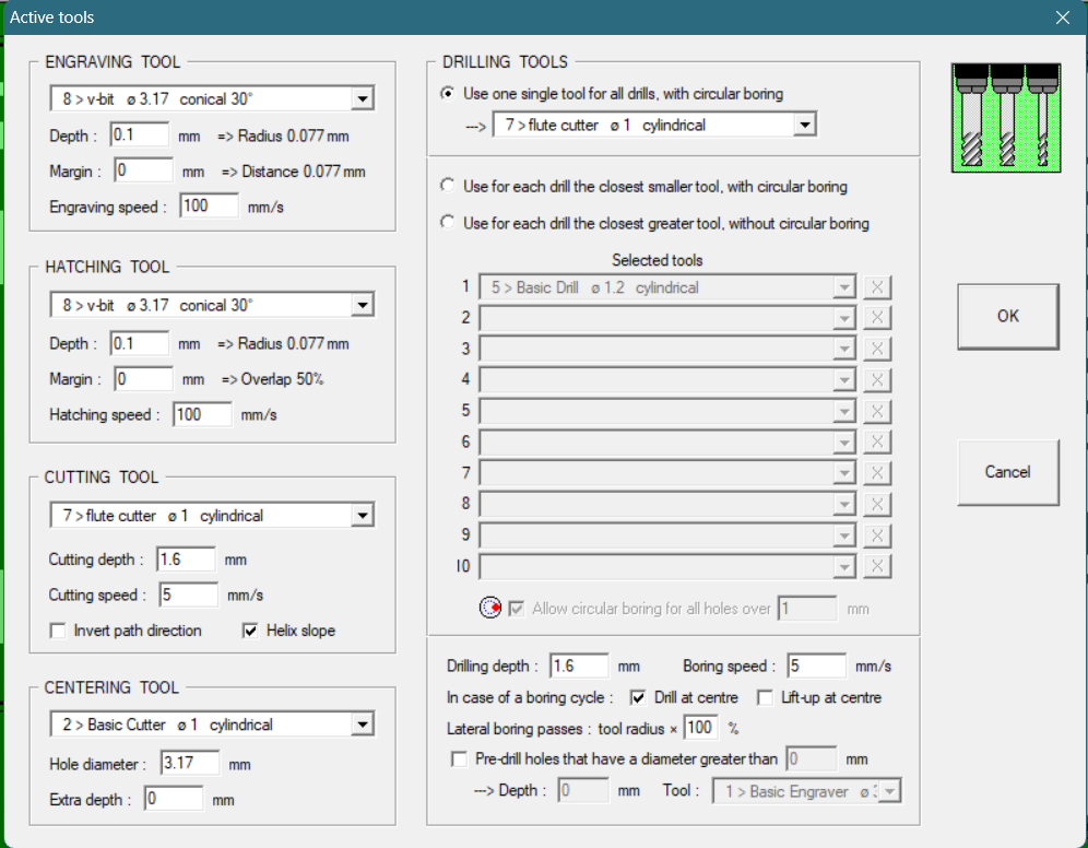
Tool selection and operation settings in CopperCAM.
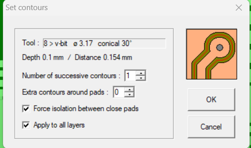
CopperCAM settings used for calculating board contours before generating toolpaths.
I also generated hatches to remove all unnecessary copper from the PCB. This is important because leaving large areas of unused copper can lead to unwanted electrical connections (shorts), increased risk of corrosion, and can interfere with high-frequency signals due to stray capacitance. Hatching is a process where the software fills unused copper areas with a pattern of parallel lines (hatch lines) instead of leaving them as solid copper. These hatch areas help maintain mechanical stability of the board, reduce copper waste, and minimize the risk of warping during soldering by balancing copper distribution.
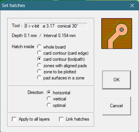
Settings used for generating hatches.
Preview of Final Circuit:
After completing all the necessary calculations and adjustments in the PCB design software, the final circuit preview provides a realistic visualization of how the board will look once fabricated. This includes the placement of all components, traces, drills, and labels, ensuring that the design is ready for manufacturing and assembly.
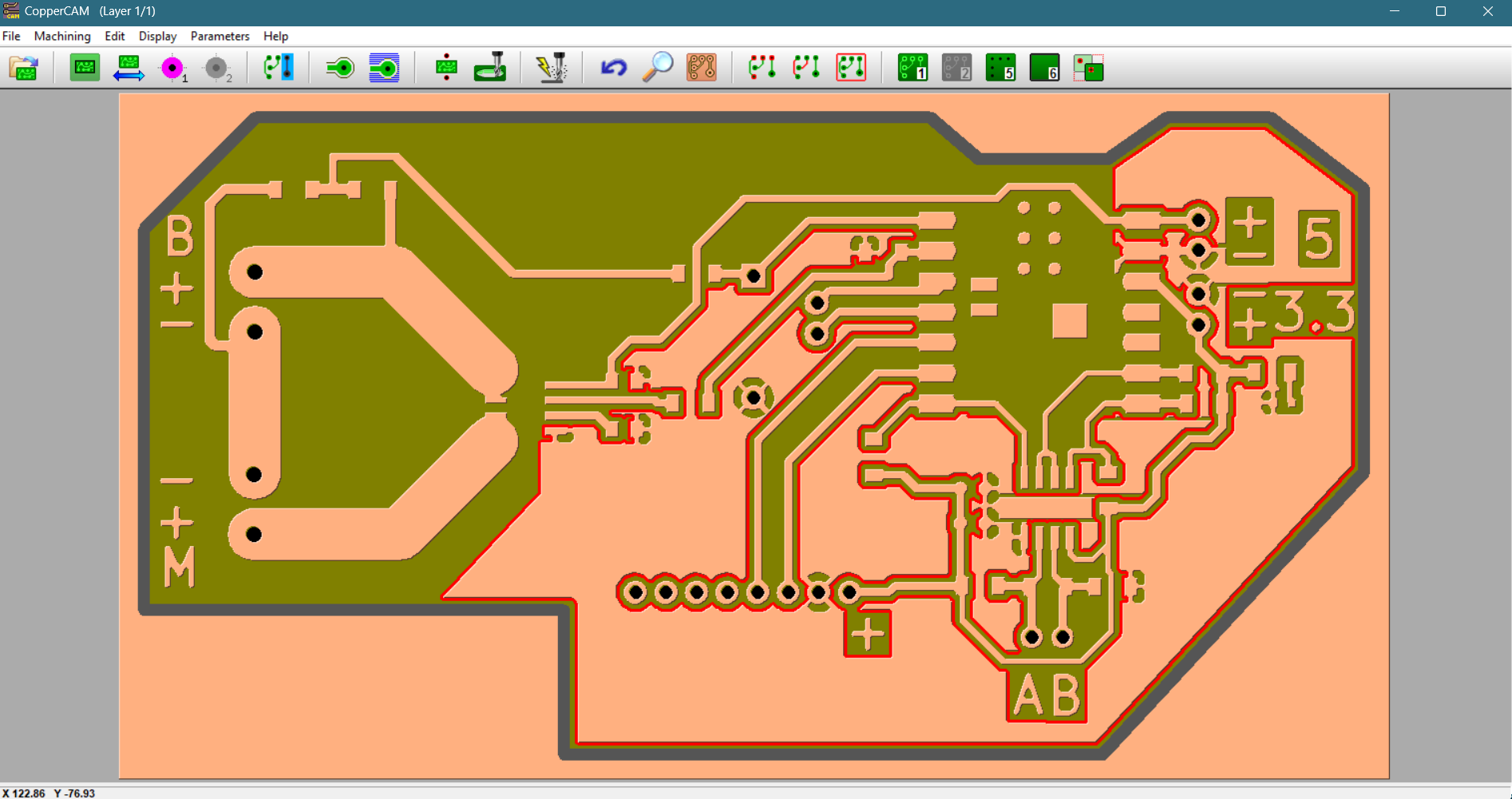
Preview of the completed circuit as rendered in CopperCAM before fabrication.
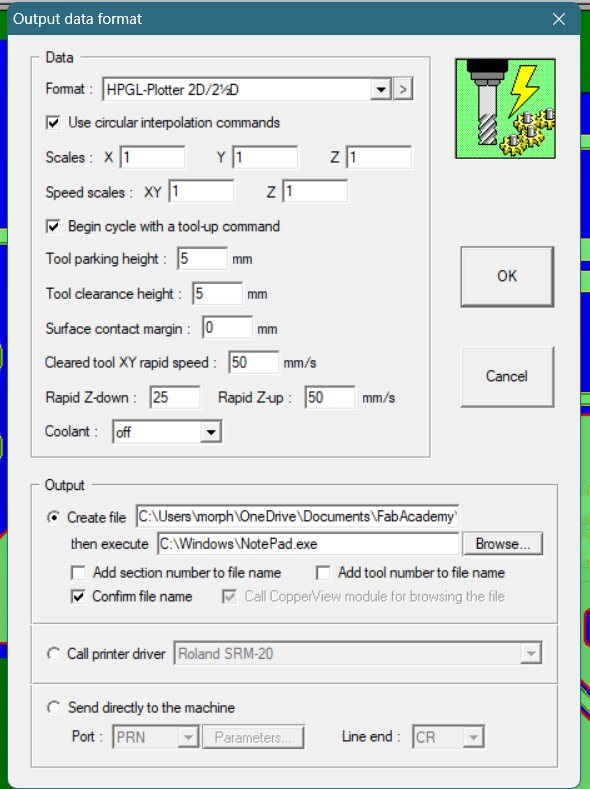
Setting the outptut data format and settings
To have more control over the PCB fabrication process, I generated separate HPGL files for each operation: cutout, hatches, drills, and traces. This approach allowed me to fine-tune the milling parameters for each step, such as adjusting spindle speed, depth, and tool selection according to the specific requirements of each process. By isolating these operations, I could also pause between steps to inspect the board, change tools, or make adjustments, ensuring higher precision and reducing the risk of errors during manufacturing.
This is where each layer toolpath was exported to separate files, the engarving layer for traces, hatches layer for removing unwanted copper, drills and cutout.
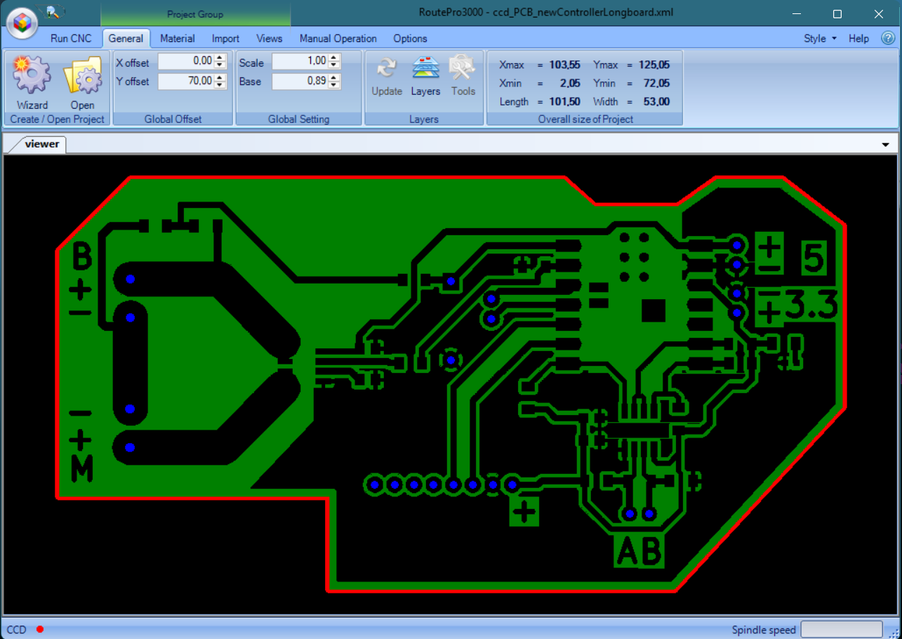
HPGL files loaded and ready for milling in RoutePro 3000.
Video: Bungard CCD milling the PCB.

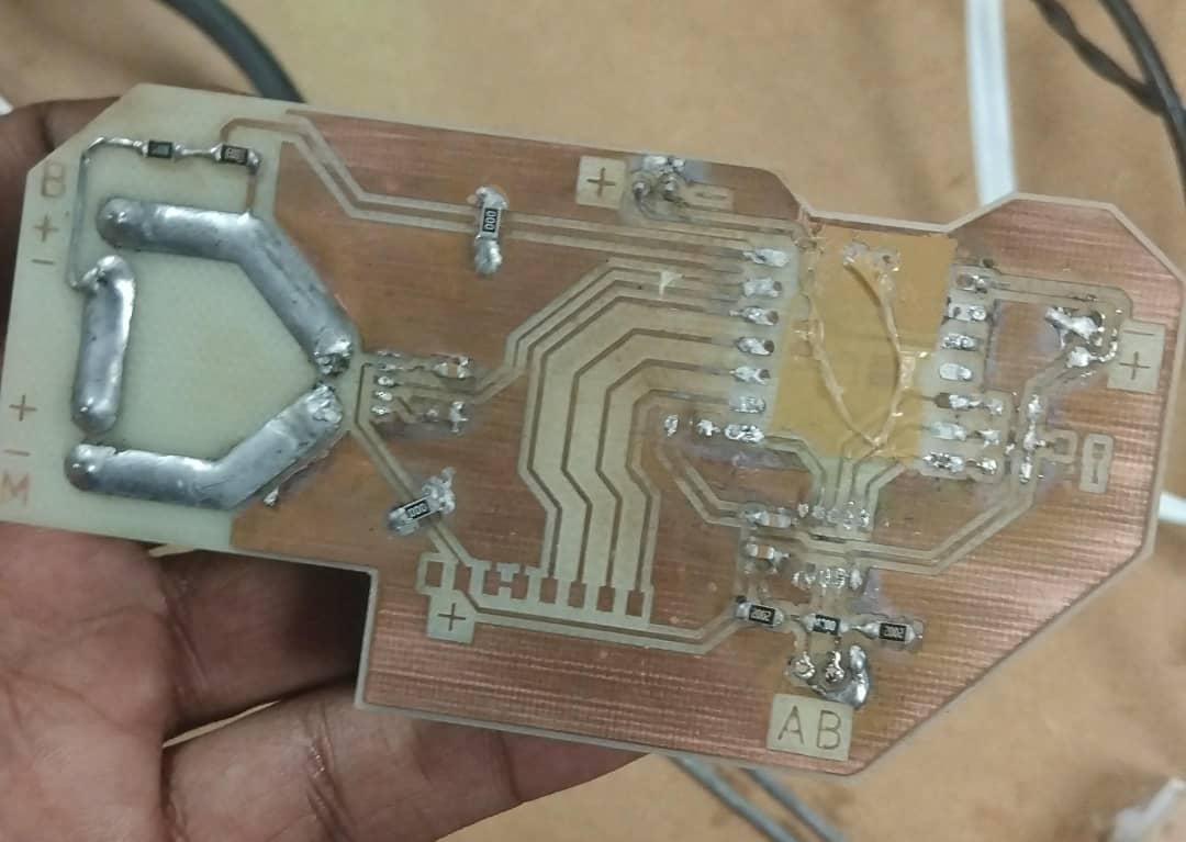
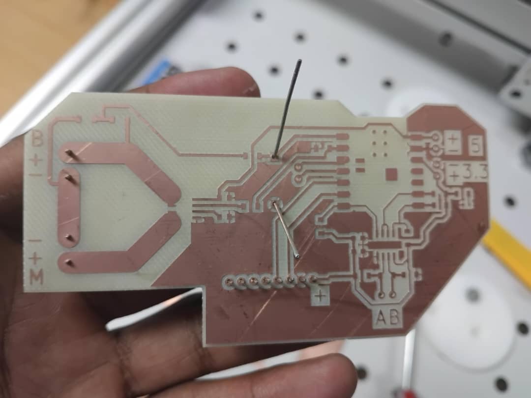
PCB after milling and drilling, ready for soldering.
Video: Soldering components onto the fabricated PCB.
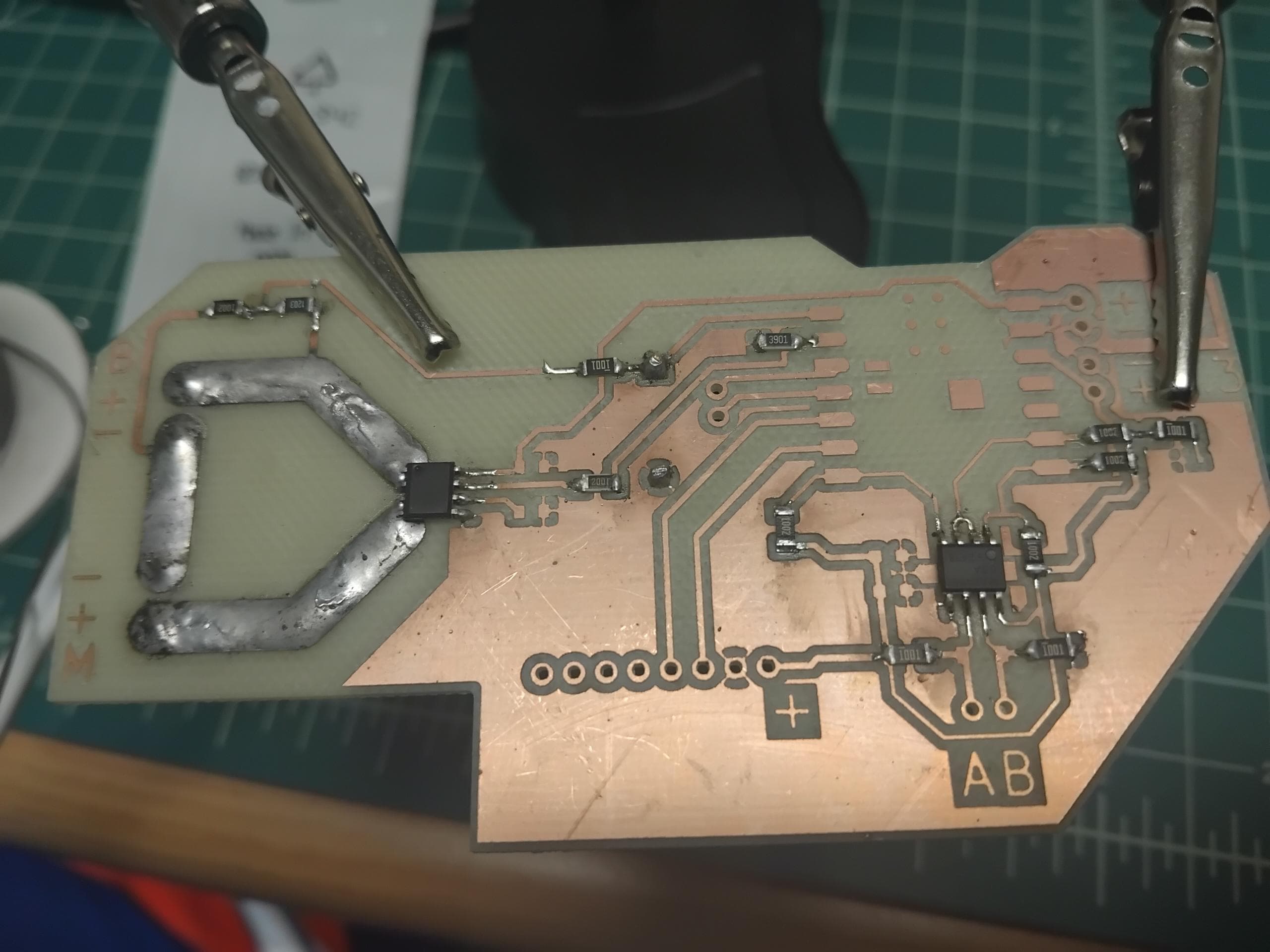
Assembled and soldered PCB.
Video: Testing the assembled PCB in operation with the motor driver.
To test the motor driver and verify reliable communication, I wrote Arduino code that fully implements the Modbus RTU protocol over RS485. This allowed the microcontroller to send commands and receive status data from the motor driver, ensuring that the custom PCB and RS485 transceiver worked as intended.
Below is a simplified example of the Arduino code used for Modbus communication with the motor driver:
/*
  * This code will be the back bone of my electric scooter project.
  * It will be used to control the motor driver using Modbus RTU over RS485.
  * This code demonstrates how to communicate with a motor driver using Modbus RTU over RS485.
  * It uses the ModbusMaster library to handle Modbus RTU framing and CRC.
  * The MAX485 transceiver is used to convert UART signals to RS485 differential signals.
  * The code initializes the Modbus communication, sends commands to the motor driver.
*/

#include <ModbusMaster.h>
#include <Wire.h>

// Constants for MAX485 RS485 Transceiver
// The pins bellow are the physicall pins of the Max 485 transceiver connected to the ESP32-C3 Xiao,
// they controll the direction of the data flow in the RS485 bus.
#define MAX485_DE           D9
#define MAX485_RE_NEG       D8


// Next i define the Modbus registers for the motor driver
// These registers are used to control the motor driver and read its status.
// The addresses are based on the motor driver's Modbus documentation.
// The addresses are in hexadecimal format.
// these are enough to get the motor driver working in velocity mode,
// which is the mode I will be using for my scooter.

/*
  * Keep in mind that these are the addresses I need to keep adjusting in order
  * to controll the behaviour of the motor driver and it wheels.
  */
  #define CONTROL_WORD 0x200E
  #define CONTROL_MODE 0x200D

  #define ACCELERATION_TIME_LEFT    0x2080
  #define ACCELERATION_TIME_RIGHT   0x2081
  #define DECELERATION_TIME_LEFT    0x2082
  #define DECELERATION_TIME_RIGHT   0x2083

  #define TARGET_VELOCITY_LEFT      0x2088
  #define TARGET_VELOCITY_RIGHT     0x2089
  #define ACTUAL_VELOCITY_LEFT      0x20AB
  #define ACTUAL_VELOCITY_RIGHT     0x20AC

  // Settings for the motor driver (CONTROL_WORD values)
  const uint16_t QUICK_STOP   = 0x05;
  const uint16_t CLEAR_FAULT  = 0x06;
  const uint16_t STOP         = 0x07;
  const uint16_t ENABLE       = 0x08;

  // needed in position control
  const uint16_t START        = 0x10;  // SYNC
  const uint16_t START_LEFT   = 0x11;  // ASYNC
  const uint16_t START_RIGHT  = 0x12;  // ASYNC

const uint16_t ACCELERATION_DECELERATION_TIME = 1000; // In milliseconds(ms)

// ModbusMaster object instantiation
ModbusMaster node;

/*
  * IMPORTANT FNCTION PROTOTYPES
  * The function preTransmission() is called before each Modbus transmission.
  * It sets the MAX485 transceiver to transmit mode by setting the DE and RE_NEG pins high.
  * The function postTransmission() is called after each Modbus transmission.
  * It sets the MAX485 transceiver back to receive mode by setting the DE and RE_NEG pins low.
  * This is necessary to switch the transceiver between transmit and receive modes.
  * The writeRegister() function is a helper function that writes a value to a specific Modbus register.
  * It uses the ModbusMaster library to send a write request to the motor driver.
  * The syncronousMove() function sends a command to the motor driver to set the
  * target velocities for both wheels.
  * It uses the ModbusMaster library to write multiple registers at once.
  */
  void preTransmission();
  void postTransmission();
  bool writeRegister(uint16_t address, uint16_t value);
  bool syncronousMove(int leftVelocity, int rightVelocity);


void setup() {
    pinMode(MAX485_RE_NEG, OUTPUT);
    pinMode(MAX485_DE, OUTPUT);

    // Init in receive mode
    digitalWrite(MAX485_RE_NEG, 0);
    digitalWrite(MAX485_DE, 0);

    Serial.begin(115200);
    Serial1.begin(115200, SERIAL_8N1, 20, 21);

    // Modbus slave ID 1
    node.begin(1, Serial1);


    // Callbacks allow us to configure the RS485 transceiver correctly
    node.preTransmission(preTransmission);
    node.postTransmission(postTransmission);

    // System start with default as Velocity mode
    Serial.println("connecting to servo driver...");


    /*
      * The following code is used to initialize the motor driver and set it to velocity mode.
      * It sends a series of Modbus commands to the motor driver to clear faults, enable it,
      * set the control mode to velocity, and configure acceleration and deceleration times.
      * The values used in the commands are based on the motor driver's Modbus documentation.
      * The code will keep trying to connect to the motor driver until it succeeds.
      */
      while(true){
        // start by handshaking with the motor driver
        if (writeRegister(CONTROL_WORD, CLEAR_FAULT) &&
            writeRegister(CONTROL_WORD, ENABLE) &&
            writeRegister(CONTROL_MODE, 0x03) &&
            writeRegister(ACCELERATION_TIME_LEFT, ACCELERATION_DECELERATION_TIME) &&
            writeRegister(ACCELERATION_TIME_RIGHT, ACCELERATION_DECELERATION_TIME) &&
            writeRegister(DECELERATION_TIME_LEFT, ACCELERATION_DECELERATION_TIME) &&
            writeRegister(DECELERATION_TIME_RIGHT, ACCELERATION_DECELERATION_TIME)) {

          Serial.println("Motor driver is Listening...");
          //isMotorDriverOnline = true;
          delay(500);
          break;
        }else{
          Serial.println("Reaching out to Motor driver...");
        }
        delay(1000);
      }


}

/*
  * The loop function is where the main logic of the program runs.
  * In this case, it sends a command to the motor driver to move both wheels at a speed of 350.
  * The syncronousMove() function is called to send the command.
  * The function returns true if the command was sent successfully, and false otherwise.
  * The loop will keep running, sending the same command every second.
  */
void loop() {
  bool moveSent = syncronousMove(350, 350);
  Serial.println("Speeding...");
  delay(1000);
}

// Callback function before transmission
void preTransmission() {
    digitalWrite(MAX485_RE_NEG, 1);
    digitalWrite(MAX485_DE, 1);
}

// Callback function after transmission
void postTransmission() {
    digitalWrite(MAX485_RE_NEG, 0);
    digitalWrite(MAX485_DE, 0);
}

/**
  * This function writes a value to a specific Modbus register.
  * It uses the ModbusMaster library to send a write request to the motor driver.
  * The function returns true if the write operation was successful, and false otherwise.
  */
  bool writeRegister(uint16_t address, uint16_t value) {
    return node.writeSingleRegister(address, value) == 0;
  }

/**
  * This function sends a command to the motor driver to set the target velocities for both wheels.
  * It uses the ModbusMaster library to write multiple registers at once.
  * The left velocity is written to register 0x2088 and the right velocity to register 0x2089.
  * The function returns true if the command was sent successfully, and false otherwise.
  */
  bool syncronousMove(int leftVelocity, int rightVelocity){
    node.setTransmitBuffer(0, -leftVelocity);
    node.setTransmitBuffer(1, rightVelocity);

    return node.writeMultipleRegisters(0x2088, 2);
  }
This code uses the ModbusMaster library to handle Modbus RTU framing and CRC, and toggles the MAX485 transceiver between transmit and receive modes. It demonstrates reading a register from the motor driver and printing the result, confirming that the RS485 and Modbus implementation is functional.
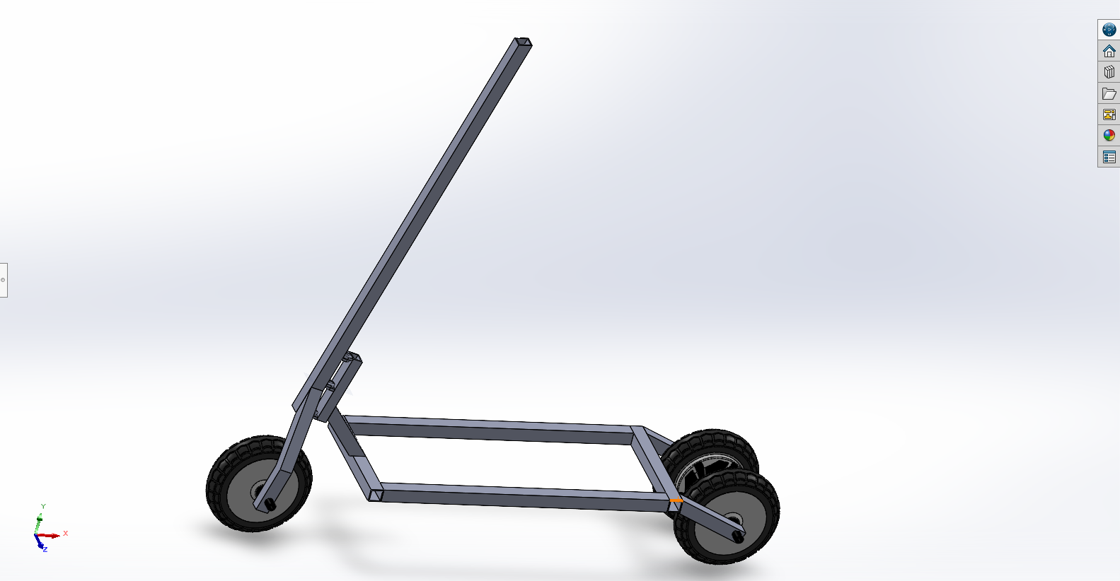
The main frame of the scooter was fabricated from mild steel square tubing for strength and durability. The design was optimized for weight and ease of assembly.
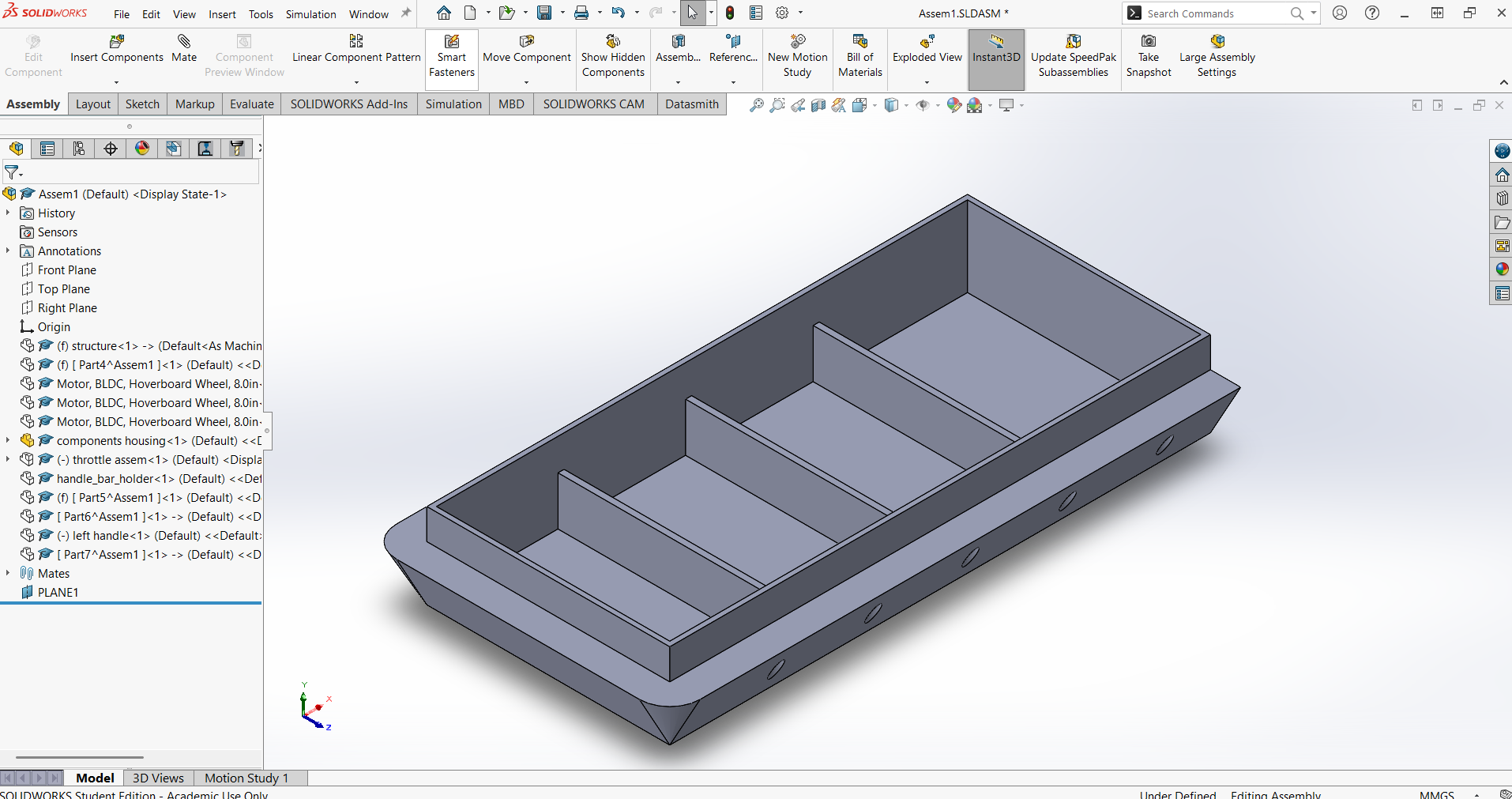
The scooter frame was modeled in SolidWorks using the Weldments feature, which is ideal for designing metal structures that will be welded together. Weldments allow you to create complex frames from standard profiles, manage cut lists automatically, and visualize joints and intersections, making it much easier to plan fabrication and assembly for welded metal projects.
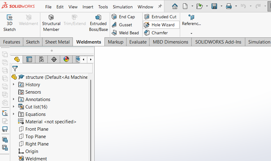
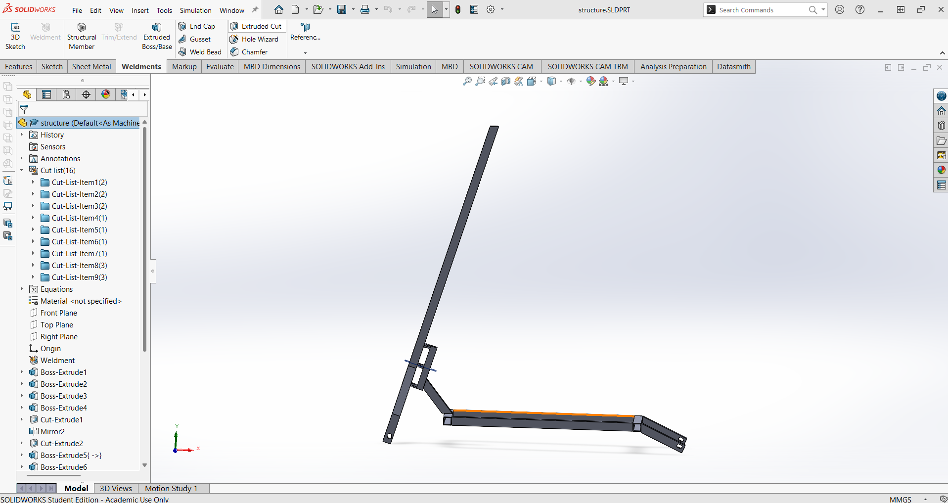
Using Weldments in SolidWorks enabled efficient design, accurate cut lists, and clear visualization of the welded joints, ensuring the frame could be fabricated precisely as modeled.
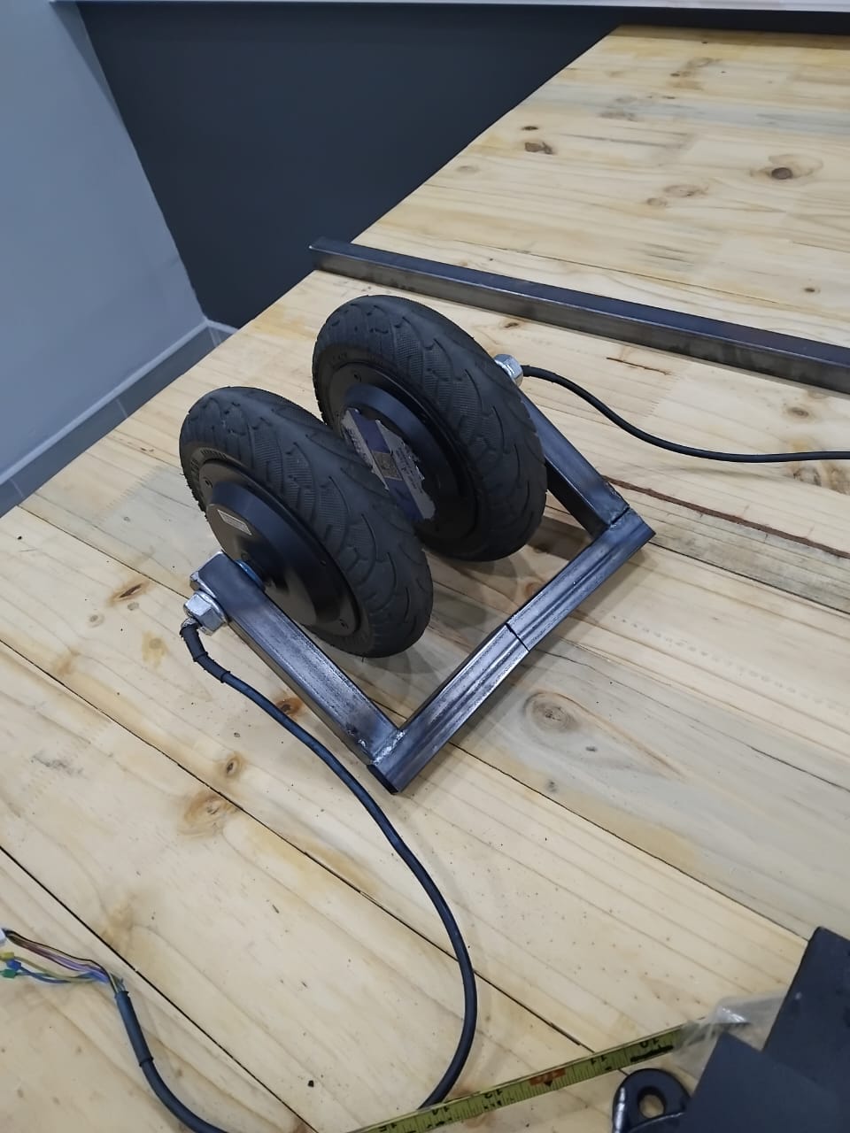
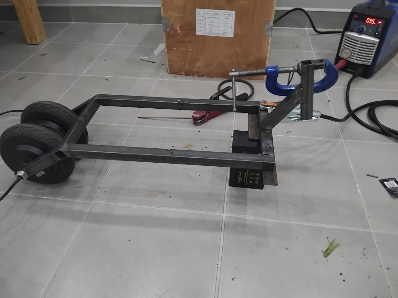
Arc welding was used to join the steel tubes, ensuring strong and durable joints for the scooter frame. Proper safety gear and ventilation were used throughout the process.
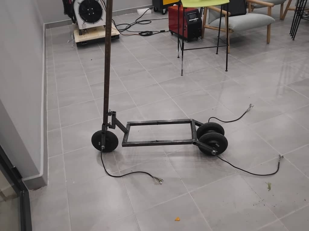
Scooter frame welded from mild steel square tube.
To protect the electronics and secure the battery and motor driver, I designed and 3D printed an enclosure to hold the components firmly.
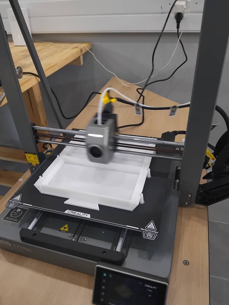
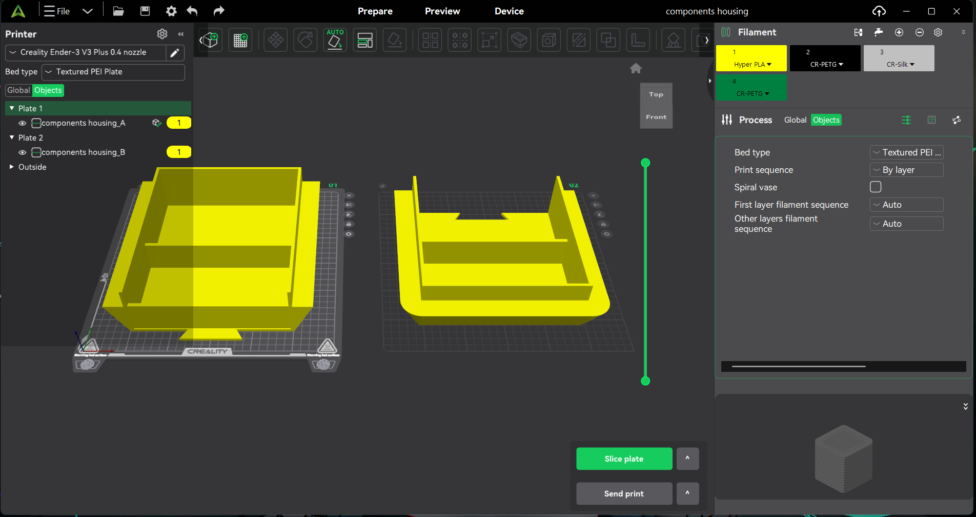
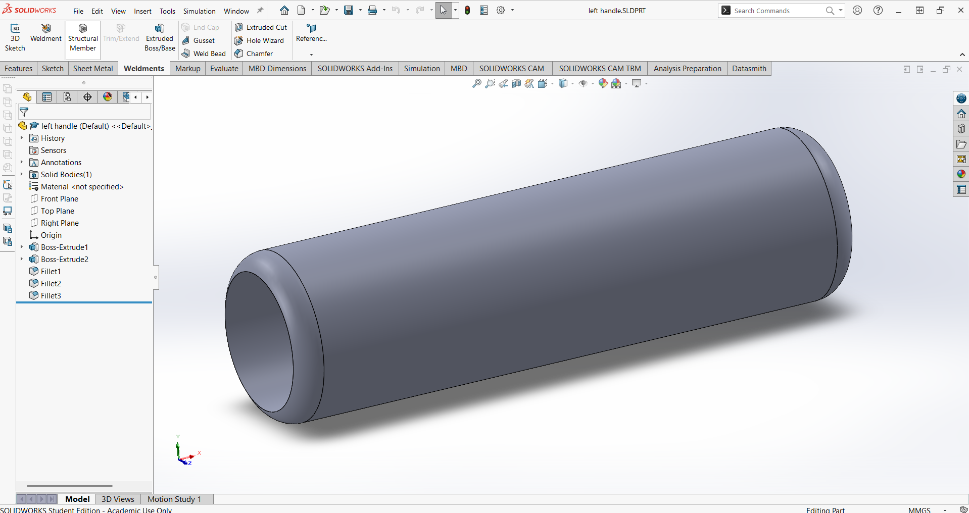
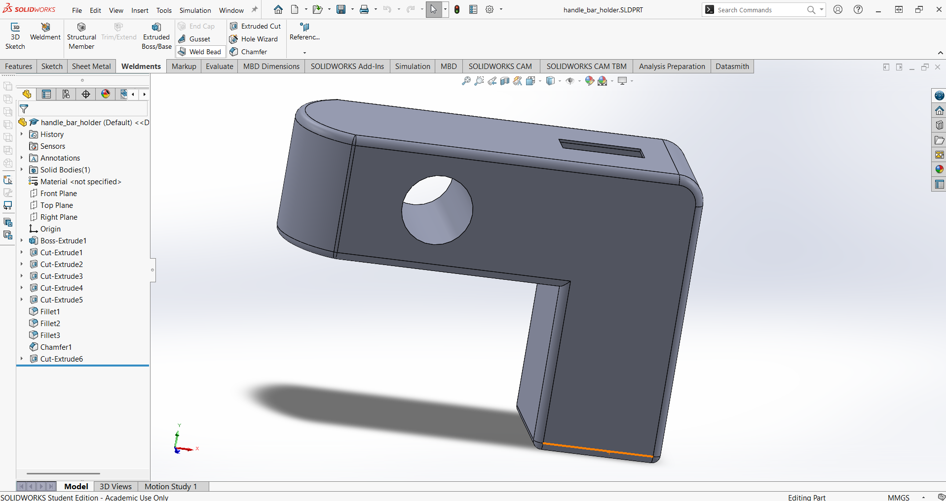
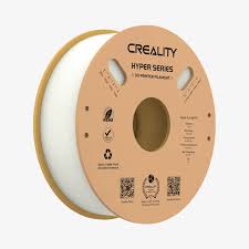
All 3D printed parts were sliced using Creality Print and printed on a Creality Ender 3 V3 plus printer. I iterated the designs based on fit and function, updating the models as needed.
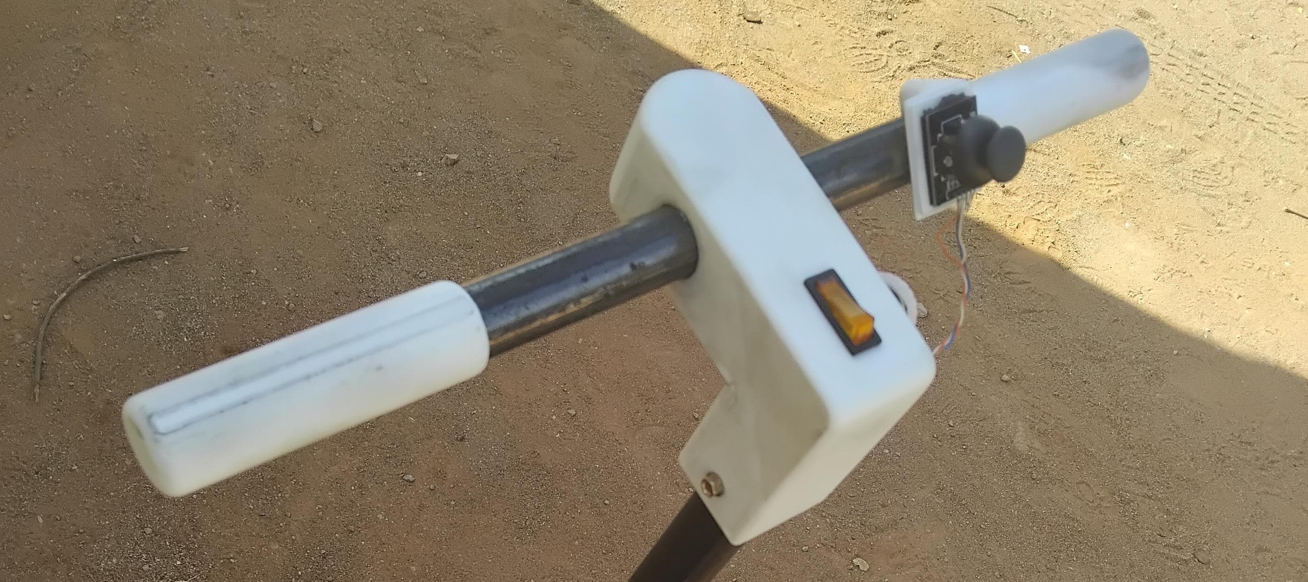
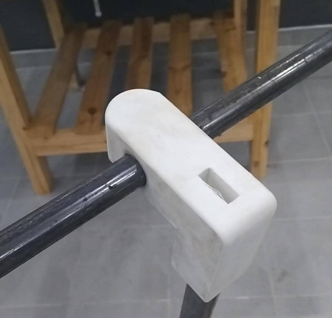
Below is an image showing the assembled left and right handles, along with the 3D printed bracket, mounted on the scooter's steering shaft. This demonstrates the final fit and integration of the custom-designed components.
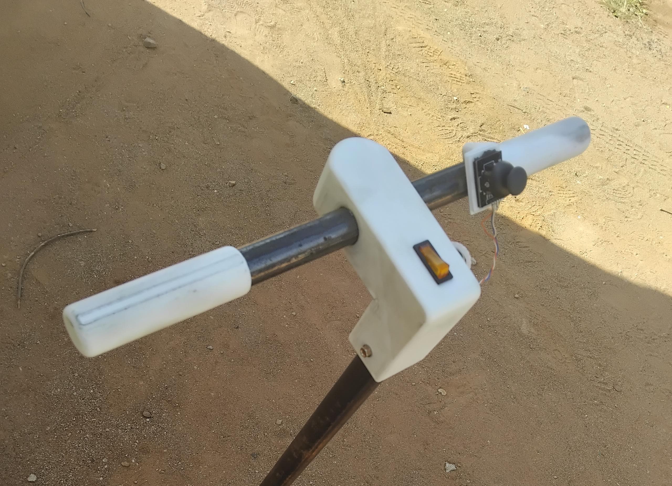
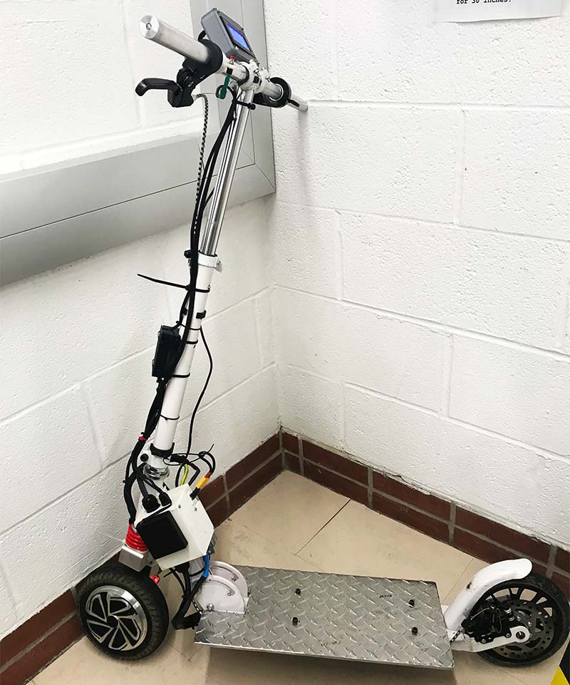
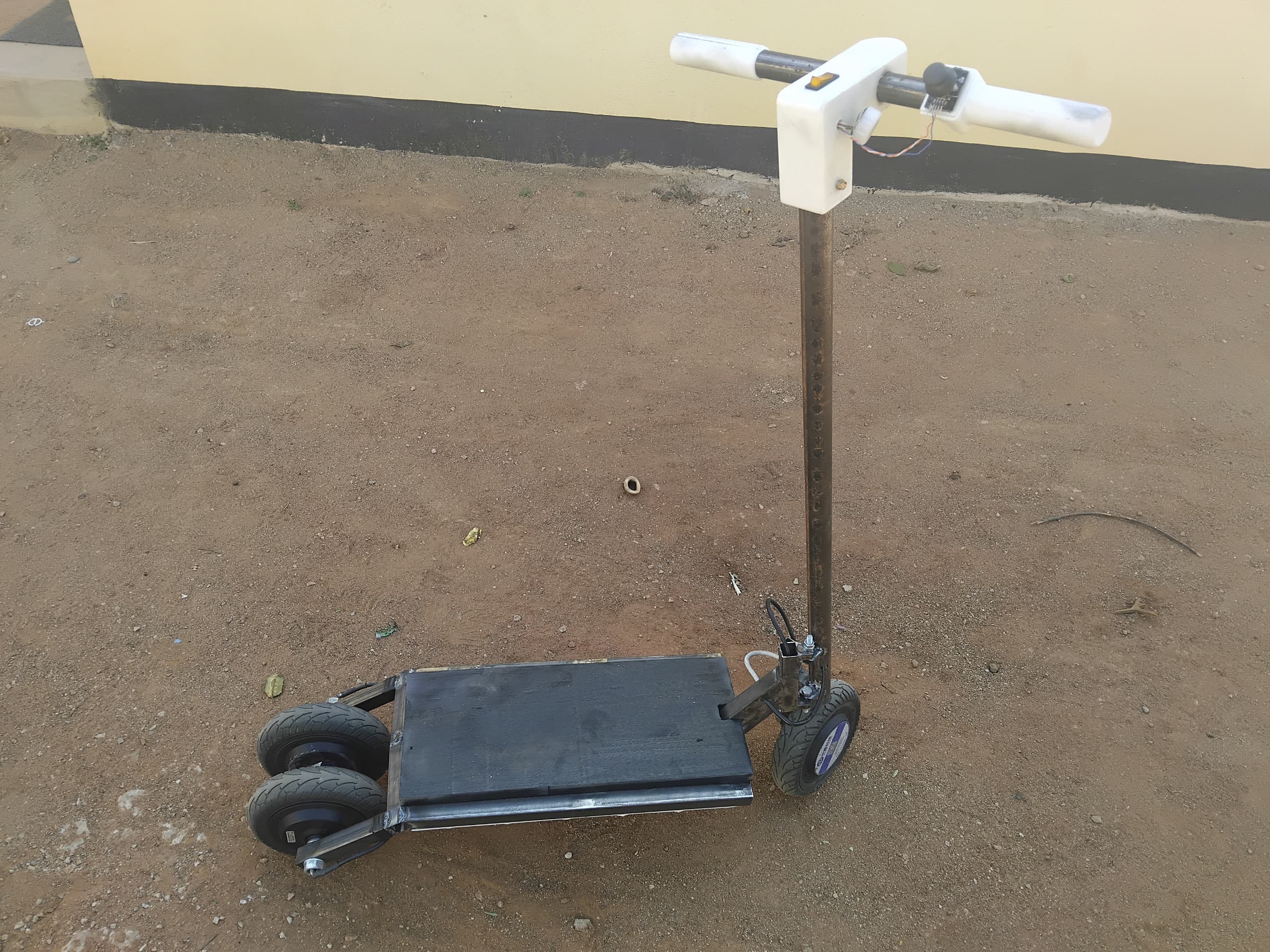
Below is an image of the fully assembled electric scooter, showcasing the integration of all fabricated parts and systems. For a detailed walkthrough of the system integration process—including wiring, electronics, and final testing—see the System Integration page.
Below is the final Arduino program used to control the electric scooter via Modbus RTU over RS485. This code handles communication with the motor driver, processes throttle input, and manages safety features.
// Final Electric Scooter Program
#include <ModbusMaster.h>
#include <Wire.h>


bool isDebugMode = false;         // Set to true for debugging, false for normal operation

const int throttle = D2;
const int maxSpeed = 250;

// Calibrated values from testing
const int joyMin = 0;             // Lowest value when pushed fully down
const int joyCenter = 2270;       // Value when joystick is at rest
const int joyMax = 4095;          // Highest value when pushed fully up

const int deadZone = 50;          // Adjust this if needed (20–100 works well)

// Filtering variables
float filteredThrottle = joyCenter;   // Start at center
const float filterStrength = 0.2;     // 0.0 (no filter) to 1.0 (heavy filter)


// Constants for MAX485 RS485 Transceiver
#define MAX485_DE           D9
#define MAX485_RE_NEG       D8

// Velocity control mode registers for the motor driver
// These registers are used to control the motor driver and read its status.
#define CONTROL_WORD 0x200E
#define CONTROL_MODE 0x200D

#define ACCELERATION_TIME_LEFT    0x2080
#define ACCELERATION_TIME_RIGHT   0x2081
#define DECELERATION_TIME_LEFT    0x2082
#define DECELERATION_TIME_RIGHT   0x2083

#define TARGET_VELOCITY_LEFT      0x2088
#define TARGET_VELOCITY_RIGHT     0x2089
#define ACTUAL_VELOCITY_LEFT      0x20AB
#define ACTUAL_VELOCITY_RIGHT     0x20AC

// Settings for the motor driver (CONTROL_WORD values)
const uint16_t QUICK_STOP   = 0x05;
const uint16_t CLEAR_FAULT  = 0x06;
const uint16_t STOP         = 0x07;
const uint16_t ENABLE       = 0x08;

// needed in position control
const uint16_t START        = 0x10;  // SYNC
const uint16_t START_LEFT   = 0x11;  // ASYNC
const uint16_t START_RIGHT  = 0x12;  // ASYNC

const uint16_t ACCELERATION_DECELERATION_TIME = 0; // In milliseconds(ms)

// ModbusMaster object instantiation
ModbusMaster node;

// Function prototypes
// Callback function before transmission
// Callback function after transmission
void preTransmission();
void postTransmission();

// Function to write a single register
// Function to send synchronous move command to both motors
bool writeRegister(uint16_t address, uint16_t value);
bool syncronousMove(int leftVelocity, int rightVelocity);


int16_t leftRPM = 0;
int16_t rightRPM = 0;
int16_t actualVelocityData[2];


bool motorIdle = false;
float currentCommandedSpeed = 0;
float rampRate = 5; // RPM per loop iteration (tune this value)


void setup() {
    pinMode(throttle, INPUT);
    pinMode(MAX485_RE_NEG, OUTPUT);
    pinMode(MAX485_DE, OUTPUT);

        // Init in receive mode
    digitalWrite(MAX485_RE_NEG, 0);
    digitalWrite(MAX485_DE, 0);

    Serial.begin(115200);
    Serial1.begin(115200, SERIAL_8N1, 20, 21);

    // Modbus slave ID 1
    node.begin(1, Serial1);
    // Callbacks allow us to configure the RS485 transceiver correctly
    node.preTransmission(preTransmission);
    node.postTransmission(postTransmission);

       // System start with default as Velocity mode
    Serial.println("connecting to servo driver...");

   while(true){
    // start by handshaking with the motor driver
    if (writeRegister(CONTROL_WORD, CLEAR_FAULT) &&
        writeRegister(CONTROL_WORD, STOP) &&
        writeRegister(CONTROL_MODE, 0x03) &&
        writeRegister(ACCELERATION_TIME_LEFT, ACCELERATION_DECELERATION_TIME) &&
        writeRegister(ACCELERATION_TIME_RIGHT, ACCELERATION_DECELERATION_TIME) &&
        writeRegister(DECELERATION_TIME_LEFT, ACCELERATION_DECELERATION_TIME) &&
        writeRegister(DECELERATION_TIME_RIGHT, ACCELERATION_DECELERATION_TIME)) {

      Serial.println("Motor driver is Listening...");
      motorIdle = true;
      //isMotorDriverOnline = true;
      delay(500);
      break;
    }else{
      Serial.println("Reaching out to Motor driver...");
    }
    delay(1000);
  }


}


/*
  * The loop function is where the main logic of the program runs.
  * In this case, it reads the throttle input, processes it, and sends commands to the motor driver.
  * The RideMode() function handles the main control logic for the scooter.
  */
void loop() {

  if(isDebugMode){
    debugMode();
  }else{
    RideMode();
  }

  delay(50); // Tighter loop for smoother response
}


/*  * RideMode() function handles the main control logic for the scooter.
  * It reads the throttle input, applies filtering, maps it to RPM, and sends commands to the motor driver.
  * It also manages idle state and smooth ramping of speed.
  */
void RideMode() {
  int rawThrottle = analogRead(throttle);

  // Exponential smoothing
  filteredThrottle = (filterStrength * rawThrottle) + ((1.0 - filterStrength) * filteredThrottle);

  int adjustedThrottle = 0;

  // Joystick to RPM mapping
  if (filteredThrottle > joyCenter + deadZone) {
    adjustedThrottle = map(filteredThrottle, joyCenter + deadZone, joyMax, 0, -maxSpeed);
  } else if (filteredThrottle < joyCenter - deadZone) {
    adjustedThrottle = map(filteredThrottle, joyMin, joyCenter - deadZone, maxSpeed, 0);
  } else {
    adjustedThrottle = 0;
  }

  // Constrain the adjusted throttle to the maximum speed
  adjustedThrottle = constrain(adjustedThrottle, -maxSpeed, maxSpeed);

  if(adjustedThrottle < 0){
    adjustedThrottle = 0;
  }

  // Read actual velocity from motors
  getActualVelocityLR(); // Updates leftRPM and rightRPM
  float averageSpeed = (leftRPM + rightRPM) / 2.0;

  // === Idle logic ===
  if (adjustedThrottle == 0 && abs(averageSpeed) > 0) {
    if (!motorIdle) {
      writeRegister(CONTROL_WORD, 0x07); // Disable motors
      motorIdle = true;
    }
  }
  else {
    // Re-engage motor
    if (motorIdle && abs(adjustedThrottle) > 50) {
      currentCommandedSpeed = averageSpeed; // Preload current speed

      // Write speed to initial velocity register
      writeInitialVelocityBoth(currentCommandedSpeed, currentCommandedSpeed);
      syncronousMove(currentCommandedSpeed, currentCommandedSpeed);
      delay(30); // Optional buffer delay

      // Re-enable motors
      writeRegister(CONTROL_WORD, 0x08);
      motorIdle = false;
    }

    // Smooth ramping
    if (!motorIdle) {
      if (abs(adjustedThrottle - currentCommandedSpeed) > rampRate) {
        if (adjustedThrottle > currentCommandedSpeed) {
          currentCommandedSpeed += rampRate;
          //delay(100);
        } else {
          currentCommandedSpeed -= rampRate;
          //delay(100);
        }
      } else {
        currentCommandedSpeed = adjustedThrottle;
      }

      // Send speed to both motors
      syncronousMove(currentCommandedSpeed, currentCommandedSpeed);
    }
  }

  // Debug print
  Serial.print("Raw: ");
  Serial.print(rawThrottle);
  Serial.print(" | Filtered: ");
  Serial.print(filteredThrottle);
  Serial.print(" | TargetSpeed: ");
  Serial.print(adjustedThrottle);
  Serial.print(" | AvgRPM: ");
  Serial.print(averageSpeed);
  Serial.print(" | CmdSpeed: ");
  Serial.print(currentCommandedSpeed);
  Serial.print(" | Idle: ");
  Serial.println(motorIdle);
}


/*  * debugMode() function is used for debugging purposes.
  * It reads a specific register from the motor driver and prints its value.
  * This can help verify communication and register values during development.
  */
void debugMode(){
  uint16_t result = node.readHoldingRegisters(0x2043, 1);

  if (result == node.ku8MBSuccess) {
    uint16_t value = node.getResponseBuffer(0);
    Serial.print("Register value: ");
    Serial.println(value);
  } else {
    Serial.print("Error reading register: ");
    Serial.println(result);
  }

  delay(500);
}

// ----------------------------------------
// Helper to write initial velocity register
void writeInitialVelocityBoth(int leftVelocityRPM, int rightVelocityRPM) {
  // Adjust scaling if your motor expects 0.1 RPM (multiply by 10)
  int leftScaled = leftVelocityRPM;
  int rightScaled = rightVelocityRPM;

  uint8_t resultLeft = node.writeSingleRegister(0x2043, leftScaled);
  if (resultLeft != node.ku8MBSuccess) {
    Serial.print("Left motor init velocity write error: ");
    Serial.println(resultLeft);
  }

  uint8_t resultRight = node.writeSingleRegister(0x2073, rightScaled);
  if (resultRight != node.ku8MBSuccess) {
    Serial.print("Right motor init velocity write error: ");
    Serial.println(resultRight);
  }
}

/*  * getActualVelocityLR() function reads the actual velocity of both motors.
  * It uses Modbus to read the holding registers for left and right motor velocities.
  * The velocities are stored in the actualVelocityData array and converted to RPM.
  * The left motor's RPM is negated to match the expected direction.
  */
void getActualVelocityLR(){
  int size = 2;
  uint8_t j, result;
  result = node.readHoldingRegisters(0x20AB, 2);

  if(result == node.ku8MBSuccess){
    for (j = 0; j<size; j++){
      uint16_t mVal = node.getResponseBuffer(j);
      actualVelocityData[j] = *((int16_t*)&mVal);
      actualVelocityData[j] = actualVelocityData[j]*0.1;
    }

    leftRPM = -actualVelocityData[0];
    rightRPM = actualVelocityData[1];
  }
}


// Callback function before transmission
void preTransmission() {
    digitalWrite(MAX485_RE_NEG, 1);
    digitalWrite(MAX485_DE, 1);
}

// Callback function after transmission
void postTransmission() {
    digitalWrite(MAX485_RE_NEG, 0);
    digitalWrite(MAX485_DE, 0);
}

bool writeRegister(uint16_t address, uint16_t value) {
  return node.writeSingleRegister(address, value) == 0;
}


bool syncronousMove(int leftVelocity, int rightVelocity){
  node.setTransmitBuffer(0, -leftVelocity);
  node.setTransmitBuffer(1, rightVelocity);

  return node.writeMultipleRegisters(0x2088, 2);
}
I used 3D printing to fabricate custom enclosures, handlebar grips, brackets, and holders for the electronics and battery. This process allowed for rapid prototyping and precise fitting of parts. Models were designed in CAD software and printed using PLA filament on a Creality Ender 3 V3 Plus printer.
The custom circuit board was produced using PCB isolation milling. I designed the PCB in KiCad, generated toolpaths in CopperCAM, and milled the board on a Bungard CCD machine. This process removes unwanted copper from a copper-clad board, creating isolated traces for the circuit without using chemical etching.
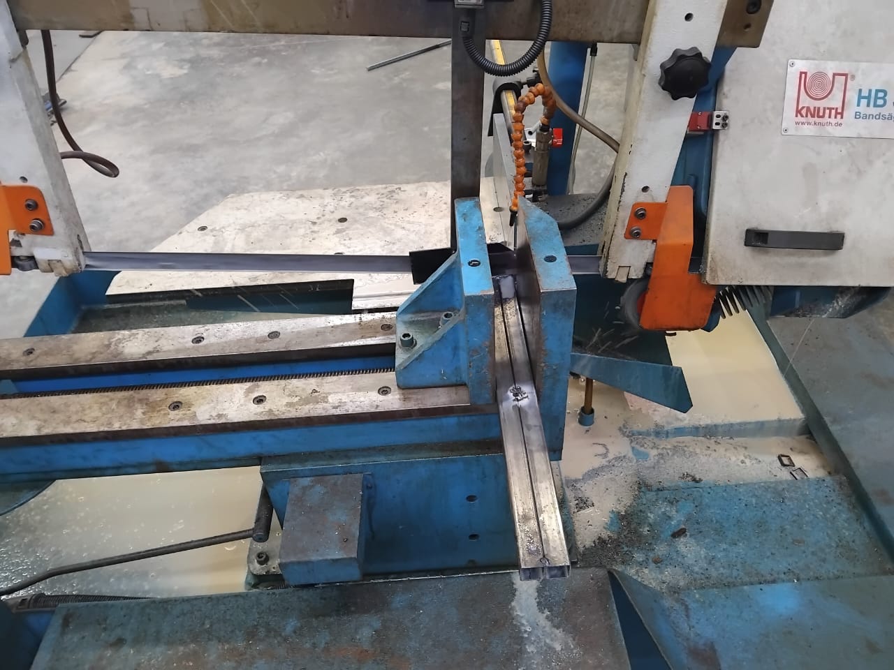
The scooter frame was built from mild steel square tubing. I cut the tubes to size using a hacksaw and mechanical saw, then welded the pieces together using MIG welding. This provided a strong and durable structure for the scooter.
Arc welding was used to join steel components of the scooter frame. This process involved using an electric arc to melt and fuse the metal at the joints, ensuring strong and permanent connections for structural integrity.
After milling the PCB, I soldered all electronic components by hand, including microcontrollers, connectors, resistors, and capacitors. Careful soldering ensured reliable electrical connections and robust operation of the control system.
The development process involved several iterations, especially with the custom PCB for the motor driver interface. I fabricated two PCBs that did not work before succeeding on the third attempt.
In my first PCB design, I powered several ICs (such as the MAX485 and ACS712 current sensor IC) with 5V, while the Xiao ESP32-C3 microcontroller operates at 3.3V logic. This caused the outputs from these ICs to exceed the safe input voltage for the ESP32-C3’s pins.
However, the ACS712 current sensor IC required a 5V supply. To safely read its analog output with the ESP32-C3, I used a voltage divider to reduce the sensor’s output voltage to a safe level for the microcontroller’s ADC input.
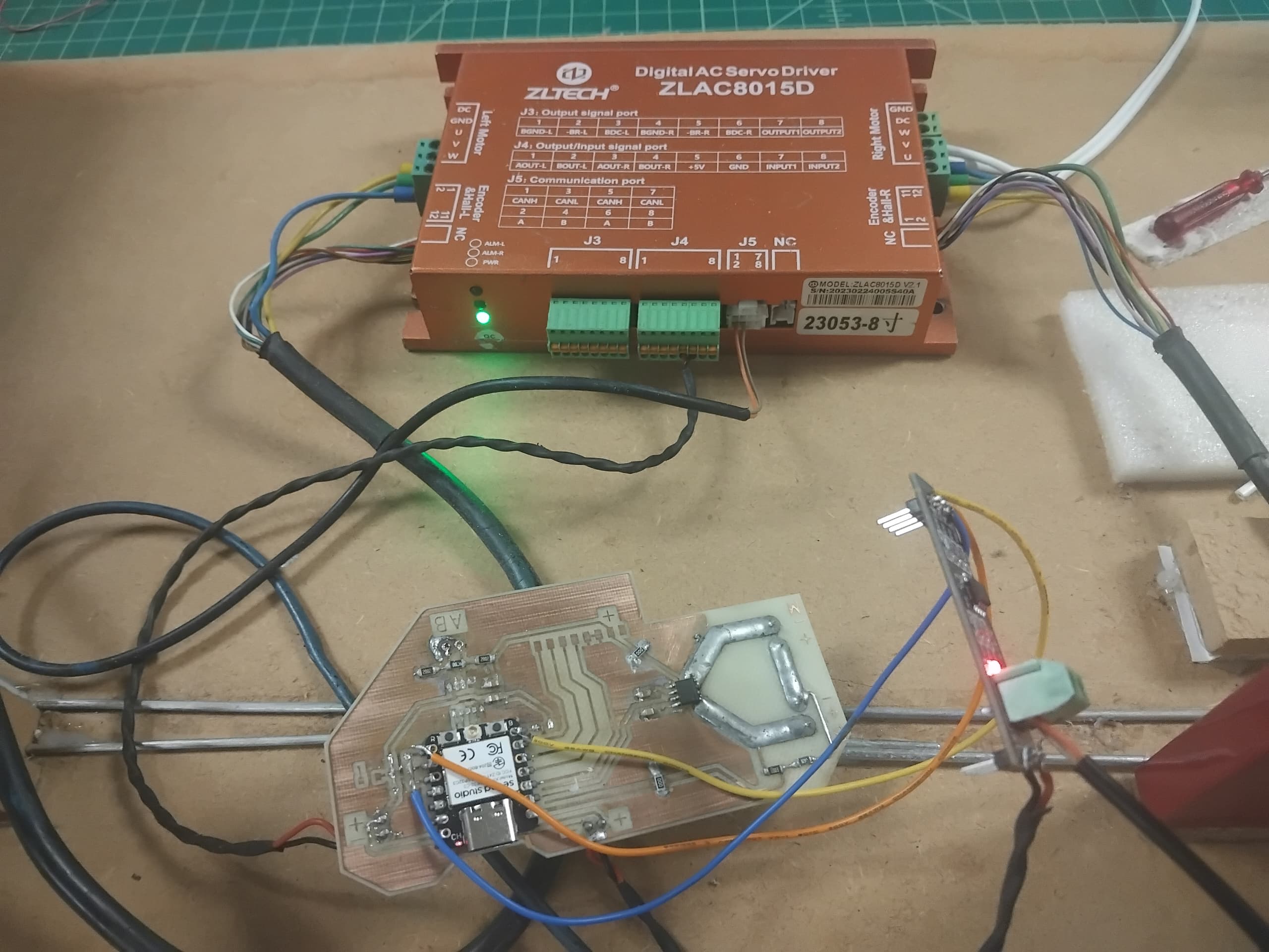
After correcting the logic level issue and building a second PCB, I encountered another problem: the MAX485 transceiver was not communicating. Upon inspection, I realized I had swapped the RX and TX lines between the microcontroller and the MAX485, preventing any data transmission.
To confirm that the issue was indeed swapped RX and TX lines, I hard-soldered an external RS485 module directly to the board and connected it to the controller. This time, I received a response from the motor driver, proving that the communication lines were the problem. With this confirmation, I went back to KiCad and corrected the RX/TX routing in my PCB design before fabricating the next revision.
On the third attempt, I corrected both the logic level and RX/TX wiring issues. The PCB worked as intended, allowing reliable communication between the ESP32-C3 and the motor driver.
These challenges taught me the importance of carefully checking voltage compatibility and signal routing in mixed-voltage systems, as well as the value of iterative prototyping and thorough testing.
Overall, the project met its core goals for rideability, safety, and basic range. Future work will focus on extending range, refining the user interface, and adding more advanced features.
The development of my electric scooter project demonstrates the potential for sustainable, accessible, and locally manufactured personal transportation. By designing and fabricating the scooter structure myself, I was able to tailor the frame for lightweight portability and urban use. The use of BLDC motors, paired with a commercial controller, allowed for efficient power delivery and reliable performance.
A key implication of this project is its contribution to sustainable transport solutions. Electric scooters offer a clean alternative to fossil-fuel vehicles for short commutes, helping to reduce urban congestion and air pollution. By documenting the fabrication process and sharing design files, I hope to encourage local manufacturing and empower others to build or adapt similar vehicles using accessible digital fabrication tools.
Building a custom interface to control the BLDC motor controller was both challenging and rewarding. It provided hands-on experience with embedded systems and user interface design. In future iterations, I would focus on improving the integration between the controller and the dashboard, possibly adding wireless connectivity for remote monitoring and diagnostics. I would also explore optimizing the frame design for even greater durability and ease of assembly.
One significant area for improvement is implementing regenerative braking, which I have not yet achieved. Adding this feature in the future could further increase energy efficiency. Additionally, as I gain more experience in electronics design, I plan to build my own BLDC motor controller to replace the commercial unit, allowing for deeper customization and learning. Developing a more advanced battery management system (BMS) would also enhance safety and extend the scooter's lifespan.
All design files, code, and documentation are openly shared to enable others to replicate, modify, or build upon this project. The modular approach to the scooter's electronics and structure makes it adaptable for different needs or environments. I encourage others to experiment with alternative materials, motor types, or control interfaces, and to contribute improvements back to the community. Through collaboration and open-source sharing, projects like this can accelerate the adoption of sustainable transport and digital fabrication skills worldwide.
All files are provided under a Creative Commons Attribution Non Commercial license.
I would like to acknowledge the Fab Academy for providing this incredible opportunity to learn and grow in digital fabrication.
Special thanks to my sponsors for their generous support throughout this journey.
I am also deeply grateful to my instructor for their guidance, encouragement, and expertise.