For this week, I focused on designing and documenting the system integration for my final project. System integration involves connecting all the individual subsystems—such as electronics, mechanical components, and software—into a cohesive and functional whole.
Defining System Integration
System integration is the process of bringing together various components and subsystems so that they work together as a unified system. In the context of my final project, this means ensuring that the microcontroller, sensors, actuators, power supply, and user interface communicate and operate seamlessly.
Application to My Final Project
Electronics: Connected the microcontroller to input sensors and output devices, ensuring correct wiring and signal flow.
Software: Developed and uploaded firmware that manages sensor readings, processes data, and controls actuators based on logic.
Mechanical: Integrated all hardware components into the project enclosure, ensuring accessibility and stability.
Power: Designed a power distribution system to safely supply all components.
Testing: Verified that all subsystems interact correctly and the overall system meets the project requirements.
Through this process, I learned how to define system integration and apply it to my final project, resulting in a fully functional prototype.
Detailed System Integration for the Scooter Project
Overview
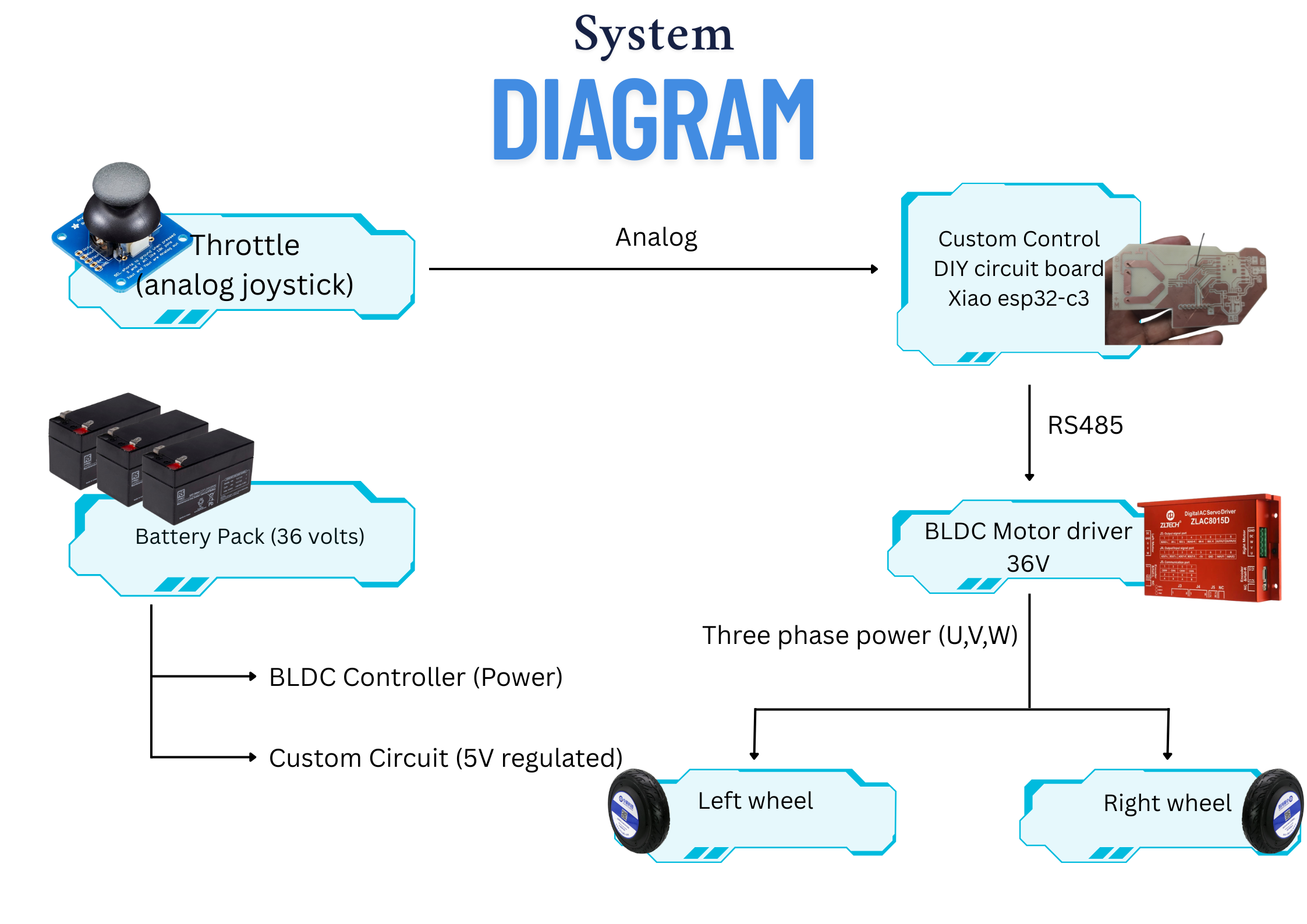
For my final project, I am designing an electric scooter that integrates mechanical, electrical, and software subsystems. The system is powered by three 12V batteries connected in series to provide 36V to the motor. The core of the system is a custom PCB designed in KiCad, featuring the Xiao ESP32C3 microcontroller, which manages communication and control.
System Integration Diagram
Figure: Block diagram showing the integration of power, control, and communication subsystems in the electric scooter project.
Power System
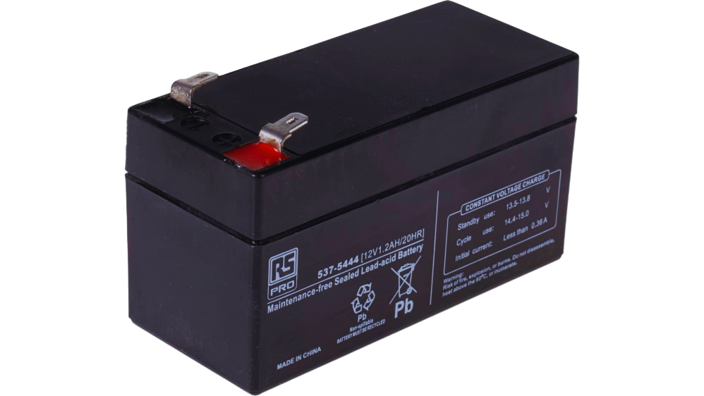
Figure: 12V 7.2Ah sealed lead acid battery used for the scooter's power system.
Batteries: Three 12V batteries are connected in series, supplying a total of 36V to the motor driver. This configuration ensures sufficient voltage and current for the scooter's brushless DC hub motor.
Power Distribution: The Zltech servo driver includes a built-in 5V output, which is used to power the custom control board, simplifying the power architecture and reducing the need for additional voltage regulators.
Motor and Motor Driver
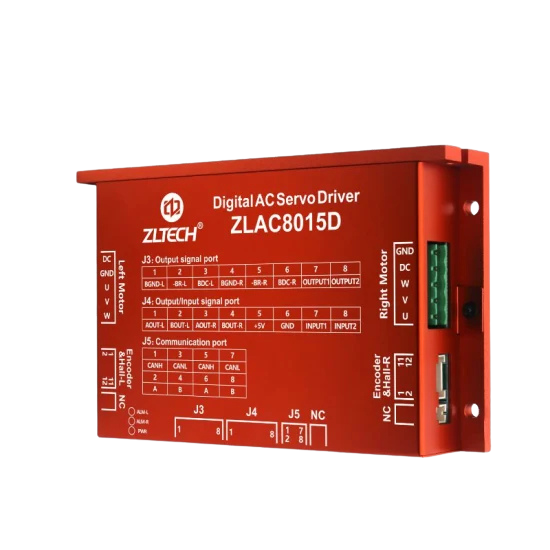
Figure: Zltech Dual Channel Servo Motor Driver used for controlling the scooter's brushless DC hub motor.
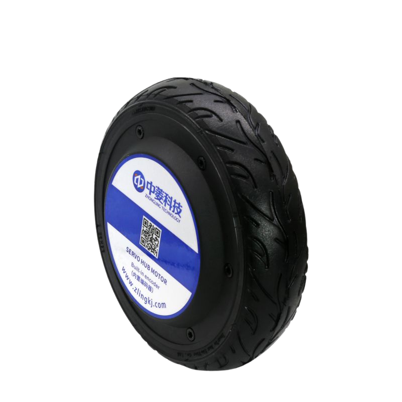
Figure: Brushless DC hub motor integrated into the scooter's wheel for efficient propulsion.
Motor Driver: The Zltech Dual Channel CANopen RS485 Modbus 3 Phase 24V/48V 30A 500W Brushless DC Hub Servo Driver is used to control the scooter's motor. It supports advanced communication protocols (RS485 Modbus) for reliable and precise control.
Motor: A brushless DC hub motor is used for propulsion, offering high efficiency and torque suitable for scooter applications.
Custom Control Board
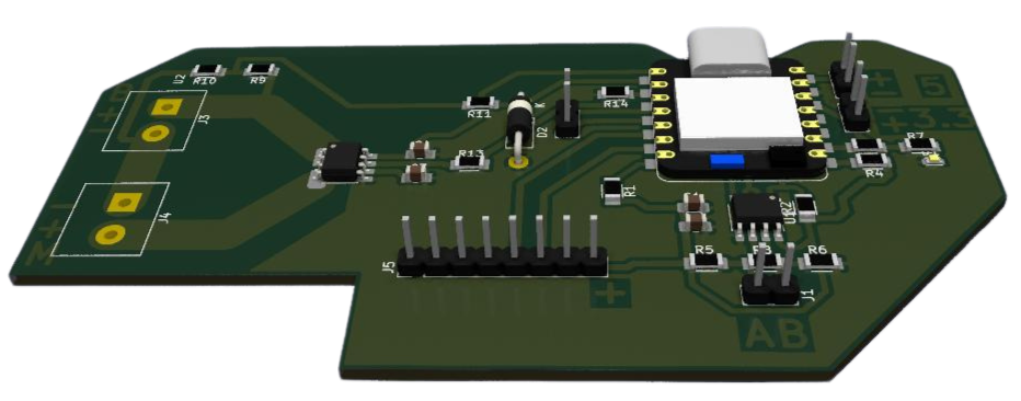
Figure: Render of the custom control board designed for the scooter project, featuring the Xiao ESP32C3 and MAX485 circuit.
Microcontroller: The custom PCB is built around the Xiao ESP32C3, chosen for its compact size, integrated WiFi and Bluetooth, and low power consumption.
RS485 Communication: The board includes a MAX485 circuit, enabling robust RS485 Modbus communication with the motor driver. This allows the ESP32C3 to send throttle and brake commands and receive status feedback from the driver.
Power Supply: The 5V output from the servo driver powers the ESP32C3 and associated circuitry, ensuring stable operation.
Analog Joystick Control
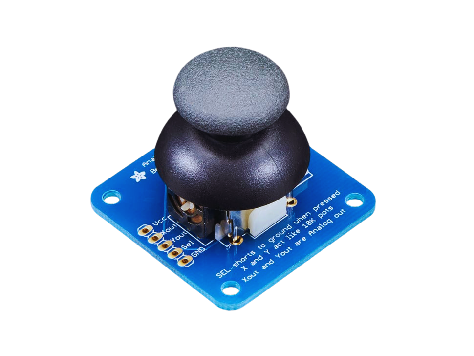
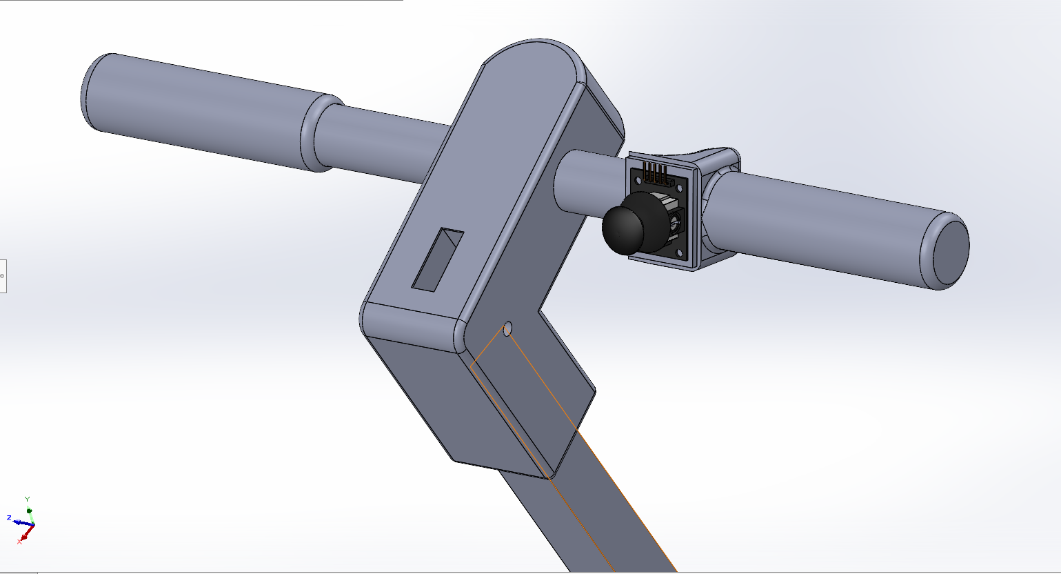
Figure: Analog joystick currently used for throttle input.
Figure: Ideal scooter throttle with integrated handlebar grip and hall sensor.
Analog Throttle Input: The scooter now uses a wired analog joystick to provide throttle input. The joystick outputs a variable voltage corresponding to the throttle position, which is read by the ESP32C3's analog input pin.
Direct and Reliable Control: This wired setup ensures immediate and reliable throttle response, eliminating wireless latency and potential connectivity issues.
Integration Process
Video Demonstration: Integration Process
Video: Demonstration of connecting all subsystems together on a test rig, showing the integration of power, control, and communication components for the electric scooter project.
PCB Design and Assembly: Designed the custom control board in KiCad, integrating the ESP32C3 and MAX485 for communication. Assembled and tested the board for correct operation.
Wiring and Connections: Connected the batteries, motor driver, and custom board, ensuring correct voltage levels and secure connections.
Firmware Development: Programmed the ESP32C3 to handle wireless input, process throttle and brake commands, and communicate with the motor driver via RS485 Modbus.
System Testing: Verified communication between the wireless controller and the main board, and between the main board and the motor driver. Tested the scooter under load to ensure all subsystems work together seamlessly.
System Packaging
For the packaging phase of system integration, I focused on designing a robust and functional structure for the electric scooter. The main frame was constructed using mild steel, chosen for its strength, durability, and ease of fabrication. This provided a solid foundation capable of supporting the weight of the rider and all integrated components.
Frame Design: The scooter's chassis was designed in CAD and fabricated from mild steel tubing and plates. The design ensures structural integrity while allowing for mounting points for the motor, batteries, and wheels.
3D Printed Enclosures: To securely house the electronics and accessories, I designed custom 3D printed enclosures. These enclosures protect the control board, wiring, and connectors from dust, vibration, and accidental contact, while also providing easy access for maintenance.
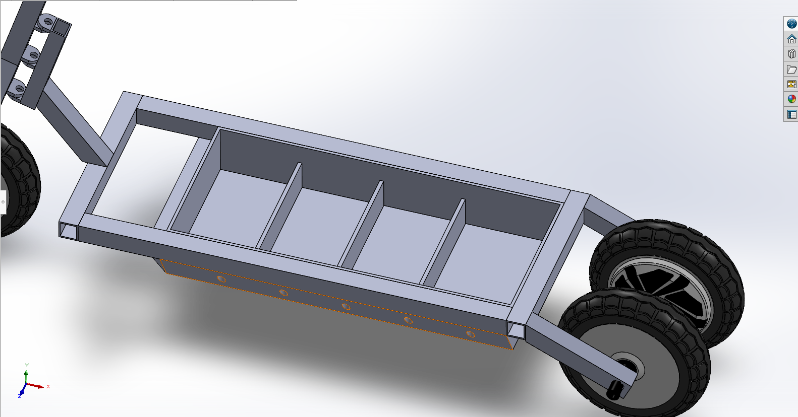
Figure: CAD render showing dedicated compartments for batteries and electronic circuits within the scooter frame.
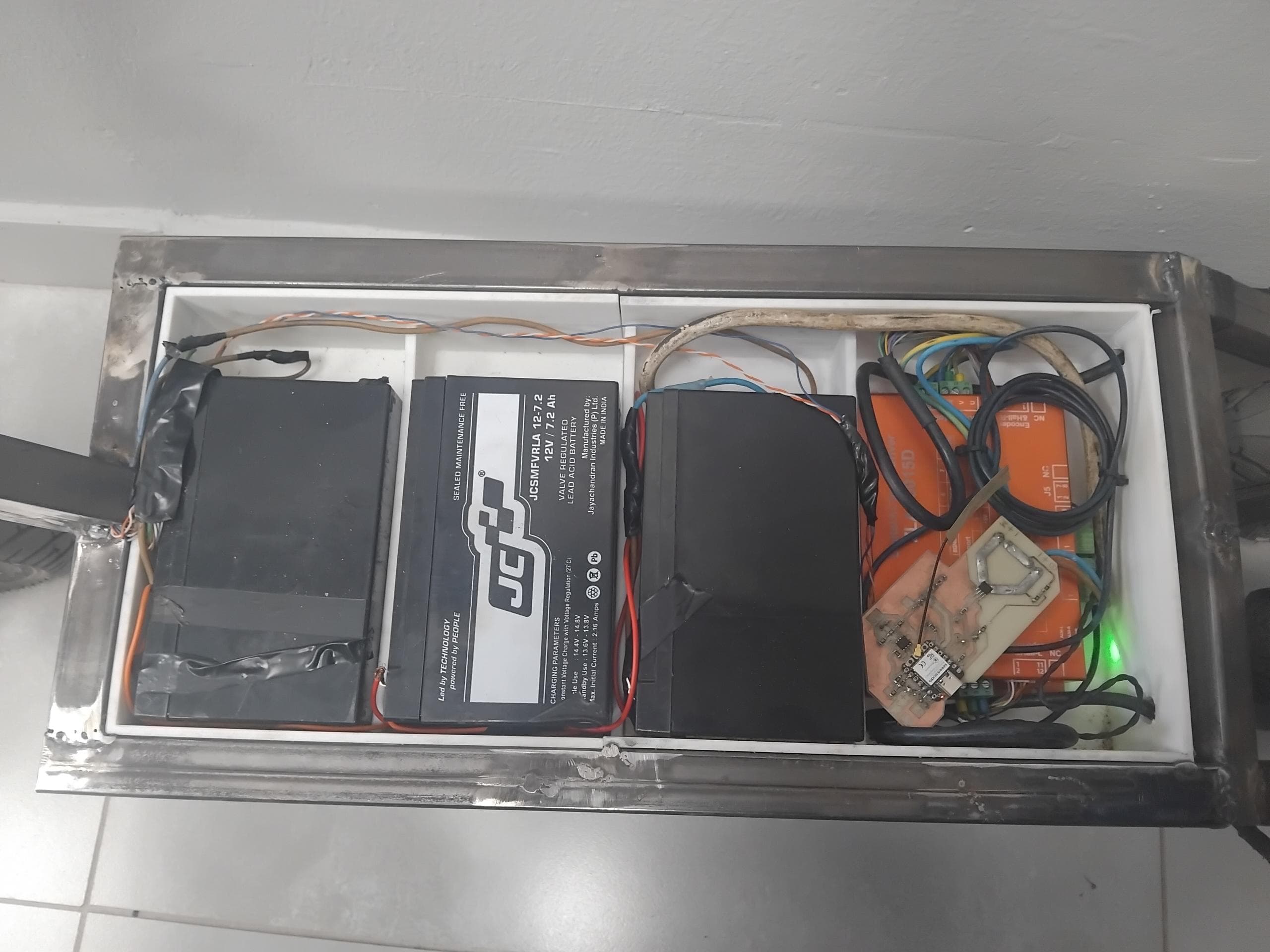
Bellow is an image of all comonents securly fit in their compartmenst holding them securely in place.
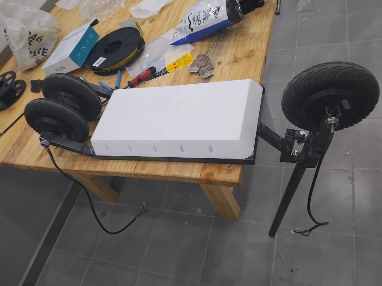
Figure: All components securely fitted in their respective compartments within the scooter frame, showcasing the organized layout.
Accessory Mounts: Additional 3D printed parts were created for mounting accessories such as the throttle, display, and lighting modules, ensuring a clean and organized assembly.
Figure: CAD render highlighting the accessory mounts and the position of the joystick throttle on the scooter's handlebar assembly.
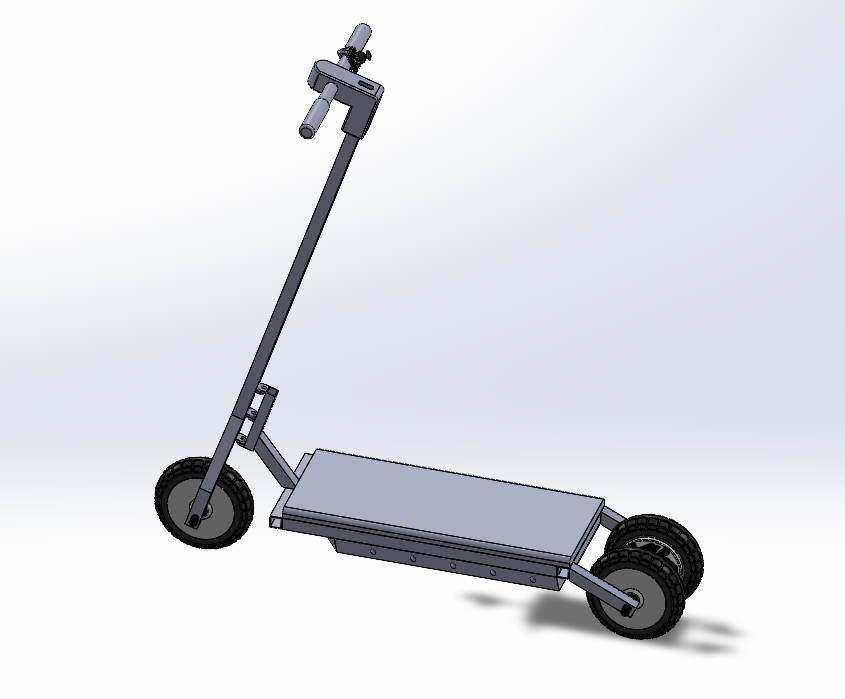
Figure: Final CAD assembly showing the mild steel frame and 3D printed enclosures for the scooter's components.
This approach to system packaging not only enhances the durability and safety of the scooter but also streamlines the integration of all subsystems, resulting in a professional and reliable prototype.
Assembly Process
The assembly process involved carefully mounting and connecting all major components within the scooter frame. This included securing the batteries, installing the motor and driver, and integrating the custom control board and wiring harnesses.
Figure: Assembling the main scooter frame and mounting the battery compartment.
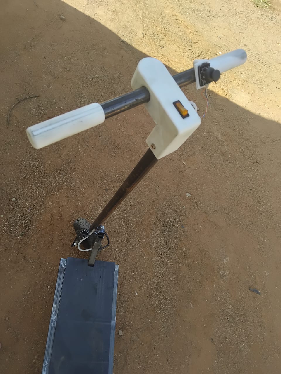
Figure: Integrating the switches and throttle.
Each step was documented to ensure proper alignment, secure connections, and ease of future maintenance. The result is a robust and organized assembly, ready for system testing.
Video Demonstration: Load Test
Video: Load test of the electric scooter, demonstrating performance under real-world riding conditions.
Testing and Validation
After integrating all subsystems, I conducted thorough testing and validation to ensure the electric scooter operates safely and reliably under various conditions.
Video Demonstration: System Testing
Video: Demonstration of the electric scooter undergoing functional and load testing after full system integration.
Functional Testing: Verified that each subsystem (power, control, communication, and mechanical) works as intended both independently and as part of the complete system.
Integration Testing: Checked the interaction between the microcontroller, motor driver, and throttle input to confirm seamless communication and response.
Load Testing: Operated the scooter under different loads and speeds to assess the performance of the motor, batteries, and control electronics.
Safety Validation: Inspected wiring, enclosures, and mounting points for robustness and ensured that all electrical connections are secure and insulated.
Iterative Debugging: Addressed issues such as signal noise, power drops, or communication errors by refining the PCB layout, firmware, and wiring.
The successful completion of these tests confirmed that the system meets the design requirements and is ready for further refinement and real-world use.
Conclusion
Through careful integration of power, control, and communication subsystems, I achieved a functional electric scooter prototype. The use of a custom PCB with wireless capabilities and robust RS485 Modbus communication ensures reliable and flexible control of the motor driver, while the power system provides the necessary energy for efficient operation.