
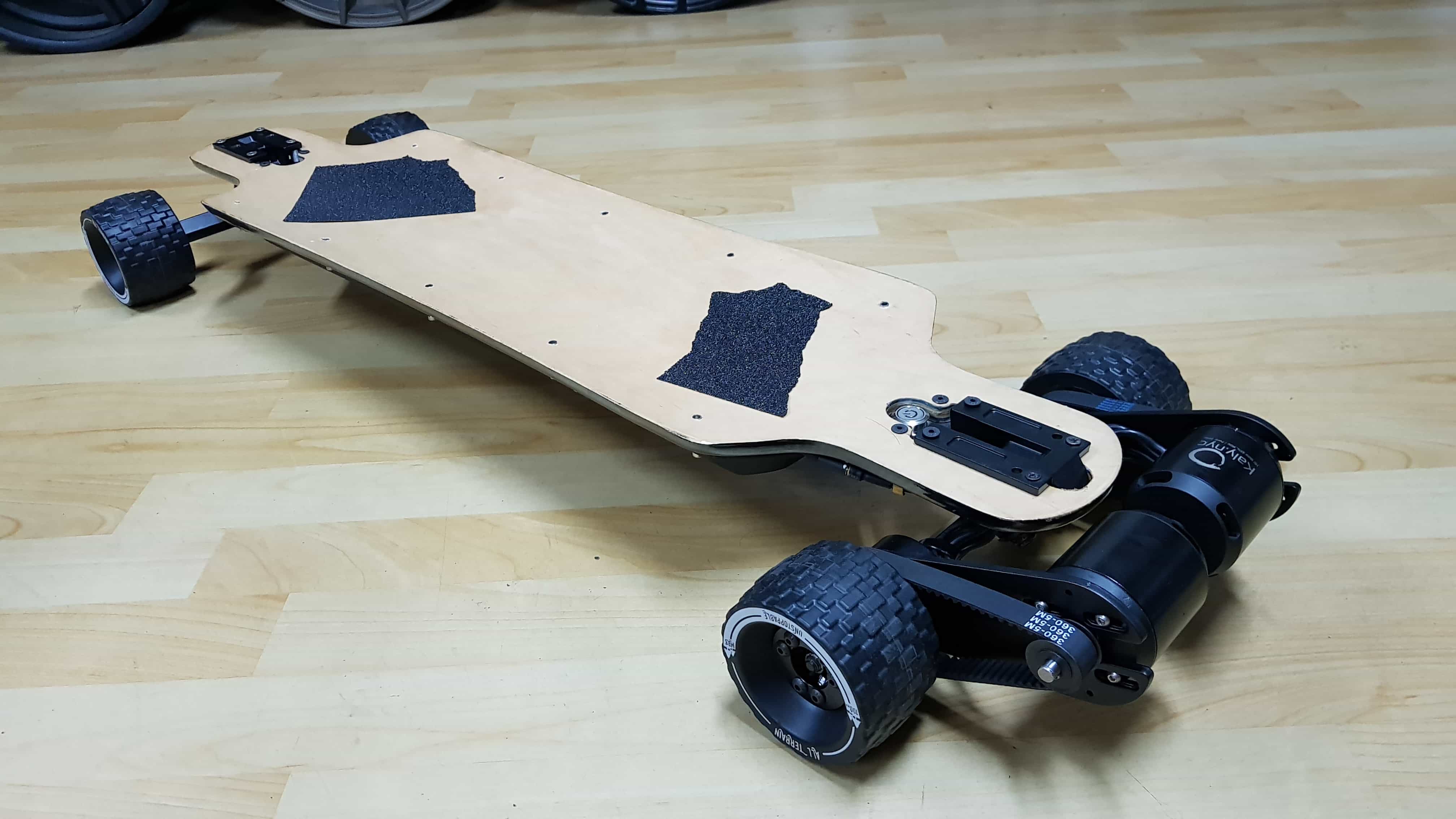
After thinking about my projects for a time I have come to the conclusion that these projects are fine but nothing new or special. I think that there are a lot people that have build arcades or electric longboards. In the last time I was more or less convinced that I would like to make the longboard but I was struggeling in finding unique points for it.
So I changed my idea for the final project again. My new idea which will be my final project is a fully electric powered gokart. The cart will be powered by two brushless motors and a car battery. I want to build a front wheel drive, without having a mechanic steering system. The steering will be completely electronic by using a potentiometer. So to get it to turn I will use a tank-like steering system. When I turn the steering wheel right, the right wheel will turn slower than the left one, what will cause that the cart turns right.
Materials
I am planning on buildung the frame out of wood and make ith stronger by coating it with carbonfiber. I will also try to cast my own wheels for the cart.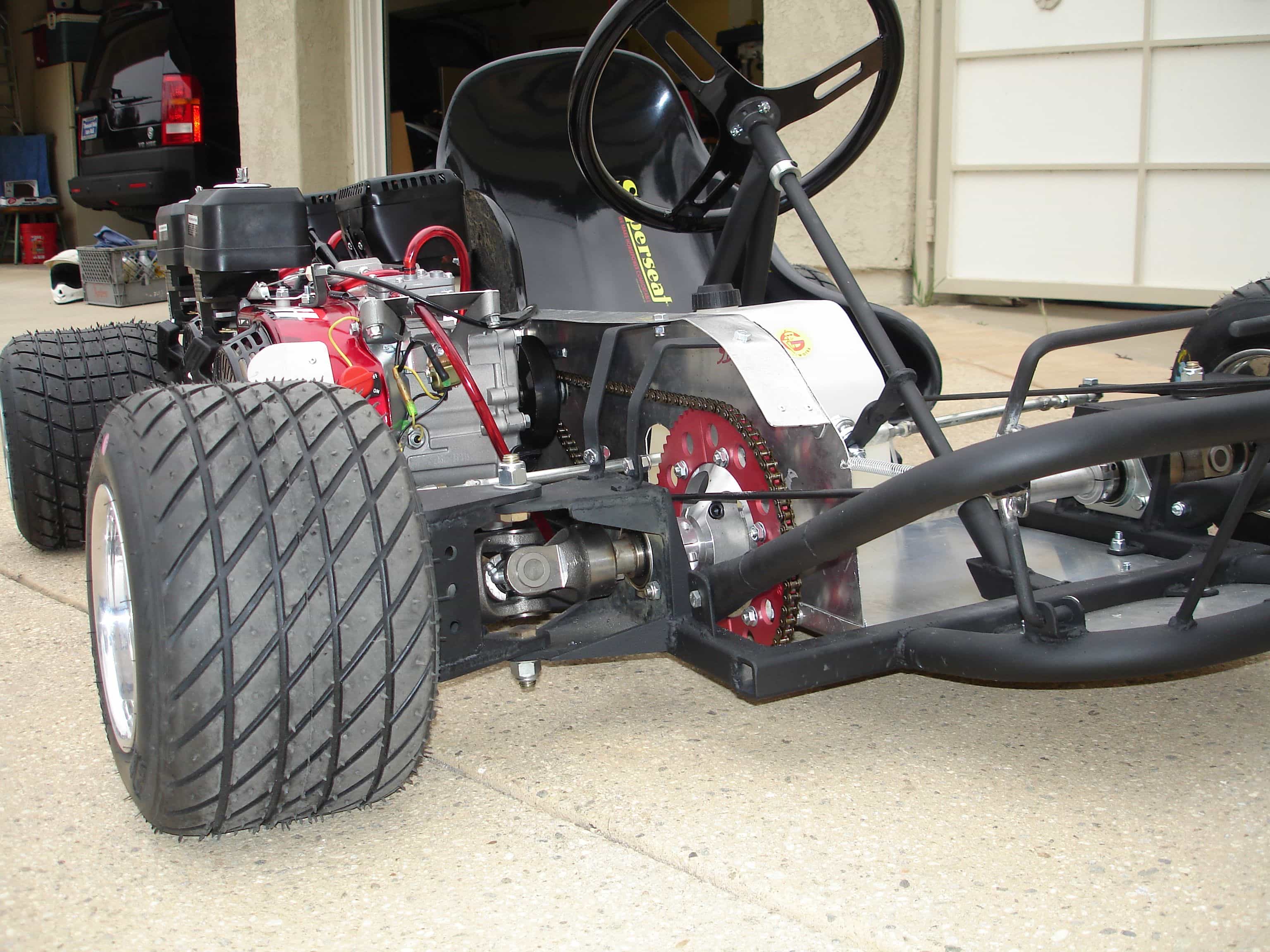
PROGRESS
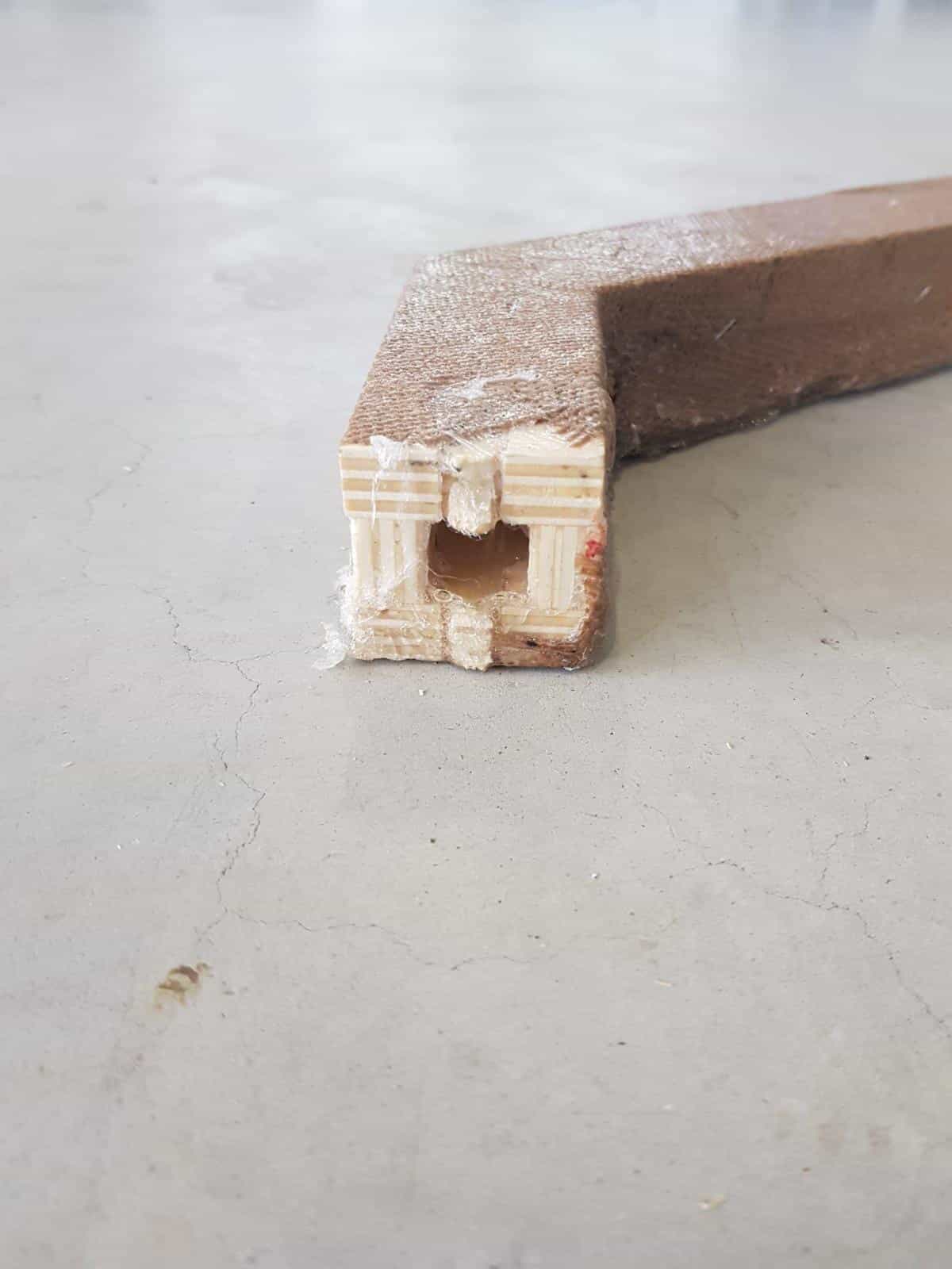
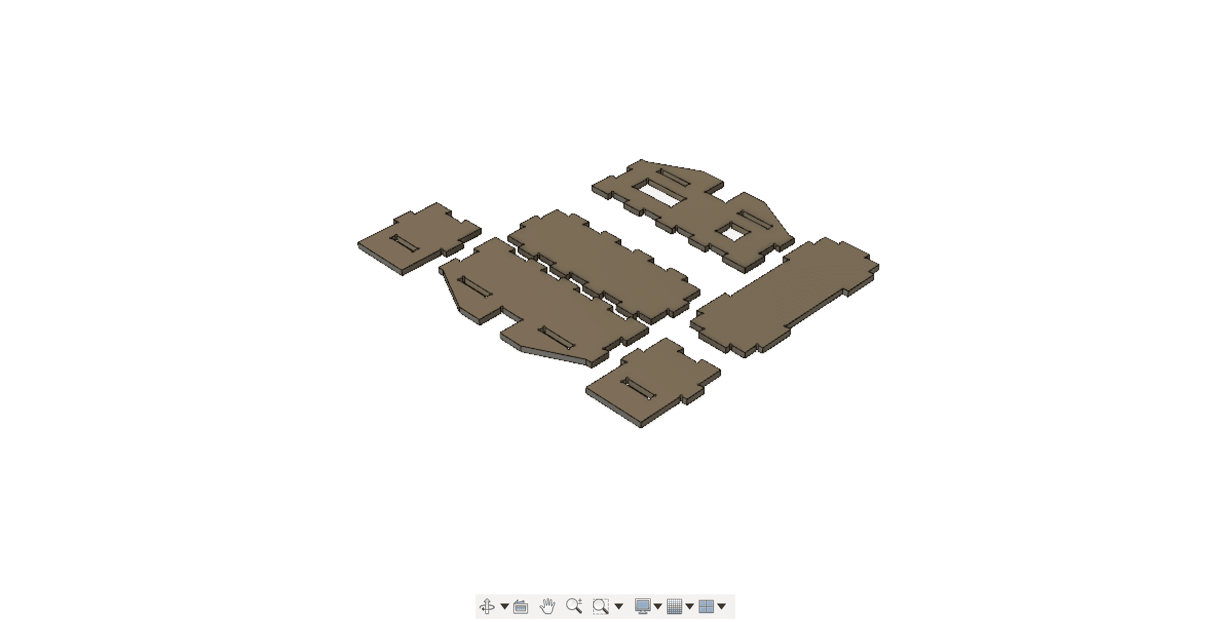
I started off with designing a frame in fusion360, if you would like to have a introduction to fusion please visit my week3 documentation. We needed a light but also robust frame for the kart since we use brushless motors every kg could make a significant difference. So I decided to make a pressfit beam design using very light but also weak 12mm plywood. I started sketching and modeling possible ways to do beams that have a small diameter and at the end I was able to produce a test piece using fusion.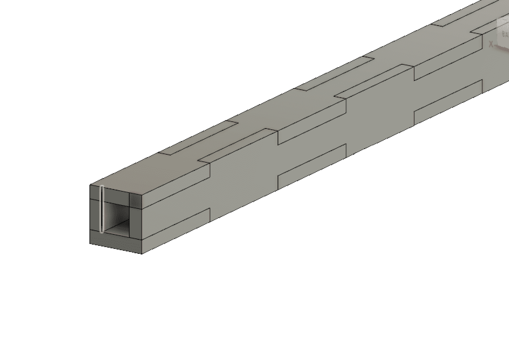
the construction came out to be quite strong but also very light, but it was still not able to carry over 100kg of weight. So we decided to coat everything with carbonfiber. Before we started testing to coat wood with carbonfiber, we tried to use juta and and epoxy.
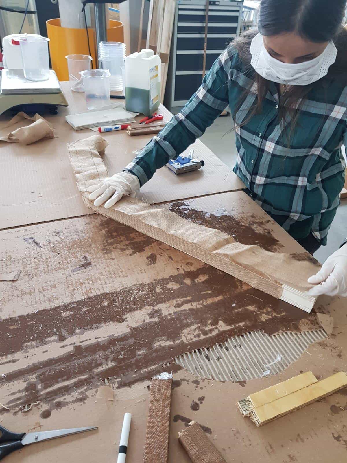
To our suprise it came out very strong and was exactly what we wanted to archieve by using carbonfiber. Because of the costs we then decided to go on with juta instead of carobnfiber.
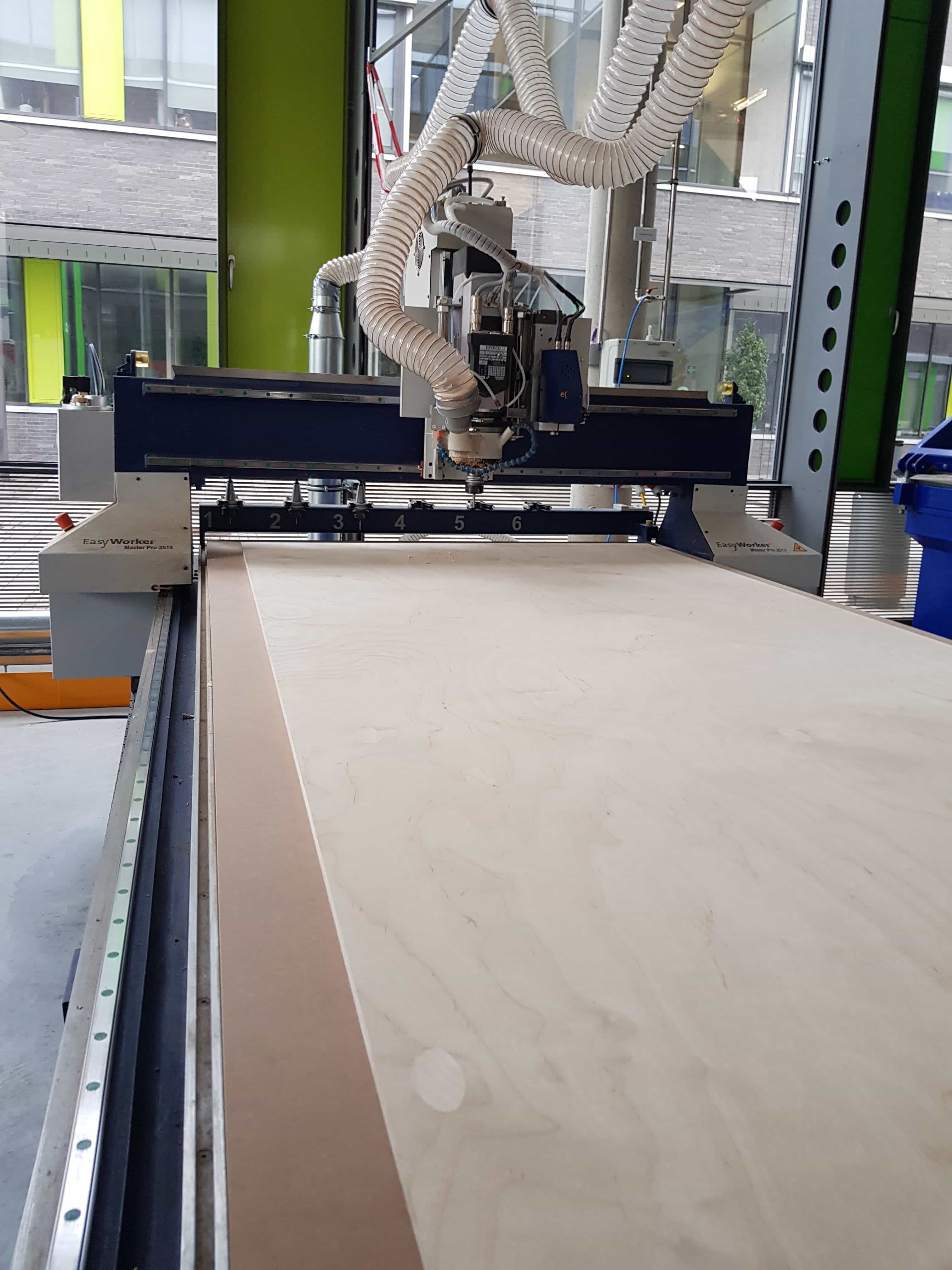
After we have finished our tests I was able to go on with the design of the frame. We decide to cut the upper and the bottom plane out of one piece to give it more stability.
YOUTUBE LINK
I used the cnc machine to mill the frame and its parts out of plywood, it took about 3 hours to cut out everything
Then we have assembled all the parts together, which was the first milestone we have reached when builing the kart.
YOUTUBE LINK
GAS PEDAL
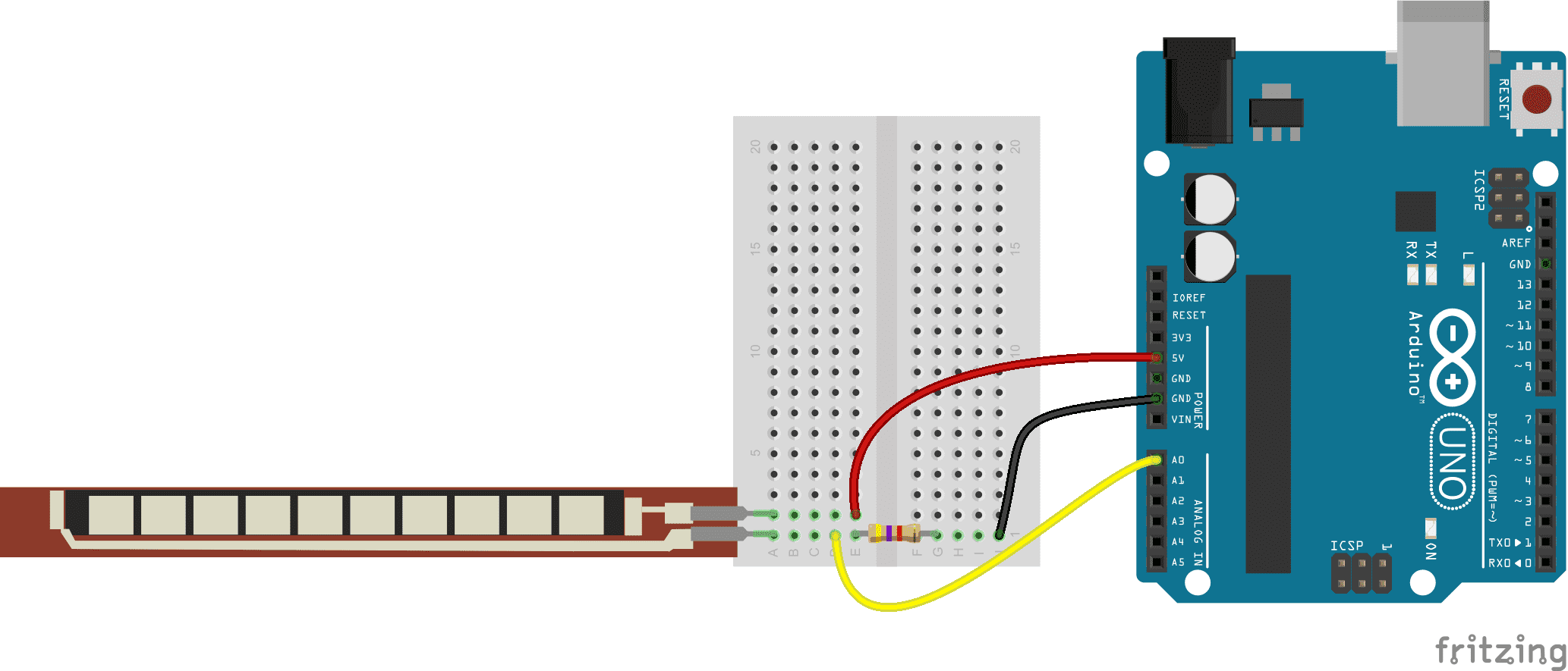
Since we were building a gokart we needed also a gas pedal to speed up the gokart. Instead of using a usual button or switch. I decided to use a flexing sensor, which I will attach to a pedal also milled out of wood. I have used a atmega 328p chip on my designed board so I followed this schematik.
the code I have used to control the motors with the flex sensor is as following
#include


bool auth;
int value=70;													//create a random value
const int flexPin = A0;											//set analog pin of flex sensor
const int motor=10;												//set motor pin
void setup() {


  Serial.begin(115200);
  pinMode(motor,OUTPUT);
}

void loop() {


  value = analogRead(flexPin);									//read value of flex sensor

  value = map(value, 150, 254, 300, 150);						//map value of flex sensor from 150 to 300

  gas();
  }

}


void gas(){
  analogWrite(motor, value);
  }
To have more grip onto the pedal I used the lasercutter to engrave a pattern into the wood that will give more grip.
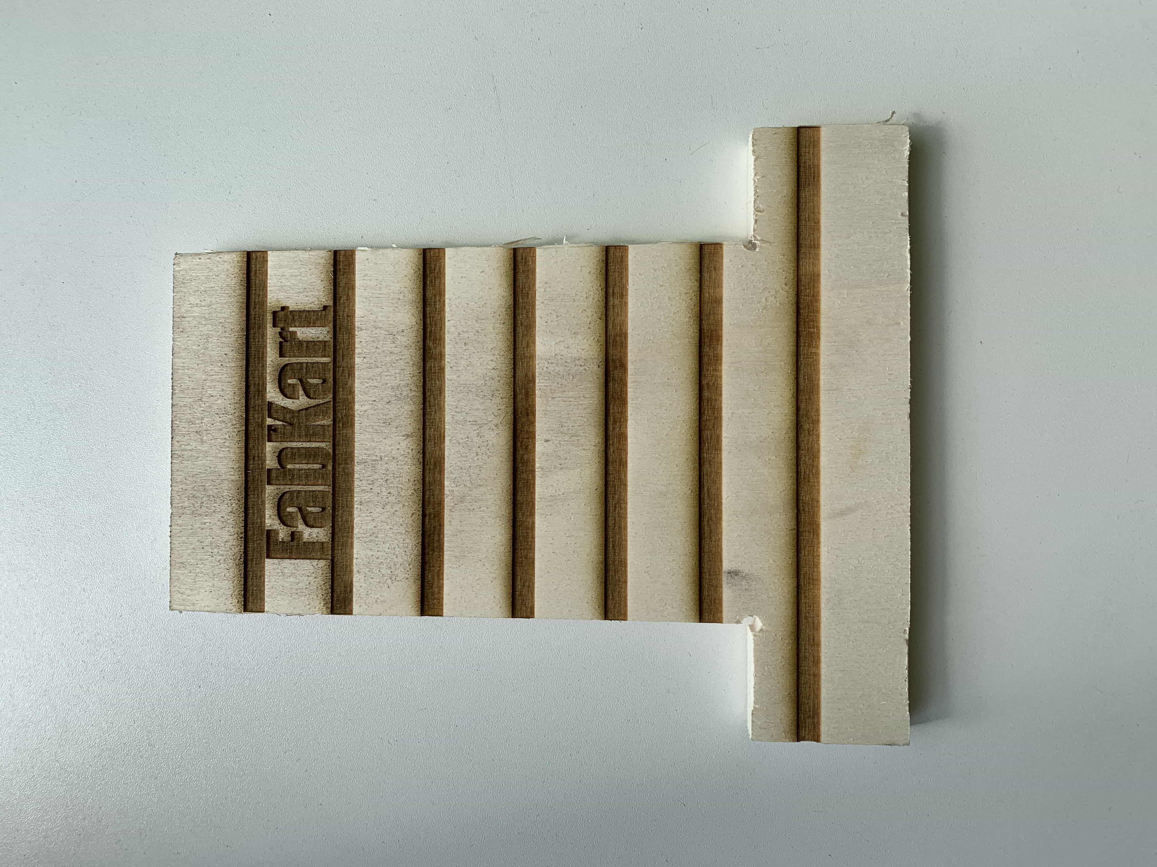
The only problem was, that attaching the flex sensor to the pedal without any case would have been a risk because the flex sensor is very weak against any weather condition and force applied to it. So I designed a very thin case for the flex sensor.
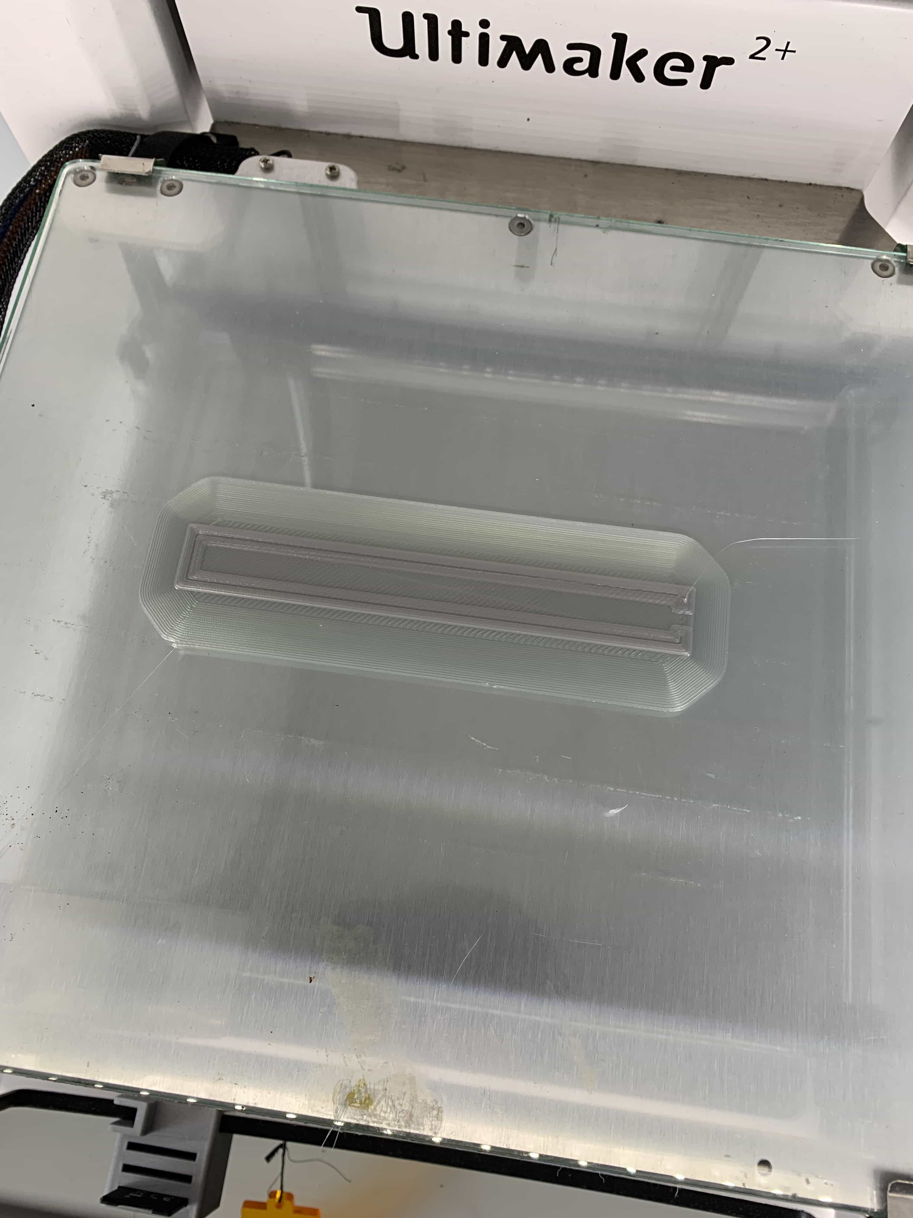
But just printing the case out of play wouldnt have worked, so I printed the case out of flexible pla. To get the sensor into the housing I started the print properly and when it was about to print the top layer I paused the print and placed the sensor into the not yet finished print. I pressed resume and the printer printed the top layer, so that the flex sensor was closed into the case.
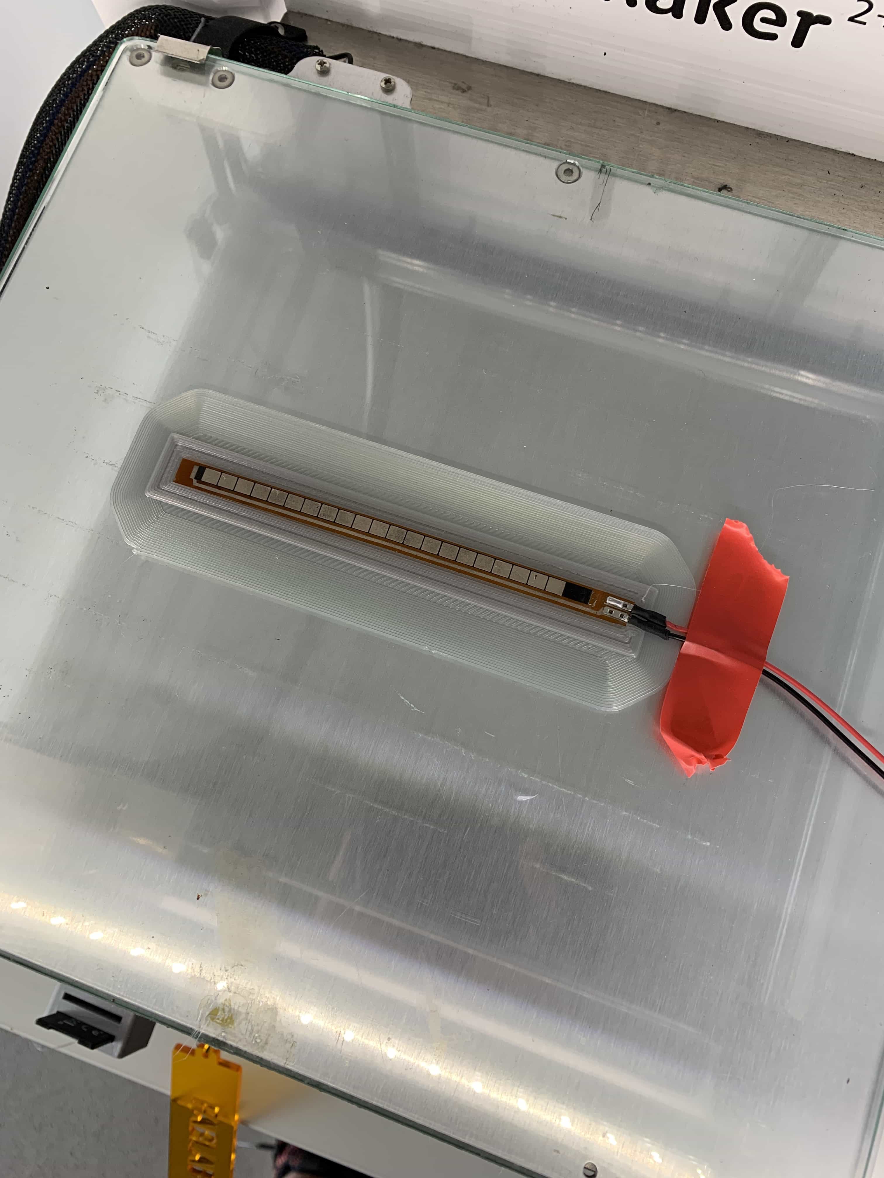
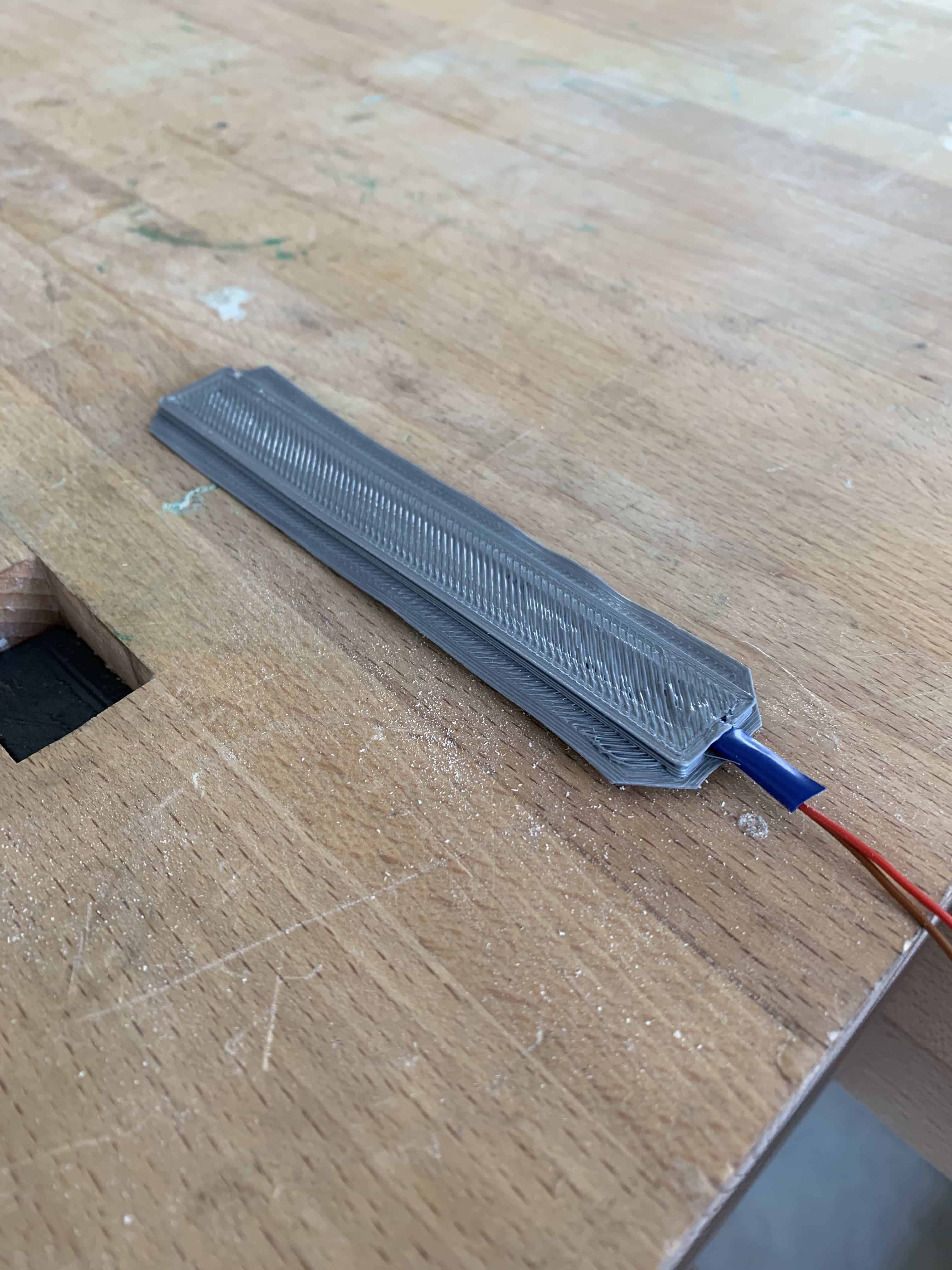
The case for the sensor came out perfectly to fit
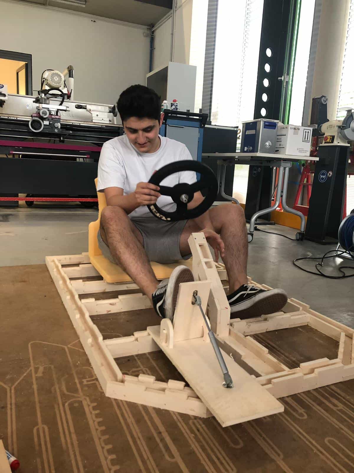
For the next step I had to design pedals, the plan was to attach the pedal to a small piston which will push the pedal back to its starting position, just like in a gokart. So I designed the pedal in fusion..
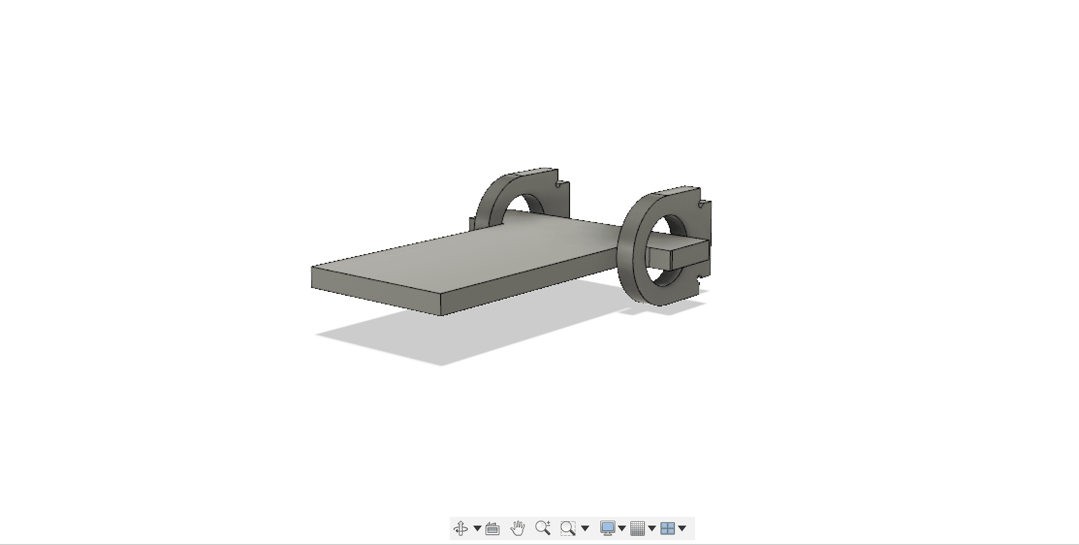
and attached the piston to it, so I was able to put it onto the frame and test it.
YOUTUBE LINK
AUTHENTICATION & DISPLAY
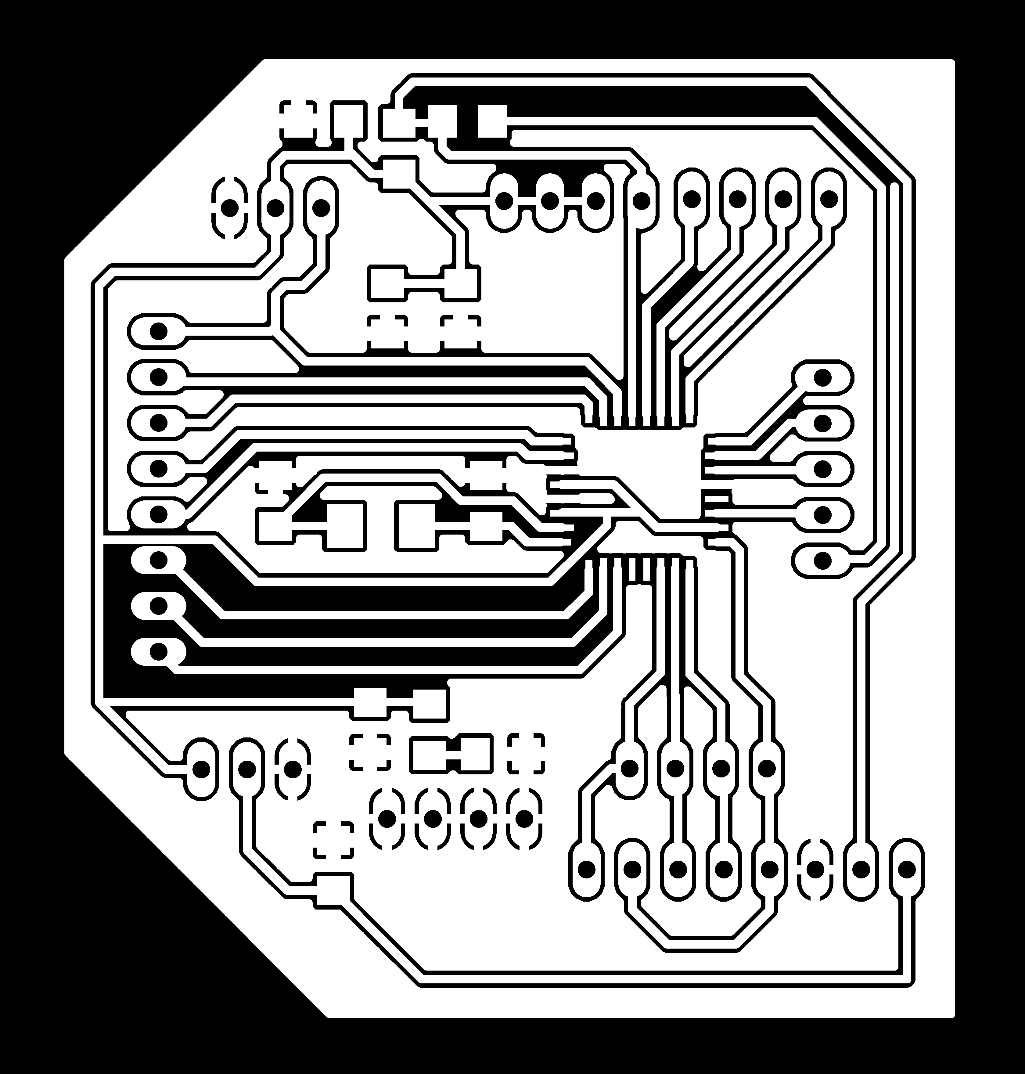
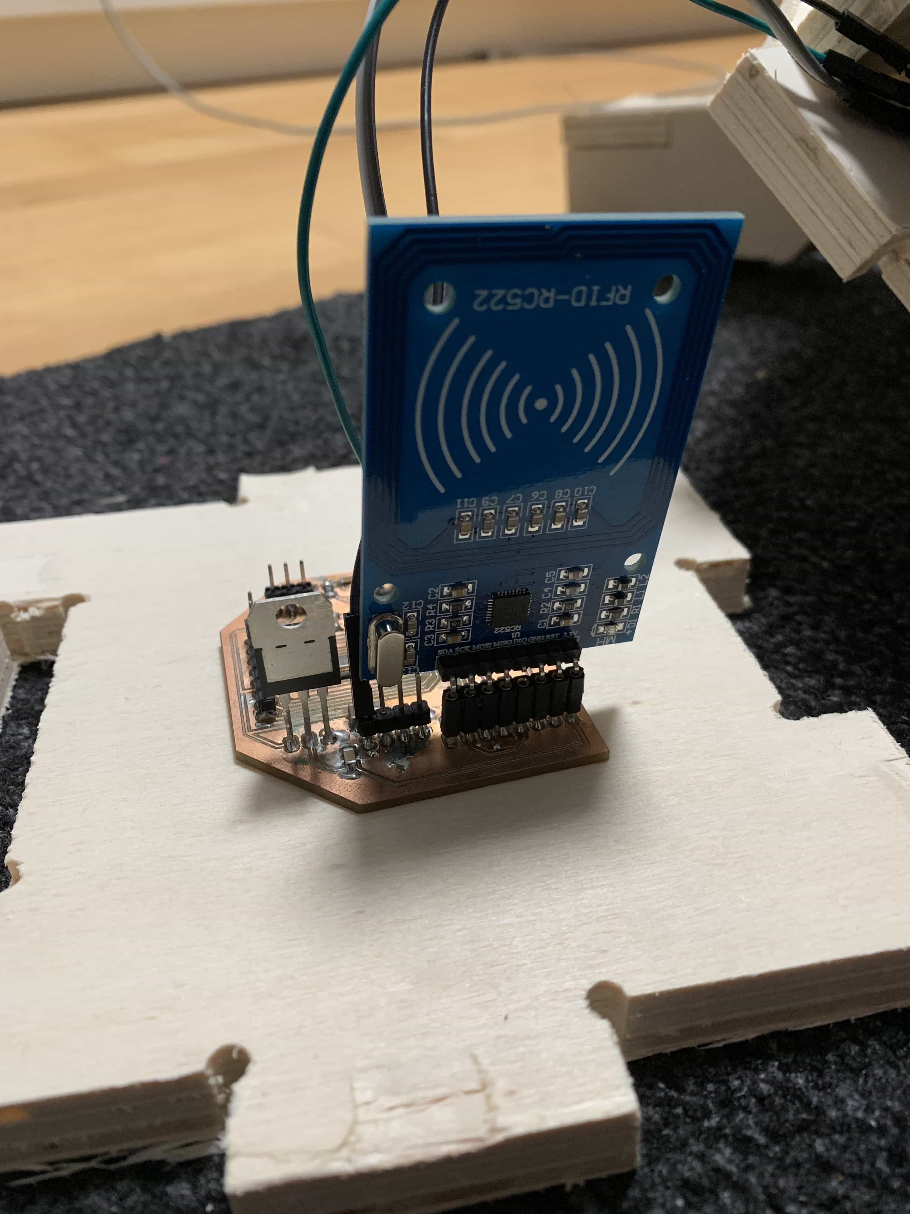
I thought it would be unique if the kart would have some kind of car key system, some sort of authentication so that only the owner of the key could drive the kart. I came to the idea to use an rfid scanner to authenticate myself to the kart. I described the whole authentication in my input devices assignment. The plan was that the card would not drive until I hold my rfid chip to the scanner. I started by designing a board to use with the rfid scanner based on an atmega 328p chipset.
the code of the rfid scanner follows a simple comparision. It will scan every rfid chip and if the chip has the same id as the master chip the authentication is completed
	#include
#include
#include
#include
Servo myservo;
bool auth=false;
constexpr uint8_t RST_PIN = 9;     // Configurable, see typical pin layout above
constexpr uint8_t SS_PIN = 10;     // Configurable, see typical pin layout above

MFRC522 rfid(SS_PIN, RST_PIN); // Instance of the class

MFRC522::MIFARE_Key key;

// Init array that will store new NUID
byte nuidPICC[4];


void setup() {
  Wire.begin();

  Serial.begin(115200);

  SPI.begin(); // Init SPI bus
  rfid.PCD_Init(); // Init MFRC522

  for (byte i = 0; i < 6; i++) {
    key.keyByte[i] = 0xFF;
  }


}

void loop() {

  // Look for new cards
  if ( ! rfid.PICC_IsNewCardPresent())

    return;

  // Verify if the NUID has been readed
  if ( ! rfid.PICC_ReadCardSerial())
    return;

 // Serial.print(F("PICC type: "));
  MFRC522::PICC_Type piccType = rfid.PICC_GetType(rfid.uid.sak);
  //Serial.println(rfid.PICC_GetTypeName(piccType));

  // Check is the PICC of Classic MIFARE type
  if (piccType != MFRC522::PICC_TYPE_MIFARE_MINI &&
    piccType != MFRC522::PICC_TYPE_MIFARE_1K &&
    piccType != MFRC522::PICC_TYPE_MIFARE_4K) {
    //Serial.println(F("Your tag is not of type MIFARE Classic."));
    return;
  }
  //Check if the scanned tag has the same NUID by comparing the array with the actual numbers
  if (rfid.uid.uidByte[0] == 201 &&
    rfid.uid.uidByte[1] == 211 &&
    rfid.uid.uidByte[2] == 124 &&
    rfid.uid.uidByte[3] == 91 ) {
 //print hello message
  if(auth==false){
  auth=true;
  Wire.beginTransmission(11);
  Wire.write(true);
  Wire.endTransmission();

    Serial.println(F("Hello Master!"));
  }else if(auth==true){
    Wire.beginTransmission(11);
  auth=false;
  Wire.write(false);
  Wire.endTransmission();
    }
    // Store NUID into nuidPICC array
    for (byte i = 0; i < 4; i++) {
      nuidPICC[i] = rfid.uid.uidByte[i];
    }


  }


//Check if the scanned tag has the same NUID by comparing the array with the actual numbers
 else if (rfid.uid.uidByte[0] == 36 &&
    rfid.uid.uidByte[1] == 159 &&
    rfid.uid.uidByte[2] == 223 &&
    rfid.uid.uidByte[3] == 43 ) {

//Print hello message
   if(auth==false){
  Wire.beginTransmission(11);
  auth=true;
  Wire.write(true);
  Wire.endTransmission();

    Serial.println(F("Hello Mr.Rustamov!"));
  }
  else if(auth==true){
    Wire.beginTransmission(11);
  auth=false;
  Wire.write(false);
  Wire.endTransmission();
    }


    // Store NUID into nuidPICC array
    for (byte i = 0; i < 4; i++) {
      nuidPICC[i] = rfid.uid.uidByte[i];
    }


  }
///Check if scanned tag has a difference to the master tags
  else if (rfid.uid.uidByte[0] != 201 ||
    rfid.uid.uidByte[0] != 36 ||
    rfid.uid.uidByte[1] != 211 ||
    rfid.uid.uidByte[1] != 159 ||
    rfid.uid.uidByte[2] != 124 ||
    rfid.uid.uidByte[2] != 223 ||
    rfid.uid.uidByte[3] != 91 ||
    rfid.uid.uidByte[3] != 43
                                  ) {

    Wire.beginTransmission(11);
  Wire.write(false);
  auth=false;
  Wire.endTransmission();
    // Store NUID into nuidPICC array
    for (byte i = 0; i < 4; i++) {
      nuidPICC[i] = rfid.uid.uidByte[i];
    }


    //Giving an error message because the tag is not a master tag
    Serial.println(F("Invalid Card!"));
    }
  //Scanning a new tag
  if (rfid.uid.uidByte[0] != nuidPICC[0] ||
    rfid.uid.uidByte[1] != nuidPICC[1] ||
    rfid.uid.uidByte[2] != nuidPICC[2] ||
    rfid.uid.uidByte[3] != nuidPICC[3] ) {

    Serial.write(false);
    // Store NUID into nuidPICC array
    for (byte i = 0; i < 4; i++) {
      nuidPICC[i] = rfid.uid.uidByte[i];
    }
    }
  // Halt PICC
  rfid.PICC_HaltA();

  // Stop encryption on PCD
  rfid.PCD_StopCrypto1();
}


/**
 * Helper routine to dump a byte array as hex values to Serial.
 */
void printHex(byte *buffer, byte bufferSize) {
  for (byte i = 0; i < bufferSize; i++) {
    Serial.print(buffer[i] < 0x10 ? " 0" : " ");
    Serial.print(buffer[i], HEX);
  }
}

/**
 * Helper routine to dump a byte array as dec values to Serial.
 */
void printDec(byte *buffer, byte bufferSize) {
  for (byte i = 0; i < bufferSize; i++) {
    Serial.print(buffer[i] < 0x10 ? " 0" : " ");
    Serial.print(buffer[i], DEC);
  }
}
The information will then be send to another board over I2C communication. To make sure that the user has some kind of feedback from the authentication, I attached a display which will show the progress of authentication following my output device assignmentshows in detail how the display works. To combine the scanner and the display I wrote a simple code using the rfid board as a master and the other board which my partner alessa produced to run the motors as a slave that will receive all the information.
	#include                                      //required to use lcd
#include

const int rs = 12, en = 11, d4 = 5, d5 = 4, d6 = 3, d7 = 2;   //setting the pins
LiquidCrystal lcd(rs, en, d4, d5, d6, d7);                    //setting display up
bool auth;
int value=70;
const int flexPin = A0;
const int motor=10;
void setup() {
  lcd.begin(20,4);                                            //begin display with size (lenghtxheight)
  Wire.begin(11);                                             //begin wire on port 11
  Wire.onReceive(receiveEvent);                               //when data available trigger receiveEvent
  // put your setup code here, to run once:


  Serial.begin(115200);
  pinMode(motor,OUTPUT);
}

void loop() {
  //delay(100);

  value = analogRead(flexPin);                                  //analog read the flex sensor

  value = map(value, 150, 254, 300, 150);
  if(auth == true){                                             //when succesfully authenticated the gas() function can be called
    Serial.println("Successfully Authenticated!");
    lcd.setCursor(2,0);                                        //cursor on the second pixel of first line
    lcd.print("Successfully  ");                                 //display string
    lcd.setCursor(2,1);                                        //cursor on the fourth pixel of second line
    lcd.print("Authenticated!");                               //dsiplay string


    gas();                                                      //gas function to drive the motor
  }
  else if(auth == false){
    Serial.println("Authentication required!");                //do the same thing again to replace the first lcd print
    lcd.setCursor(2,0);
    lcd.print("Authentication");
    lcd.setCursor(2,1);
    lcd.print("required!     ");

    }
}

void receiveEvent() {
  while (0 < Wire.available()) {                                //while any information is available
    auth = Wire.read();                                         //store the information in bool "auth"
  }
  Serial.println(auth);

  //Serial.println(value);
  // put your main code here, to run repeatedly:

}

void gas(){
  analogWrite(motor, value);                                    //motor driving function
  }
So I have used input and output devices, also electronics design and production, but I wanted to join them all together in one place. I designed a simple dashboard that will be attached behind the steering wheel, so it can hold the rfid scanner and the display in front of the driver
Finally the whole authentication experience was like this.
ATTACHING THE WHEELS
I created a 3dmodel of a wheel attachment in a zylinder form.
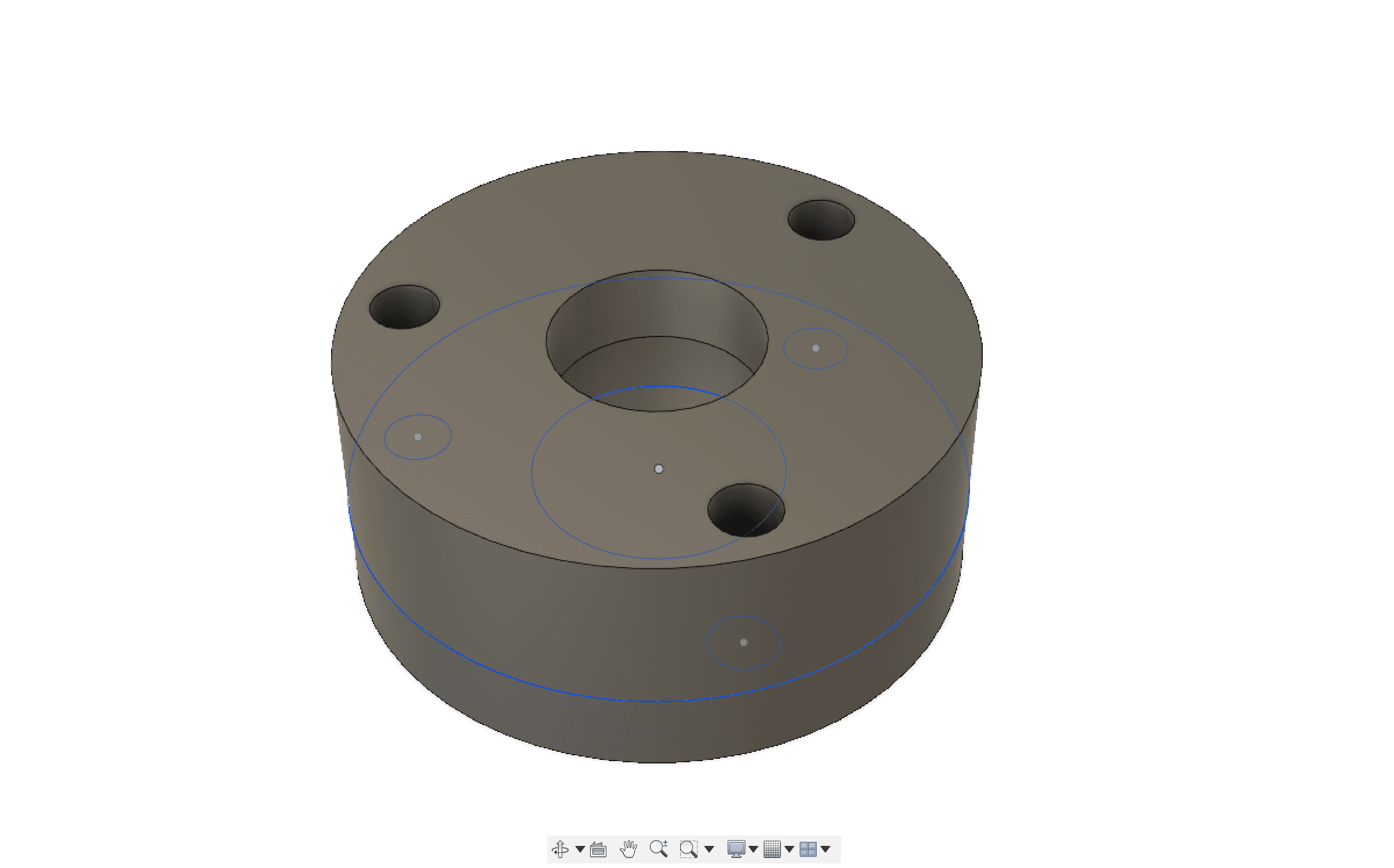
Then I used 3d milling to create the wheel attachment out of plum
YOUTUBE LINK
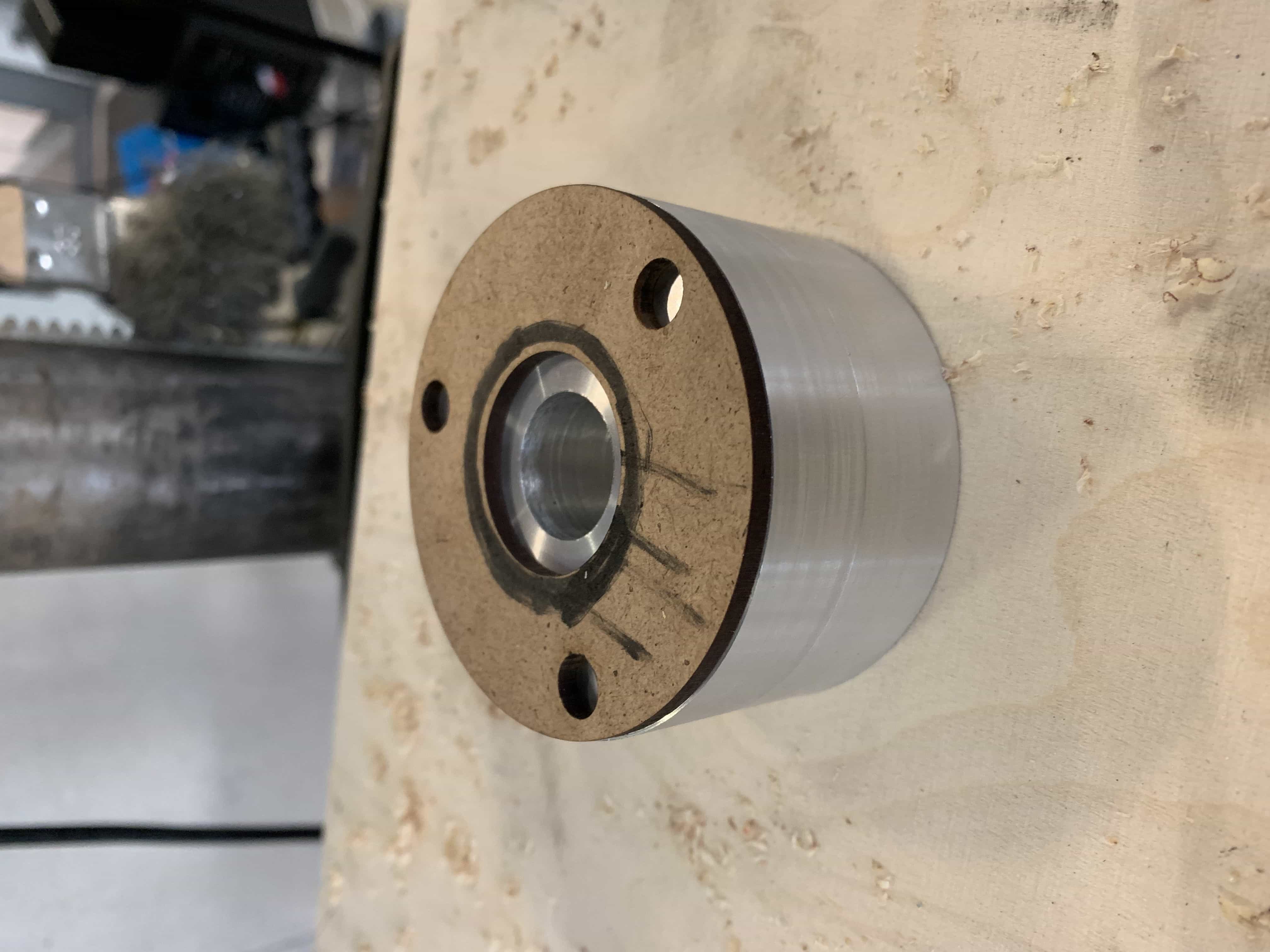
But unfortenatly it wasn't as we expected it to be and we were worrier that the plum could melt under the high amount of friction so we created all the attachment parts out of aluminium using the lathe and used the created models out of plum for testing purposes only.
the parts are mostly used to attach the wheels to the steel rods. I created a template using the laser cutter to allign the holes of the wheels onto the aluminium part.
also we have created a few parts to attach the gears to the rod
YOUTUBE LINKS
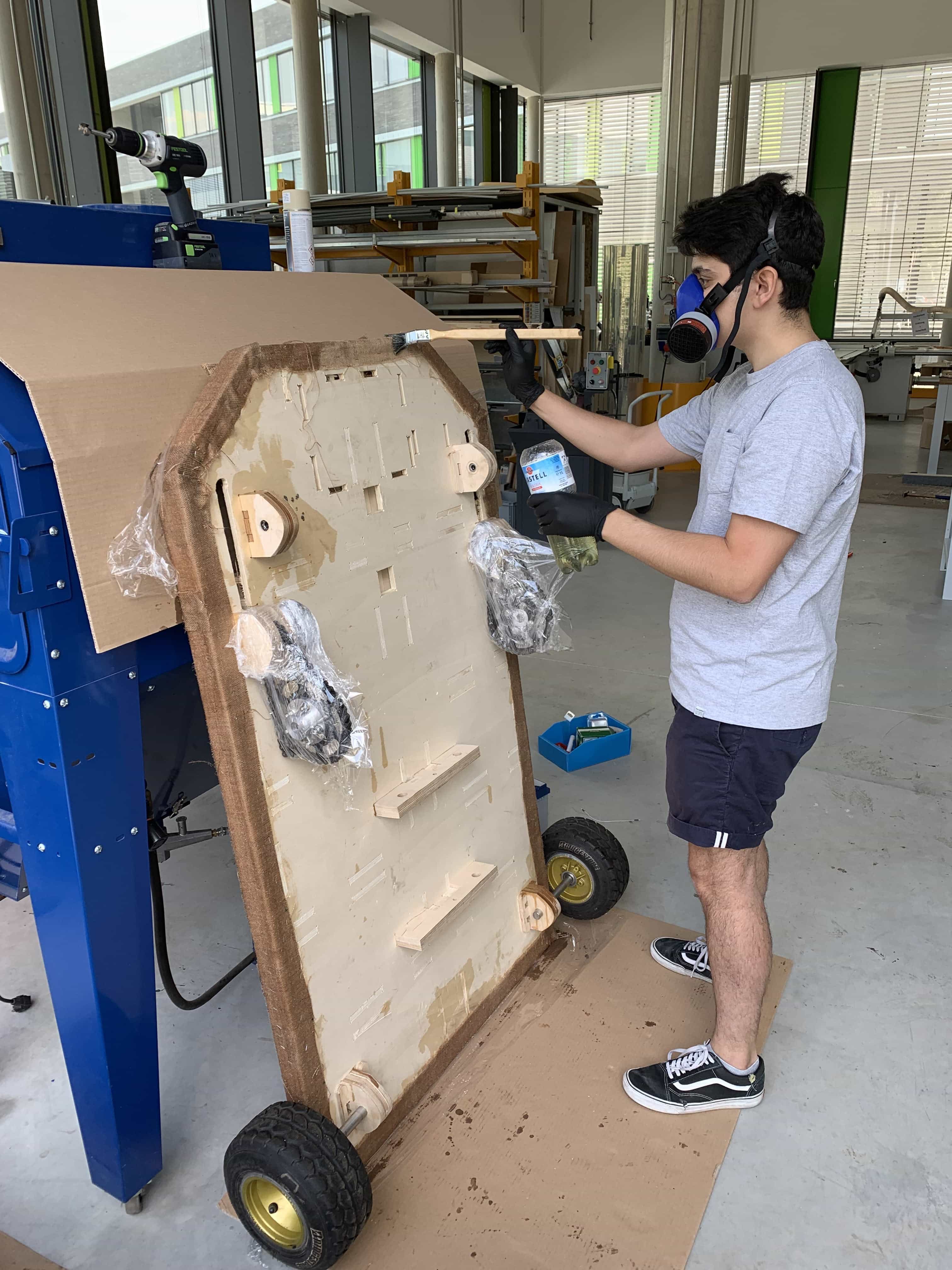
COVERING WITH JUTA
After our tests in the beginning it was clear that we will have to cover the whole frame with juta and epoxy. The plywood on its own was, after our calculations to weak to carry the weight of round about 140kg's. When we assembled the frame our concernes came true and the frame was touching the floor because it was bending a lot. So we covered the frame with juta.
Ater the juta was cured more or less the kart was still flexible but harder and wouldn't touch the floor when standing on it. We did a few tests to make sure that it could handle some weight.
YOUTUBE LINK
Parts like for example the steering wheel or the chair were made of my partner Alessandra Crotty, we have joined together to do this project. Go and check her documentation also following this link.
The current status of the kart is, that we have assembled all the parts and making the kart ready to drive. The absolute time for the epoxy to harden is 7 days so we want to wait until we can test the kart, because anything else would be to risky.
STATUS UPDATE
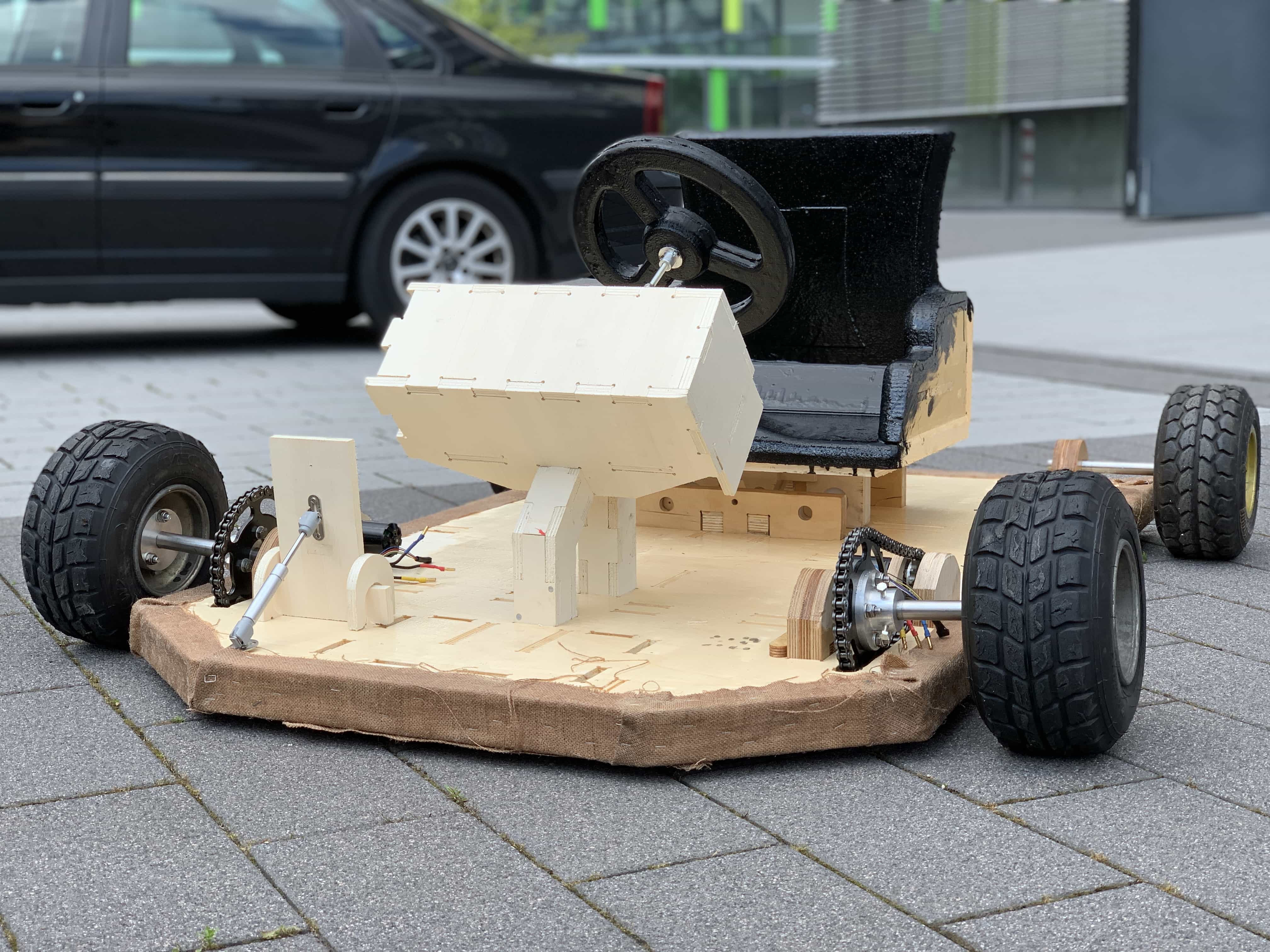
Unfirotenatly we did not get the kart on the streets to drive, due to missing esc controllers that we could not afford. We have tested a lot of ways to power the kart but at the end the sad truth is that proper motors and esc controllers cost quite a bit and you really get what you pay for. We assembled the kart:
I was also able to drive the kart using one motor only, but at this part of course the steering etc was not included, because I only had one motor.
YOUTUBE LINK
The kart finally looks pretty awesome and our plan of a completely wooden kart is a full success.
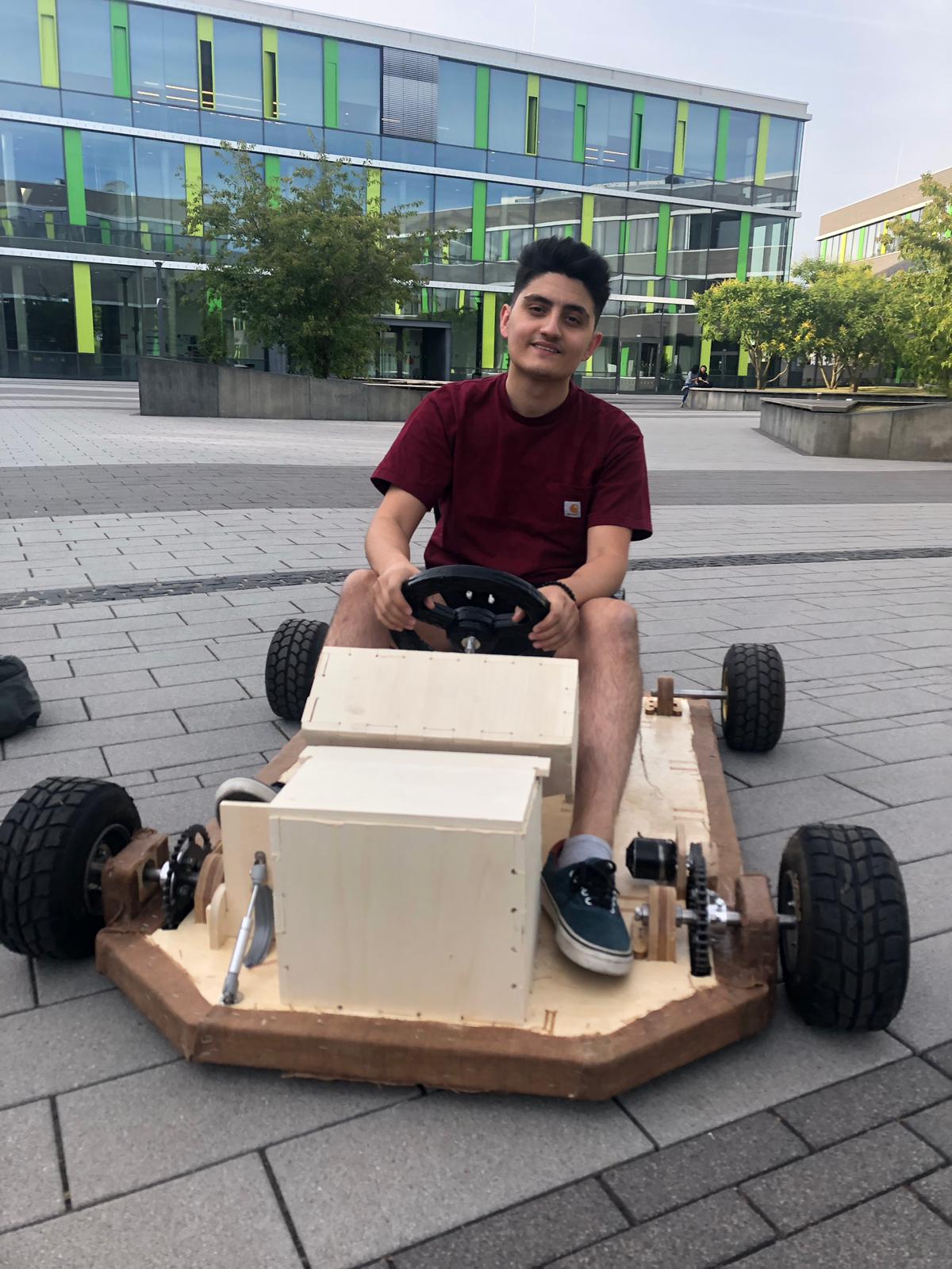
At the end we get to test every single function of the kart including the authentication, the steering, the gas pedal, the display, the frame, the seat. In the following video, we will show the whole process of authentication, driving and steering.