Assignment Overview
Group assignment: - Design a machine that includes mechanism+actuation+automation+application
- Build the mechanical parts and operate it manually
- Document the group project and your individual contribution
Group link
In this assignment we were working on the development of the robot arm for the group.
For machine design, we built a 5-axis robotic arm which will be controlled using web interface control panel.
Other team members handled the mechanical structure and electronics, I was in charge of writing the firmware and developing the interface to control the robot.
Mechanical Design Principles
Kinematics
Study of motion without considering forces - position, velocity, and acceleration
Dynamics
Analysis of forces and torques that cause motion in mechanical systems
Mechanisms
Linkages, gears, cams, and other mechanical elements that transmit motion
Mechanical Project
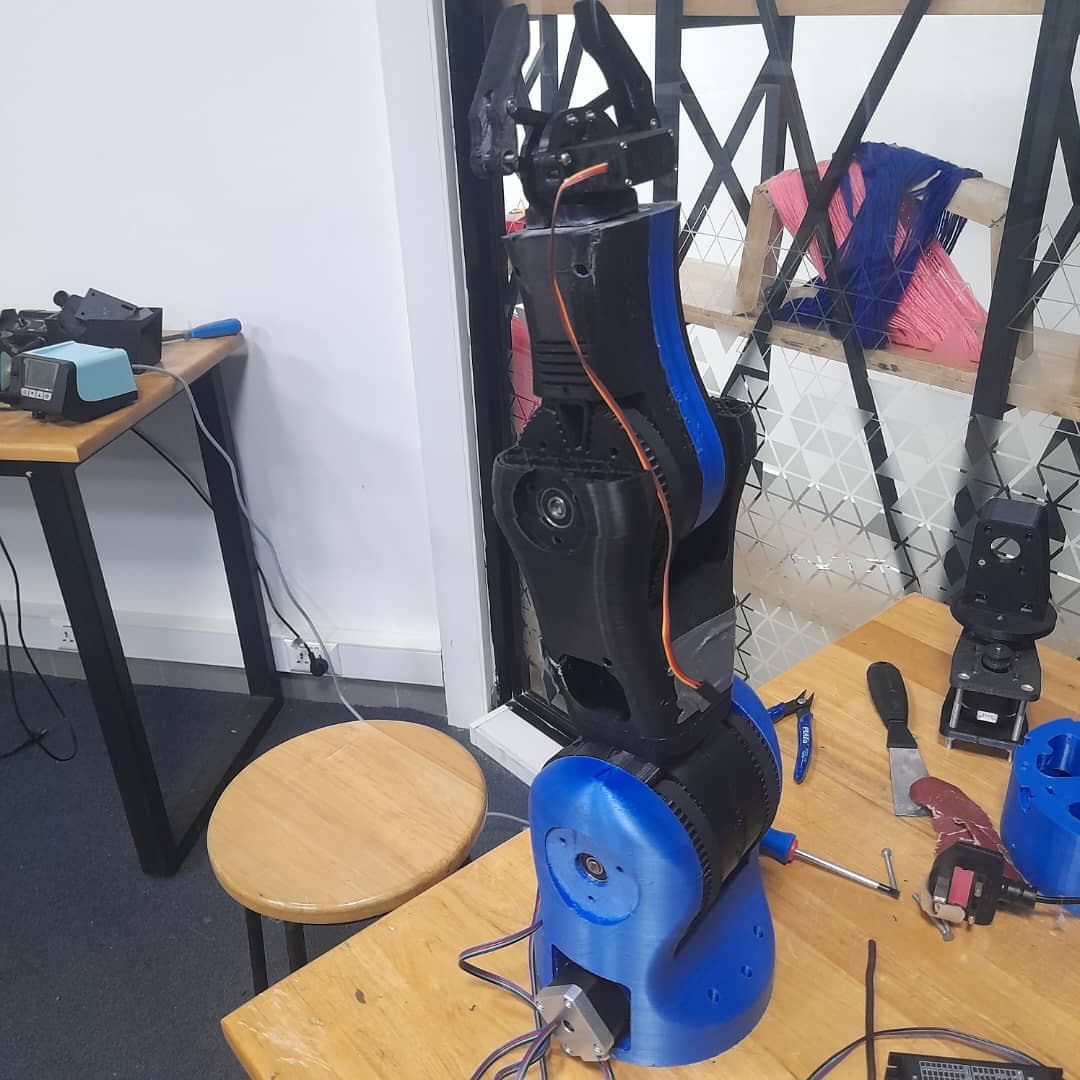
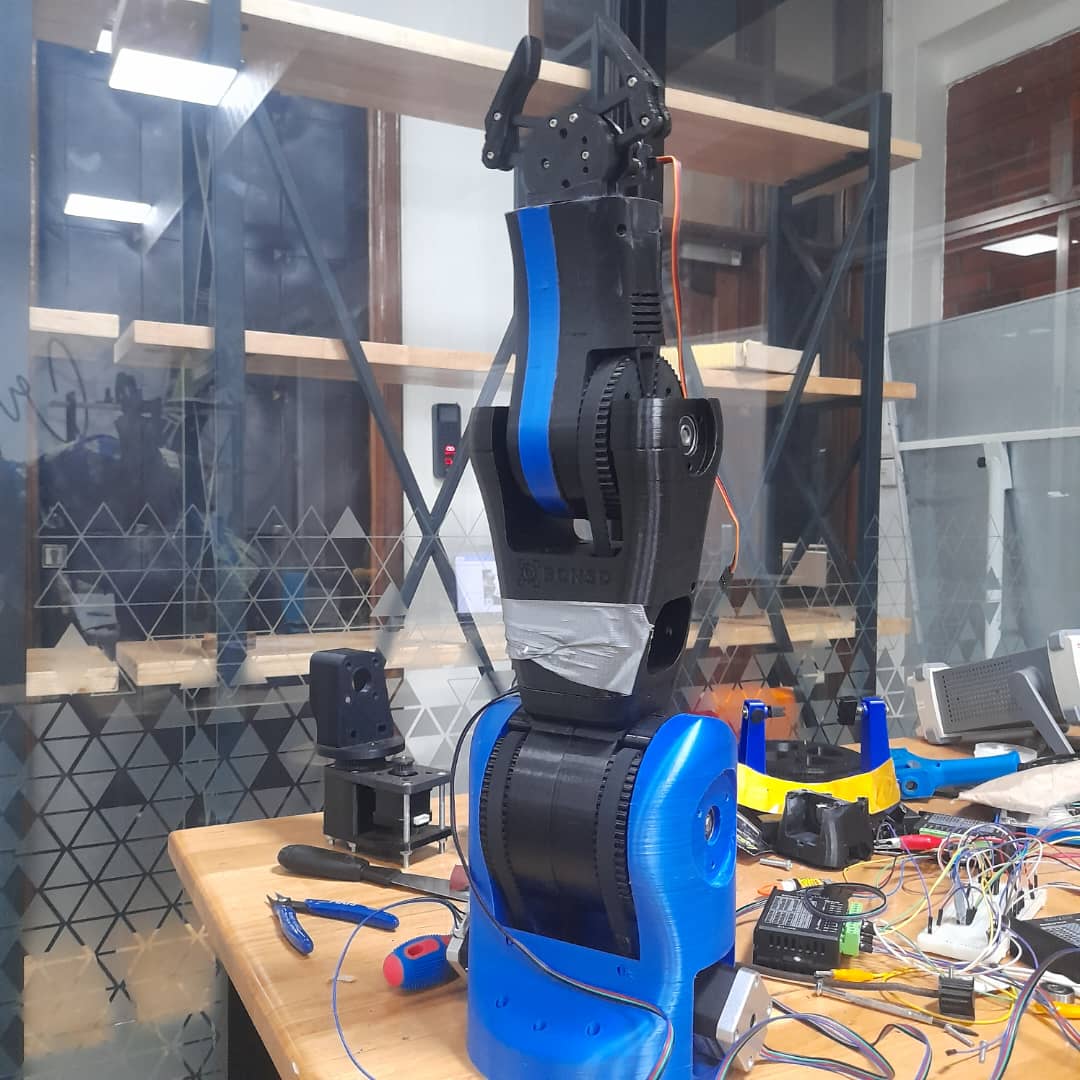
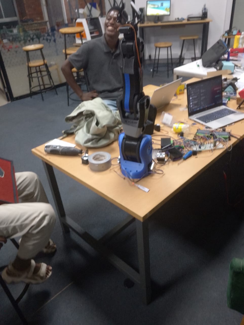
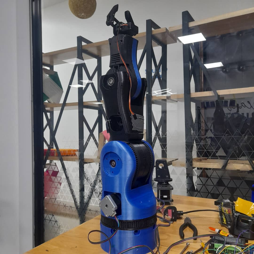
Pick and place Robot arm
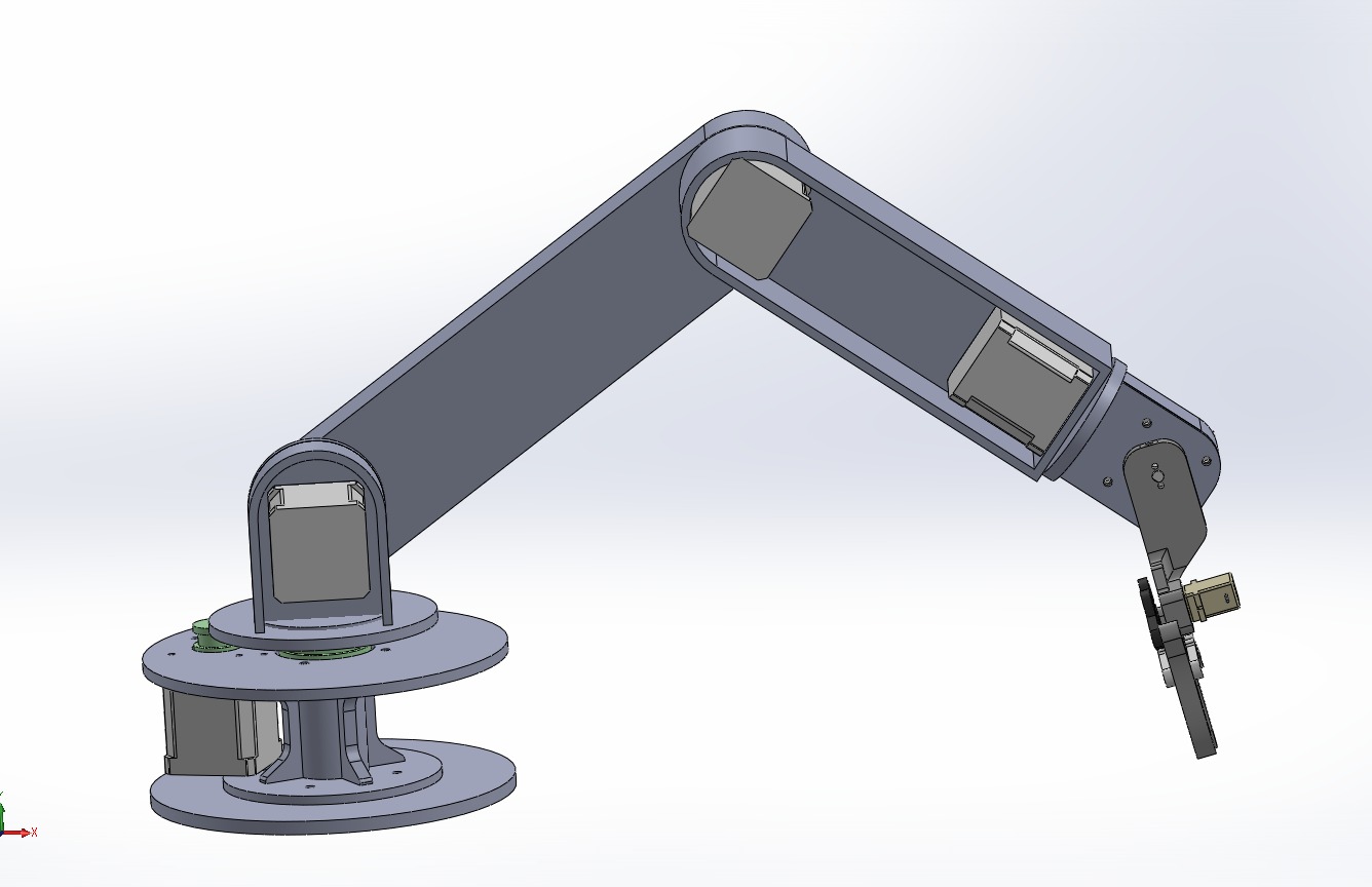
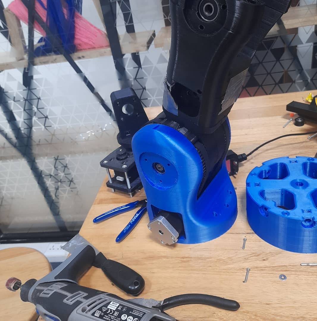
- Assisted in assembling robotic arm joints: base, shoulder, elbow, wrist, and gripper.
- Mounted motors and ensured structural alignment for smooth movement.
- Performed tuning and mechanical tests to verify joint performance.
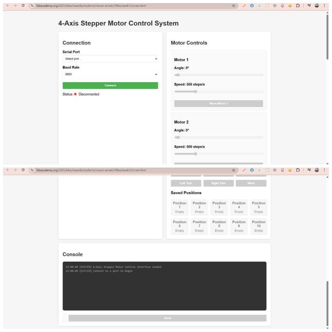
Interface preview
Firmware Code
- Designed a manual control panel using Web serial communication.
- Mapped controls to microcontroller I/O pins for each axis.
- Labeled and tested the interface for usability and responsiveness.
The Core Features we Implemented:
- Multi-axis stepper control via serial interface
- Angle-based motion mapping (0–180°) with step conversion
- Session-based position memory with support for save and playback
- Looped playback feature with adjustable timing between steps
- Motor reset function to bring all motors to 0°
Challenges
- Serial Command Parsing: Since the interface was based on comma-separated strings, splitting and validating inputs reliably was critical to prevent misexecution.
- Angle to Step Conversion: Each motor used a specific number of steps per revolution, requiring custom scaling (e.g., 1° ≈ 5.68 steps for 28BYJ-48 with gear ratio).
- Position Memory: EEPROM was avoided to preserve lifespan, so all positions were stored in volatile memory during runtime and lost on power-off.
- Looped Playback Timing: Introducing a custom delay between motor sequences helped simulate coordinated movement but required precise state tracking.
- Safety Reset: A manual reset command was implemented to avoid mechanical overextension by returning motors to their safe base (0°) position.
-
User Interface (UI) Overview
- Angle Adjustment: Set the desired motor angle using a slider.
- Speed Control: Define movement speed in steps per second.
- Move Command: A dedicated “Move Motor” button for each axis to execute commands.
The 4-Axis Stepper Motor Control System features a streamlined, web-based interface optimized for real-time motor control and precise position management. The interface is intuitive, responsive, and accessible via Wi-Fi, offering comprehensive control over each motor’s angle and speed.
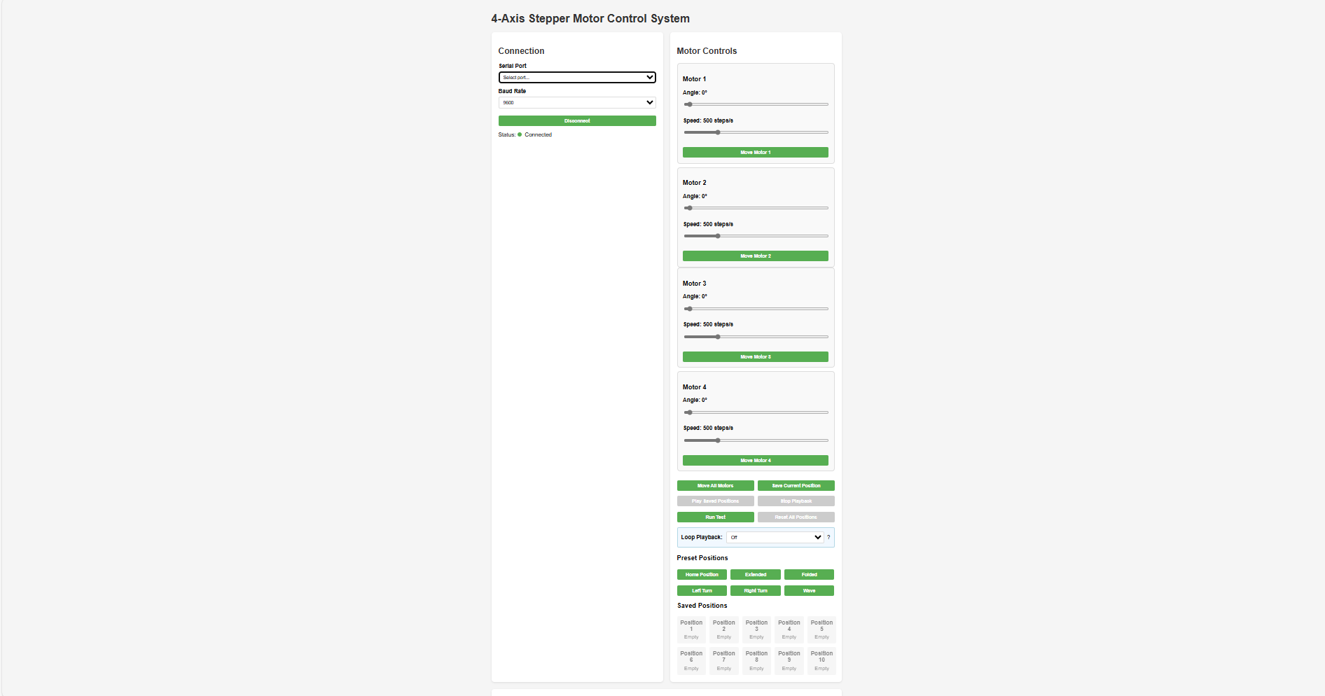
Main UI Sections 1. Connection Panel
Select a serial port and baud rate, then connect. Real-time connection status is shown using clear visual indicators.
2. Motor ControlsEach of the four stepper motors includes:
Quick-save and recall up to 10 preset motor positions. Custom labels such as “Left Turn,” “Right Turn,” and “Wave” help with easy identification and reuse.
4. Console OutputDisplays real-time system feedback, including command logs and status messages for monitoring performance and troubleshooting.
- Worked with the electronics team to wire and test the control panel.
- Participated in debugging and system integration.
What I have learned from this project.
Learning Outcomes 1. Mechanical Design & Fabrication- Learned how to design a multi-joint robotic arm with degrees of freedom for pick-and-place tasks.
- Gained experience in using CAD tools like SolidWorks for 3D modeling and Assembly.
- Developed hands-on skills in digital fabrication (3D printing, assembly).
- Understood mechanical constraints like torque, joint limits, and structural integrity.
- Learned to select suitable motors (stepper and servo) based on torque and precision requirements.
- Gained practical experience with stepper motor drivers.
- Understood the wiring and power requirements of a multi-motor system.
- Explored techniques for managing load and motor heat dissipation.
- Developed skills in embedded programming using Arduino/ESP32.
- Understood how to translate manual operations into automated sequences.
- Learned basic motion planning and joint coordination.
- Experienced how to combine mechanical, electrical, and software components into a working system.
- Understood debugging practices across subsystems mechanical misalignment, electrical faults,load balancing and code errors.
- Gained project management skills: planning, documentation, testing, and iterative improvement.
- Understood how robotic arms are applied in real-life scenarios such as manufacturing and lab automation.
- Reflected on the limitations of the current model and ideated improvements.
- Learned to operate the arm manually and compare its performance with the automated mode.
- Collaborated effectively in a multidisciplinary team by taking ownership of specific components.
- Practiced documenting work clearly for group reports and individual portfolios.