Assignment Overview
Week 19 culminated the Fab Academy program with final project presentations and program completion. This week celebrated the achievements of all assignments and provided an opportunity to share innovations with the global Fab Academy community.
The focus was on effective communication of technical achievements, peer learning, and reflection on the transformative journey through digital fabrication.
My Final Presentation
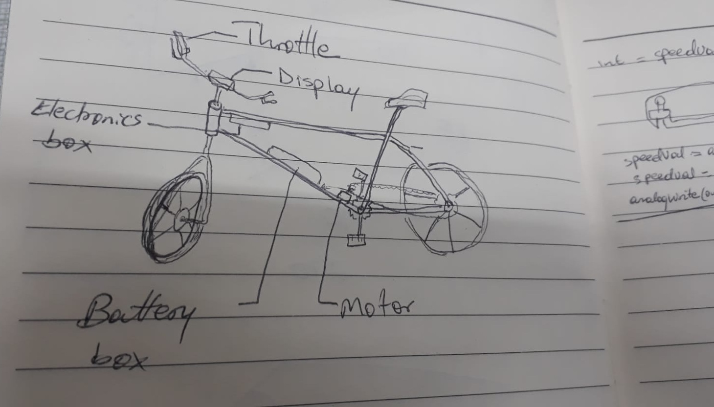
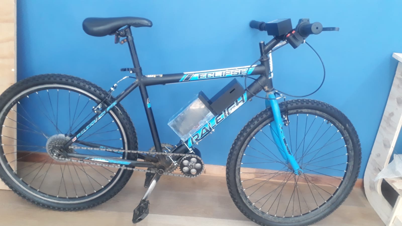
Project demostration-Full bike assembled
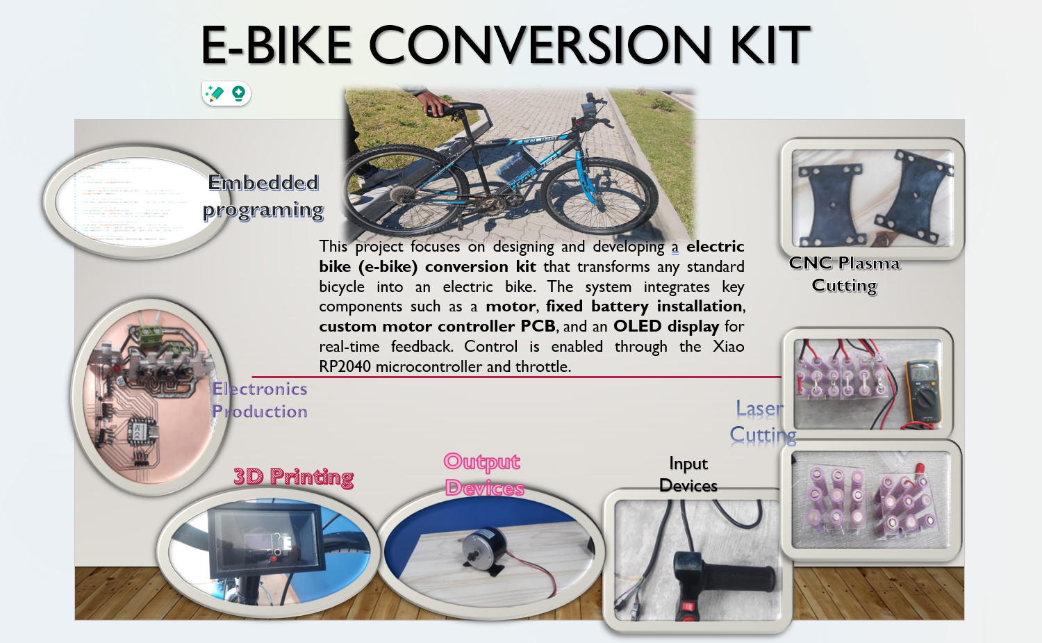
Electric bicycle Conversion Kit
- Document a final project masterpiece that integrates the range of units covered, answering:
- What does it do?
- Who's done what beforehand?
- What did you design?
- What sources did you use?
- What materials and components were used?
- Where did they come from?
- How much did they cost?
- What parts and systems were made?
- What processes were used?
- What questions were answered?
- What worked? What didn't?
- How was it evaluated?
- What are the implications?
The project ecompases the design and production of the conversion kit for bicycle which will be used as a mode of transport to reduce traffic jame and preserving the climate, as it will reduce the carbon footprint from fuel-powered cars.
- Project Overview
• Build a full conversion kit for the motorcycle.
• Design and build circuit board that include voltage regulator for microcontroller and some components that required small voltage.
• Use microcontroller to process throttle input to control the motor speed, and display battery state of charge.
• Display throttle percentage, and fault status on an OLED.
• Enable Bluetooth connectivity for real-time data monitoring via a smartphone app (optional).
• Design 3D-printed display and circuit board enclosure for handlebar mounting.
• Implement fault detection (e.g., MOSFET temperature errors, low battery) on the display.
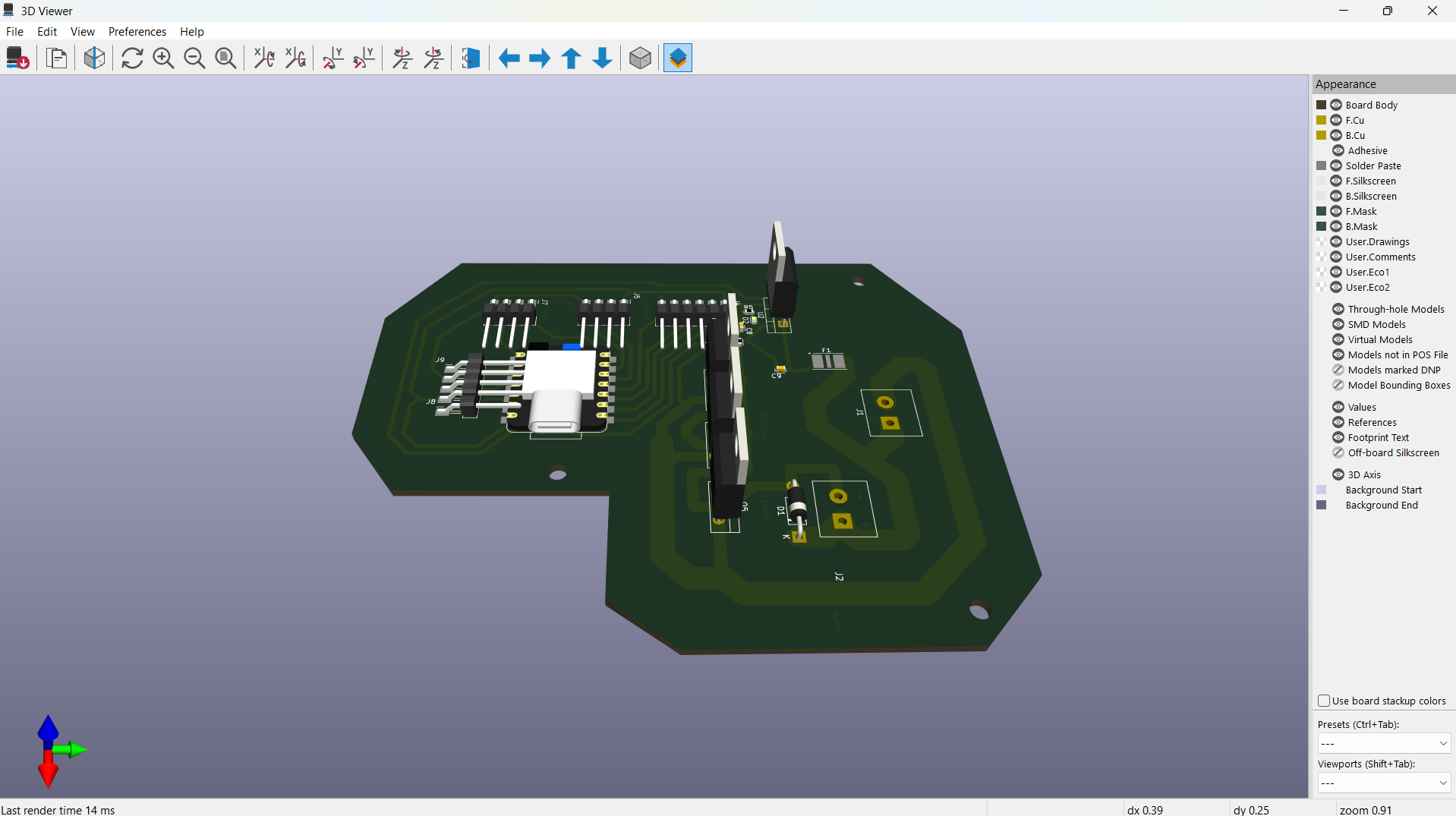
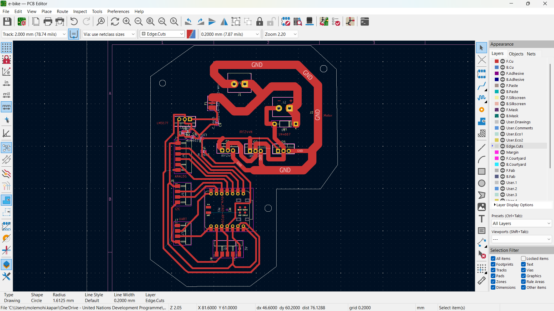
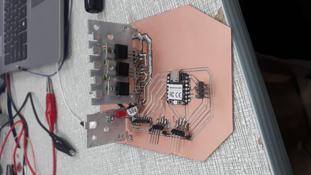
Motor Controller PCB for Final Project Masterpiece
What does It Do?
- Throttle-controlled motor speed
- Overcurrent protection
- Soft start and regenerative braking
- Real-time monitoring via LCD
- 5V output to power microcontroller
- Bafang, Kelly, and VESC offer commercial motor controllers.
- Open-source projects like VESC and SimpleFOC provide firmware and hardware design examples.
- Makers on GitHub and YouTube have built brushed/BLDC motor drivers with Arduino and STM32.
- Custom 1-layer motor controller PCB
- 3D-printed or CNC-cut motor mount and battery enclosure
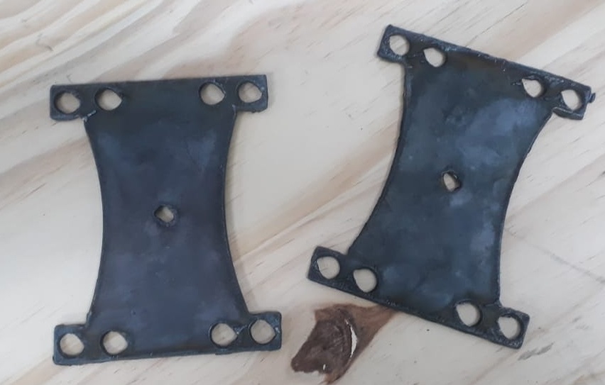
- Motor mount
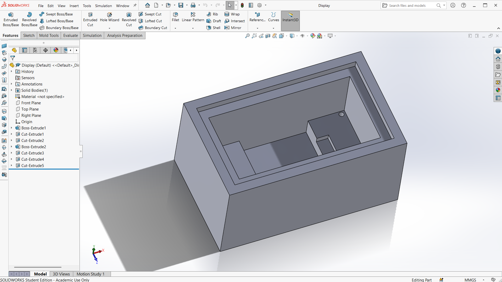
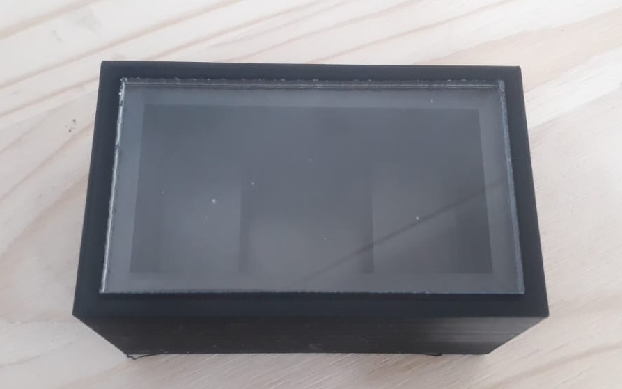
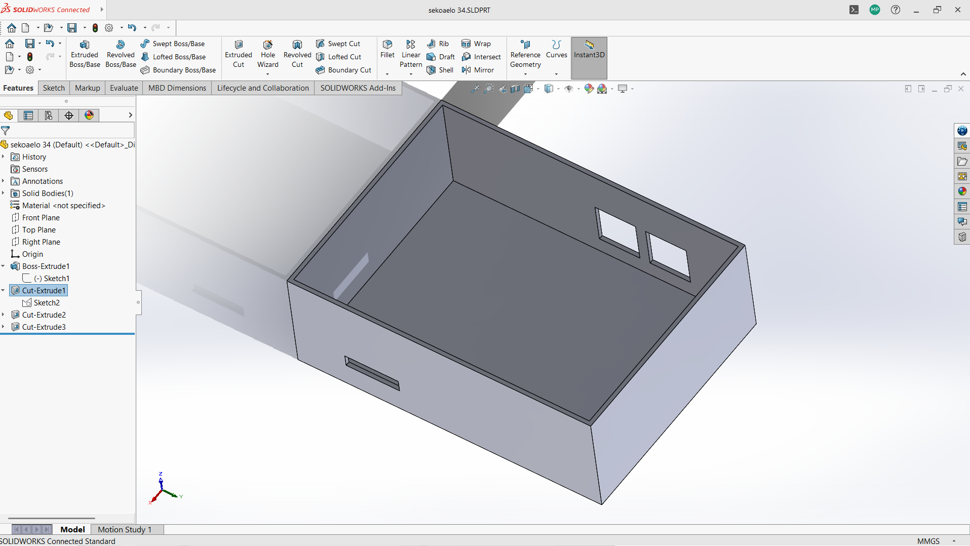
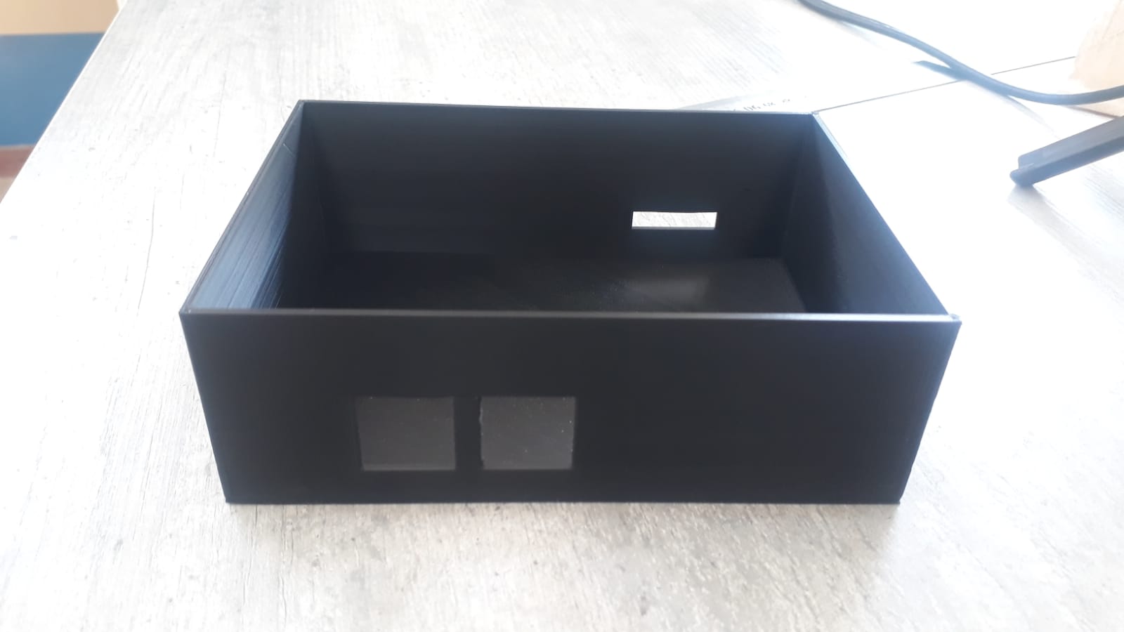
- Monitoring display box
- Circuit mounting box
- Datasheets: NE555G, 2SC5200, LM7805, etc.
- KiCad documentation for PCB design
- IEEE papers and YouTube for gate driver design, current control
- VESC firmware, open-source controller schematics, Elcircuits
- Fab Academy tutorials on electronics production, 3D modeling
| Component | Type | Source | Est. Cost ($) |
|---|---|---|---|
| Power Transistor | 2SC5200 | Communica (Pty) Ltd South Africa | 0.85 |
| Voltage Regulator IC | LM7805 | Communica (Pty) Ltd South Africa | 0.38 |
| Temperature Sensors | 24V | Nyerekatech | 3.46 |
| Microcontroller | Seeed XIAO RP2040 | Nyerekatech | 7.62 |
| Capacitors | Bulk X 10 | Communica (Pty) Ltd South Africa | 2.5 |
| Resistors/Diodes | Assorted pack | Communica (Pty) Ltd South Africa | 0.66 |
| PCB | Custom fab (1-layer, FR4 copper) | From inventory | |
| Heat Sink | Aluminum | Scrap | |
| Battery | 3.7V X 18 Li-ion | Takealot South Africa | 41.04 |
| Display | 16x2 I2C / OLE | Nyerekatech | 6.23 |
| Motor | 24V, 20A, 300rpm | Amazon.com | 38.99 |
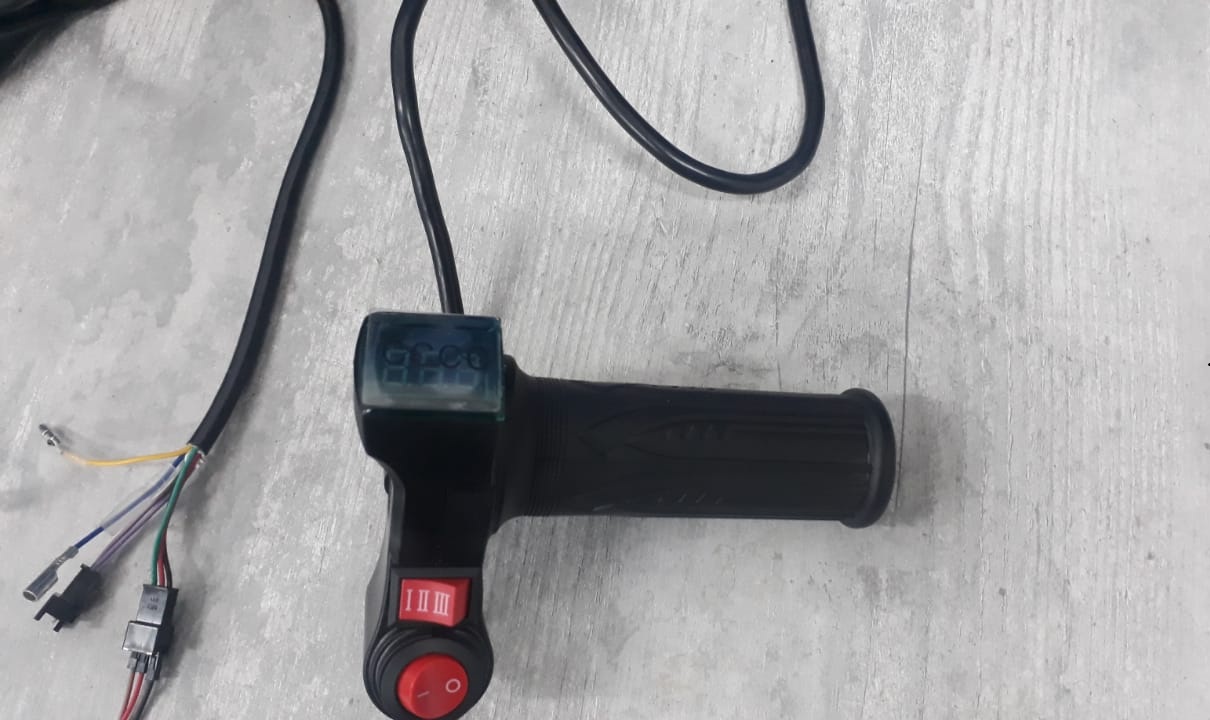
| Throttle | 5V output signal | Amazon.com | 14.99 |

| Unit | Process Used |
|---|---|
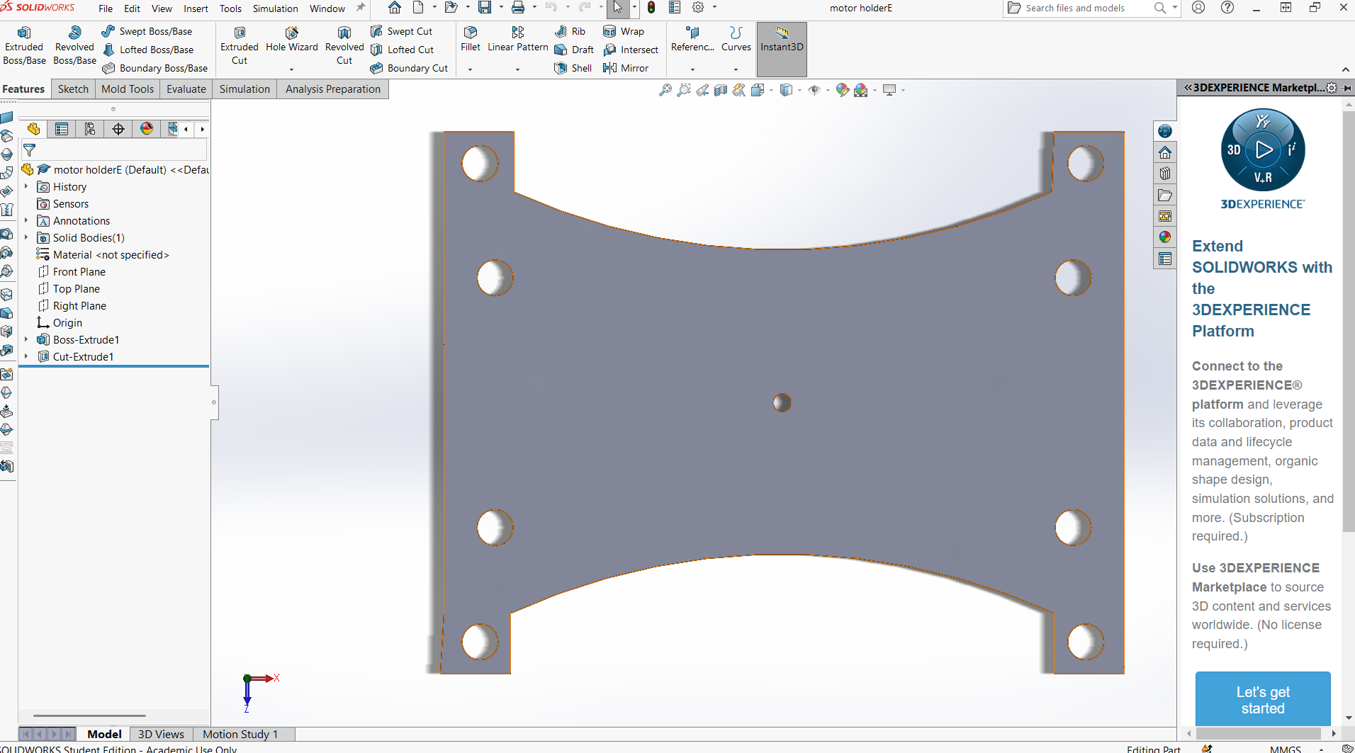
| 2D/3D Design | Enclosure and mount in SolidWorks |
| Additive Fabrication | 3D printing for enclosures |
| Subtractive Fabrication | CNC milling for metal sheet mount |
| Electronics Design | KiCad schematic + PCB layout |
| Production | PCB milling |
| Embedded Programming | C++ with Arduino IDE (Xiao RP2040) |
| Interfacing | Throttle, sensors, OLE |
| System Integration | Full wiring and mechanical assembly |
- Will it use PWM for motor speed control?
- Will it support both brushed and BLDC motors?
- Can the microcontroller handle real-time monitoring and control?
- What kind of failsafe and recovery strategy will be implemented?
- OLED display The screen cracked that was used to display speed, temperature, battery.
| Evaluation Metric | Criteria |
|---|---|
| Functional Testing | Smooth throttle control, no overheating |
| Safety | Current limits enforced |
| Design Integration | Clean, compact layout; 3D-printed case |
| Embedded Logic | Sensor response, overvoltage/overtemp logic |
| Aesthetics and Packaging | Finished housing and mounted connectors |
| Documentation | Full BOM, schematics, code, photos, videos |
Motor holder: Cut from plasma cutting machine.
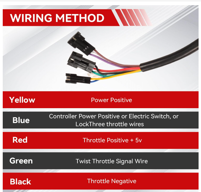
Throttle: The throttle has the ON switch which controls the power to the circuit board, provied signal to control the speed of the motor and displays the battery voltage.
Display Mounting: Made from PLA and pespex for visibility, 3D-printed with M3 screws, ensuring stability and visibility across riding conditions.
Power: USB-powered for prototyping (5V), with integration to a 24V-to-5V DC-DC converter (voltage regulator) for the full kit, ensuring sufficient runtime for extended rides.
Throttle System: Hall-effect signal and Seeed XIAO RP2040 (A0-D10 pins) ensure precise throttle control with exponential mapping for smooth response.
Monitoring: OLED display enables real-time data tracking (throttle, speed, battery, temperature, faults).
Fault Detection: The RP2040-based code for fault detection programmed to notify when errors and low battery detected, indicated by a red status LED.
Electronics: All components including battery are housed in a custom 3D-printed enclosure respectively, or a custom built container to protect against vibration, dust, and minor impacts during rides.
Safety Features: Includes throttle deadband (5%) to prevent jitter, exponential mapping for smooth acceleration, and fault-triggered torque cutoff for rider safety.
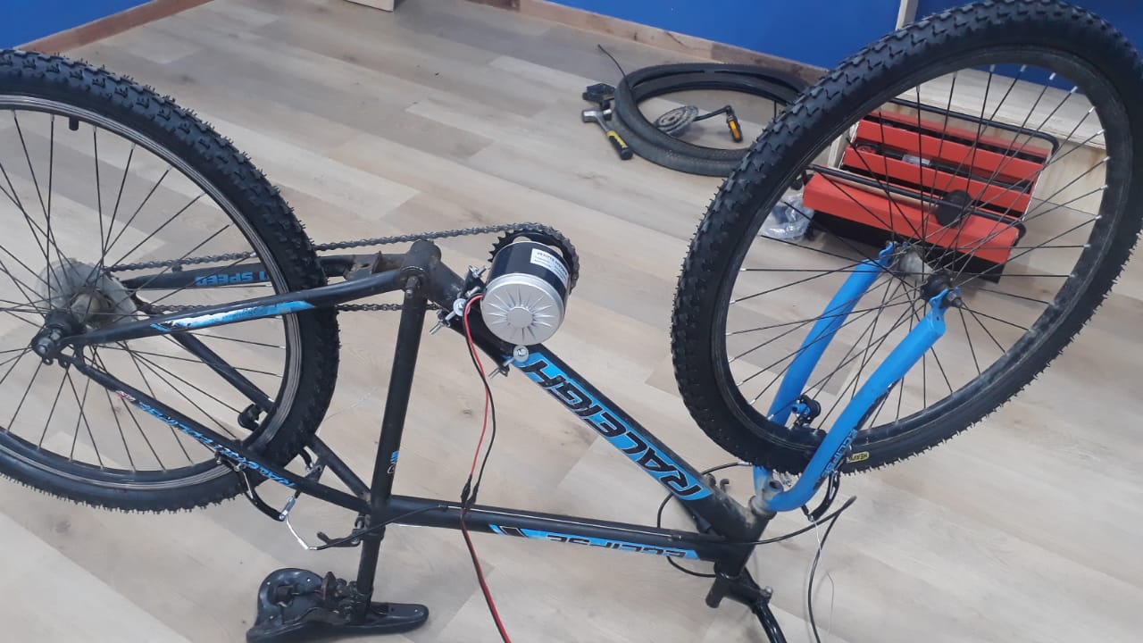
Assemling
- Assembling the motor Motor is assembed on the bi using motor mount and bold and nut.
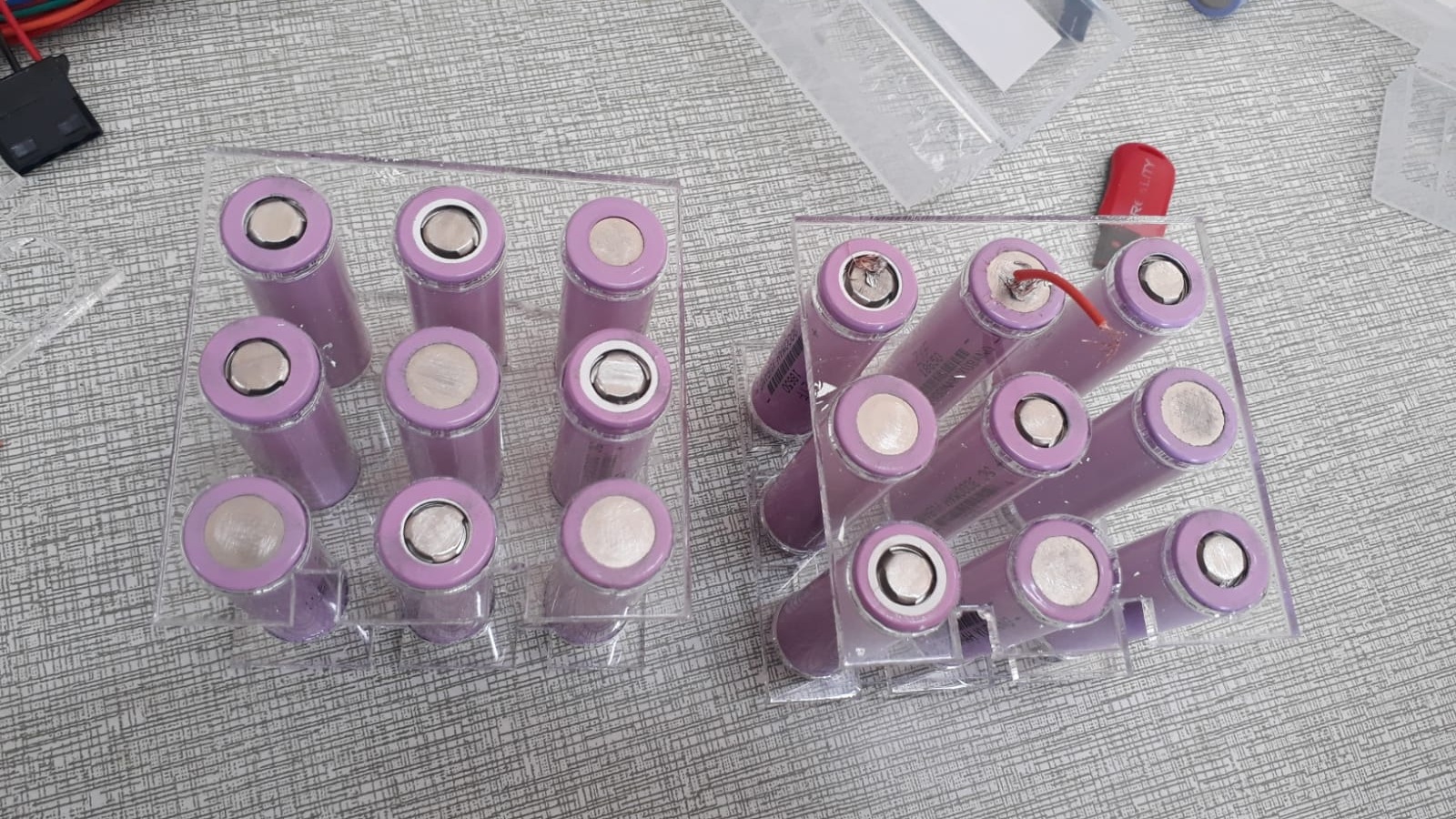
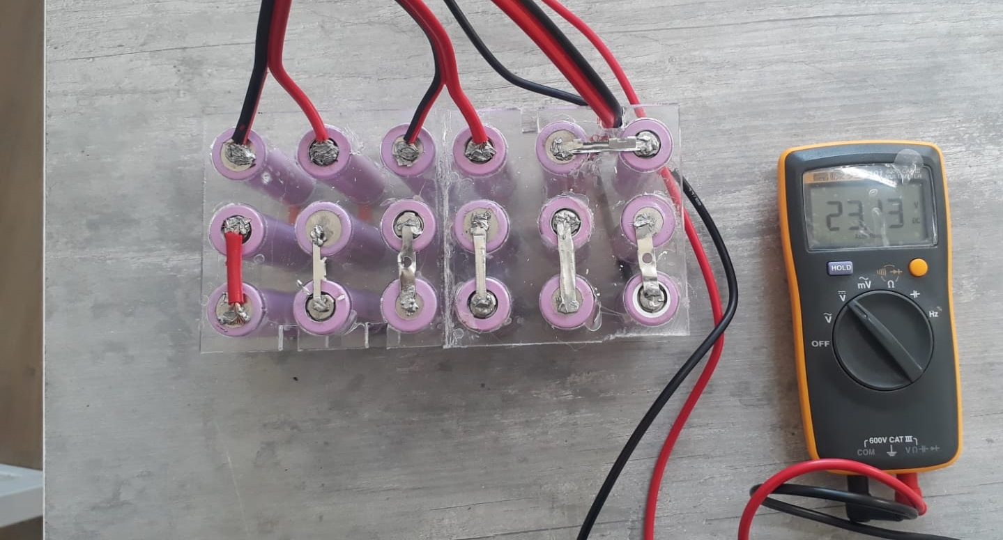
- Battery assembling Use battery holder and box made from pespex and soldered in a series (6sx3p) and parallel to achieve 24V.
- Circuit borad assembling
- MOSFET testing on breadboard
- Firmware testing
- Motor testing with throttle
- Motor testing without load
- FUll bike testing>
- My first Circuit board burnt due to Overcurrent on the traces, the solution was to design large trace for the high current.
- MOSFET malfunctioning, solve by changing the mulfunctioning MOSFET with new ones.
- My alternate screen did not power up, I had to re-order new screen.
- PCB milling machine not reading coordinate well, I had to learn the software controlling the machine.
Full conversion kit code
// === Include Required Libraries === #include// Core Arduino functionality #include // I2C communication for OLED #include // Graphics library for OLED #include // OLED display driver // === OLED Display Configuration === #define SCREEN_WIDTH 128 // OLED display width in pixels #define SCREEN_HEIGHT 64 // OLED display height in pixels #define OLED_RESET -1 // No reset pin used Adafruit_SSD1306 display(SCREEN_WIDTH, SCREEN_HEIGHT, &Wire, OLED_RESET); // === Hardware Pin Assignments === const int pwmPin = 3; // PWM output pin for motor (connected to MOSFET gate) const int throttlePin = A0; // Analog input for throttle (0–1023) const int batteryPin = 27; // Analog input for battery voltage sensing const int thermistorPin = D1; // Analog input for thermistor (temperature sensing) const int ledPin = 14; // LED pin for fault/status indication // === System Thresholds and Constants === const float lowBatteryVoltage = 10.0; // Minimum safe battery voltage (adjust as needed) const float maxMosfetTemp = 80.0; // Maximum MOSFET temperature in °C before fault // === Thermistor Parameters === const float BETA = 3950.0; // B value of thermistor const float R0 = 10000.0; // Thermistor resistance at 25°C const float T0 = 298.15; // 25°C in Kelvin const float R_REF = 10000.0; // Reference pull-up resistor void setup() { // === Initialize Serial Communication === Serial.begin(9600); // === Configure Pin Modes === pinMode(pwmPin, OUTPUT); pinMode(batteryPin, INPUT); pinMode(thermistorPin, INPUT); pinMode(ledPin, OUTPUT); digitalWrite(ledPin, LOW); // Start with LED off // === Initialize OLED Display === if (!display.begin(SSD1306_SWITCHCAPVCC, 0x3C)) { Serial.println(F("OLED init failed")); while (true); // Stop everything if OLED fails } // === Display Welcome Message === display.clearDisplay(); display.setTextSize(1); display.setTextColor(SSD1306_WHITE); display.setCursor(10, 20); display.println("Motor Controller Ready"); display.display(); delay(2000); // Wait for 2 seconds before starting main loop } void loop() { // === Read Throttle (0 to 1023) === int throttleValue = analogRead(throttlePin); // === Calculate PWM Value from Throttle === int pwmDuty = map(throttleValue, 0, 1023, 0, 255); // Map to 8-bit PWM (0–255) analogWrite(pwmPin, pwmDuty); // Output PWM to motor controller // === Simulate Speed (for display) === float speed = map(throttleValue, 0, 1023, 0, 50); // speed in km/h (adjust as needed) // === Measure Battery Voltage === float adcBattery = analogRead(batteryPin); // Read battery ADC value float batteryVoltage = (adcBattery / 1023.0) * 3.3 * (100.0 + 10.0) / 10.0; // ↑ Adjust if using a different resistor divider (here 100k:10k assumed) // === Read Thermistor and Calculate Temperature === int adcTherm = analogRead(thermistorPin); // Thermistor ADC read float resistance = R_REF * (1023.0 / adcTherm - 1.0); // Calculate thermistor resistance float temperature = 1.0 / (log(resistance / R0) / BETA + (1.0 / T0)) - 273.15; // °C // === Show All Data on OLED Display === displayStatus(throttleValue, pwmDuty, batteryVoltage, temperature, speed); // === Print Status to Serial Monitor === Serial.printf("Throttle: %d, PWM: %d, Speed: %.1f km/h, Battery: %.2f V, Temp: %.1f C\n", throttleValue, pwmDuty, speed, batteryVoltage, temperature); // === Wait for a Bit Before Next Update === delay(500); // Update rate every 0.5 second } // === Display Normal Operating Status on OLED === void displayStatus(int throttle, int pwm, float voltage, float temp, float speed) { display.clearDisplay(); // Clear the OLED display.setCursor(0, 0); // Reset cursor to top-left display.setTextColor(SSD1306_WHITE); // Set text color display.setTextSize(1); // Set font size (small) // Print all values display.printf("Throttle: %4d\n", throttle); display.printf("PWM: %3d\n", pwm); display.printf("Battery: %.2fV\n", voltage); display.printf("Temp: %.1f C\n", temp); display.printf("Speed: %.1f km/h\n", speed); display.display(); // Update the OLED with new content }