Group Project: CNC Drawing Machine
Introduction
As part of the group project for Fab Academy 2025, we designed and built a CNC machine capable of drawing on paper using a pen mounted on the Z-axis. This drawing CNC uses stepper motors and belts to move in the X and Y directions, and a servo to lift and lower the pen. The project required the integration of mechanical design, electronics, and programming to bring the machine to life.
Proccess of making the CNC
Teammates


CNC Project Timeline
Period: April 9 - 23, 2025
Final Delivery: April 23
| Date | Activity | Responsible(s) |
|---|---|---|
| April 9 - 11 | Electronic design of the control boards in KiCad | Javier Osorio |
| April 12 | Fabrication of the electronic boards (3 in total) | Javier Osorio |
| April 13 - 16 | Complete mechanical design of the CNC (structure, axes, motors) | Paula Rivero & Saúl Jarquin |
| April 17 - 18 | Mechanical assembly of the structure | Paula Rivero & Saúl Jarquin |
| April 19 - 21 | Programming the code to control the CNC and make it draw | Marilú |
| April 22 | Final tests and system integration | Entire team |
| April 23 | Final delivery and demonstration | Entire team |
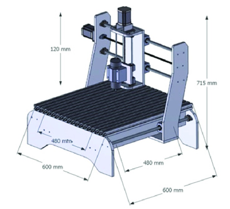
First Design
To design the structure of the CNC, we found this image of a CNC model with measurements. The dimensions and overall shape of the structure served as a useful reference to guide the design of our own CNC.
For the holes, we considered the dimensions of the bearings to place them correctly within the structure, allowing the 8mm Acme screw to pass and rotate smoothly without interference.Later on , we present the bearing plane
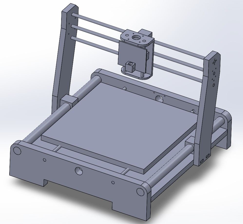
As part of the initial design process, we created individual structural parts and assembled them virtually. This helped us visualize the shape and proportions of the CNC.
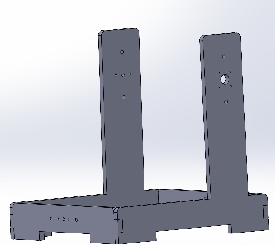
ReDesign Process in SolidWorks
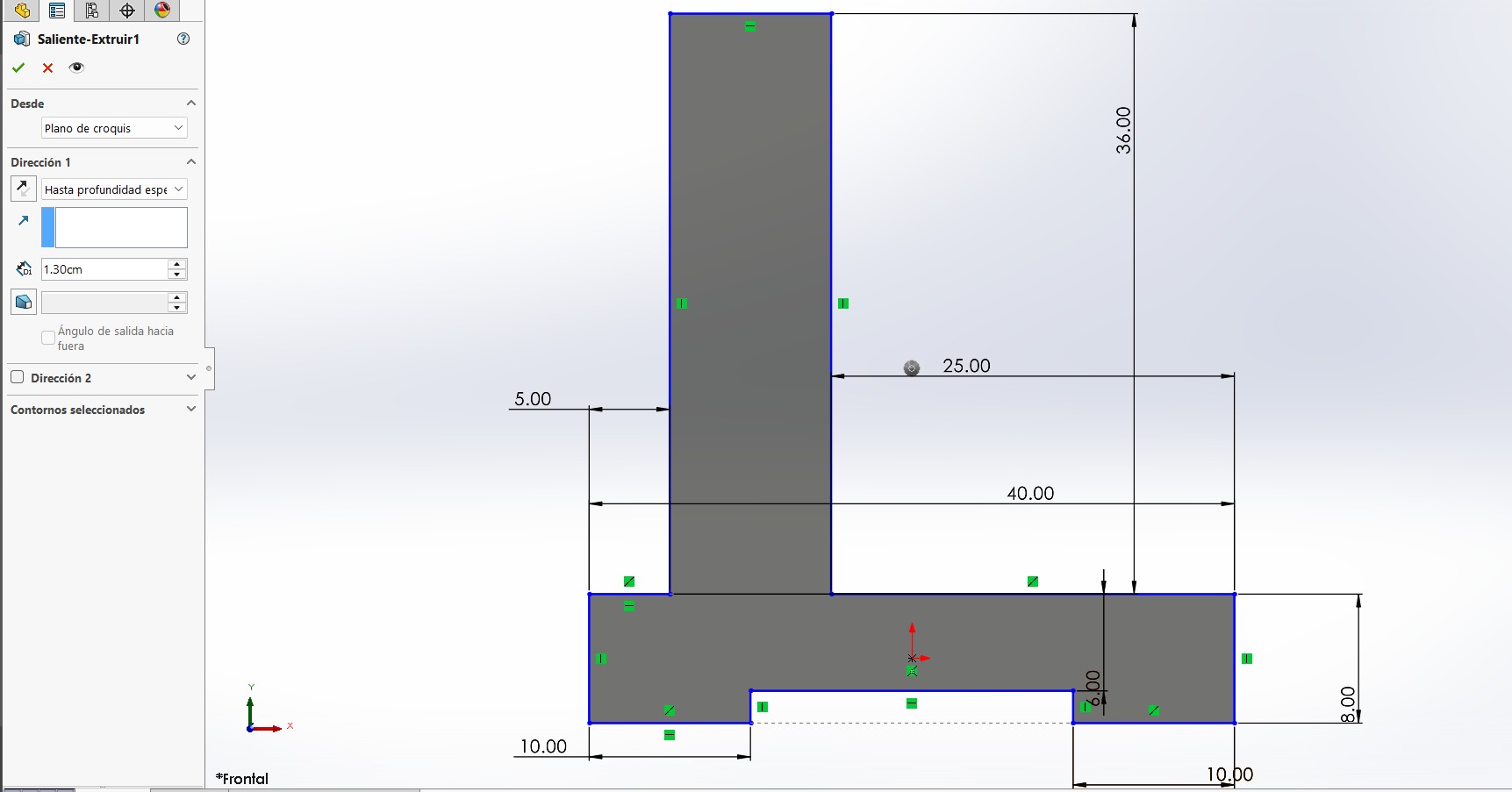
Before anything else, I used SolidWorks in centimeters, as it was easier for me to visualize the measurements this way than in millimeters.
I first created a sketch using the tools Smart Dimension, Center Rectangle, and Trim Entities (Scissors). This shape would become the side panels of the CNC. Then, I extruded the sketch to match the thickness of the material, which is 1.3 cm. I also used the Fillet tool to round the corners and make the design smoother and safer to handle.
It’s important to remember that each side will contain different components. On one side, there will be a NEMA 17 motor and aluminum guides; on the opposite side, there will be a bearing block (chumacera) with a circular bearing.
Bearing Block Side
To design this side, we based it on the technical drawing of the KFL-08 bearing block (8 mm).
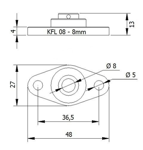
Using this diagram, we created another sketch. I spaced the screw hole and the guide holes 5 cm apart to allow smooth movement and leave enough space for the mechanism. At the bottom, We added the connecting slots where the other pieces will be inserted—also with a thickness of 1.3 cm, matching the material. I then used the Fillet tool to round the external corners, improving the aesthetics and safety of the part.
Finally, I made a cut through the part to finish shaping the side panel.
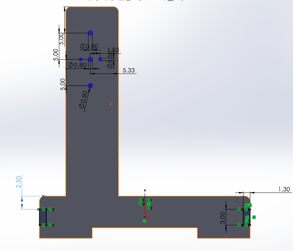
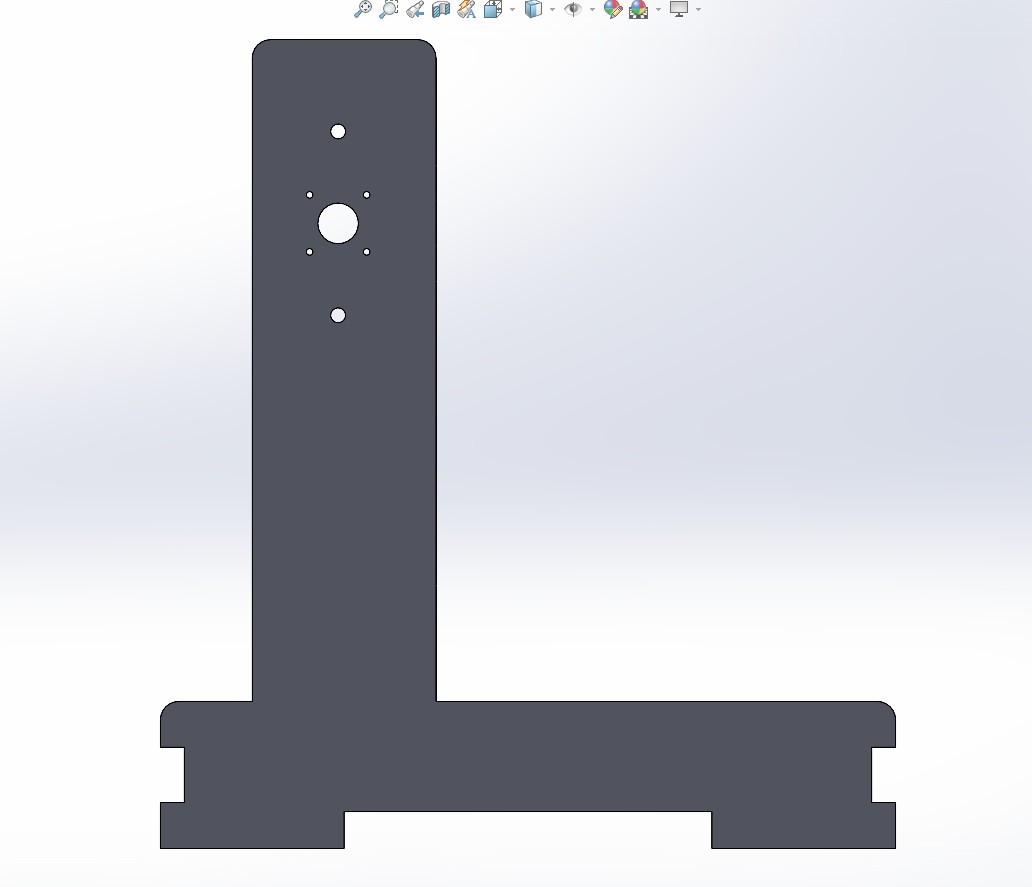
NEMA 17 Motor Side
This side is similar to the bearing block side in shape and structure, but it includes the necessary holes and mounting space for the NEMA 17 stepper motor.
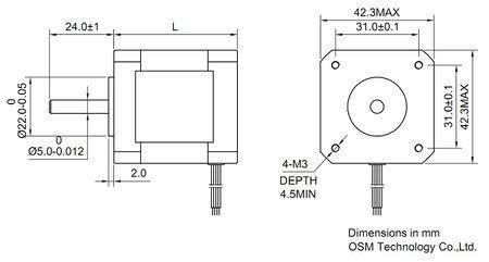
Using the NEMA 17 technical drawing, I created a new sketch in SolidWorks. We placed the motor mount holes at the center, aligned with the guide holes. Just like the other side, I kept 5 cm of separation between the motor hole and the aluminum guide holes to ensure smooth mechanical movement and enough space for the components. At the bottom, I added the notches for connecting to the rest of the CNC structure, with a matching material thickness of 1.3 cm. I also applied the Fillet tool to the corners to match the smooth design of the opposite side.
And with that, the NEMA 17 motor side of the CNC is complete.
Base Joints
After designing the side panels,we created the other two base joints following the same steps, only adjusting the dimensions to fit their placement in the structure. In this case, instead of cutting holes for tabs, I modeled the tabs themselves to connect with the previous parts. Again, the thickness used was 1.3 cm.
This is the base design for both pieces, as they share the same structural logic and only differ in size and the components they include.
And this is the structure assembly:
Preparing Files in VCarve and CNC Cutting
Once we had all the parts designed in SolidWorks with the correct measurements, we exported them as DXF files to be used in VCarve.
You can download a trial version of VCarve from the official Vectric website:
https://www.vectric.com/products/vcarve
Setting Up in VCarve
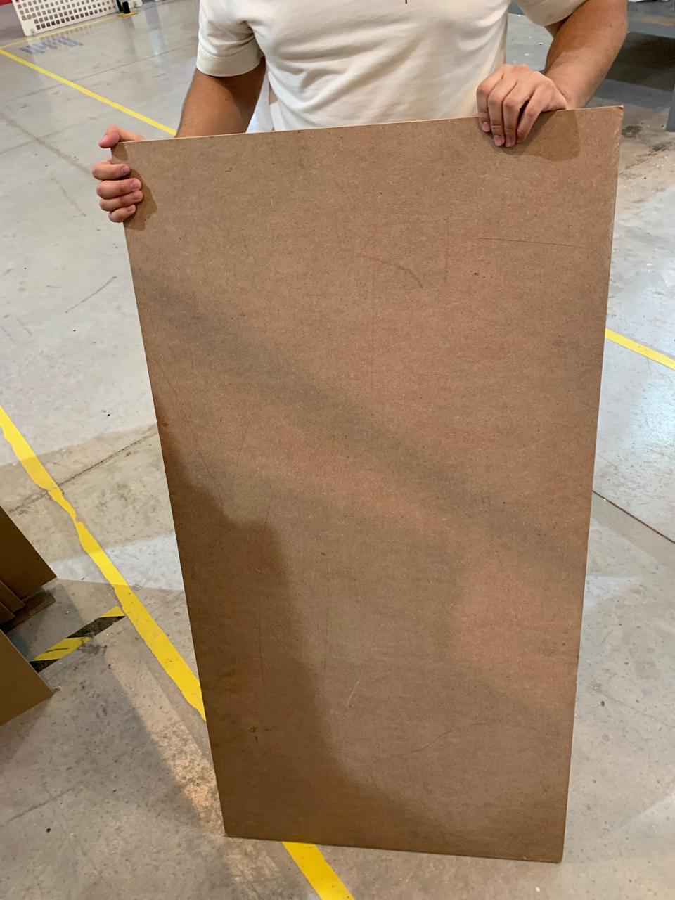
The material we used , MDF, heres a picture of the material we used:
In VCarve, I created a new job with the following settings:
- Job Size: 60 cm x 30 cm
- Material Thickness: 1.3 cm
- Units: Centimeters
- Z Zero Position: Top of the material
I imported the DXF files and arranged the parts to fit within the job area. Then, I set the toolpaths:
- Tool: End Mill 1/8 inch (3.175 mm)
- Cut Depth: 1.4 cm (to ensure it cuts through the material)
- Pass Depth: 0.3 cm
- Feed Rate: 60 mm/s
- Plunge Rate: 30 mm/s
- Toolpath Type: Profile cut (Outside)
Exporting and Machining
Once everything was ready, I calculated the toolpaths and exported the G-code using the post-processor for our CNC machine . I saved the toolpath file as a .sbp file.
I secured the 1.3 cm material board on the CNC bed using screws on the corners and zeroed the X, Y, and Z axes on the top-left corner of the material.
With everything set, I ran the job and carefully monitored the machine during the entire cutting process.
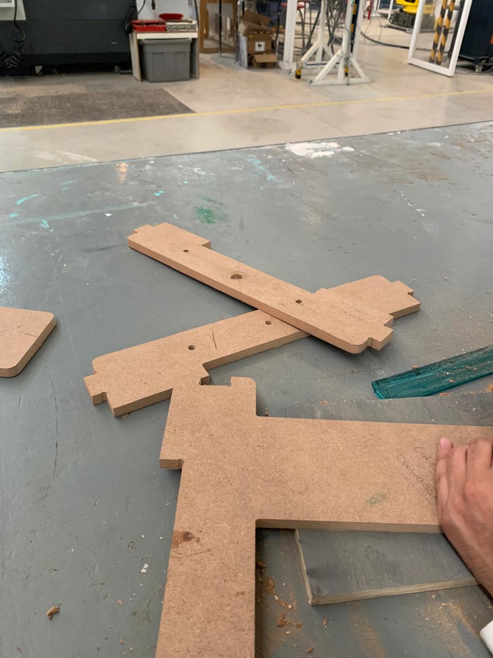
Post-Processing
Once the CNC finished cutting, I made sure all joints fit together correctly, and I tested the assembly of the CNC sides and base.
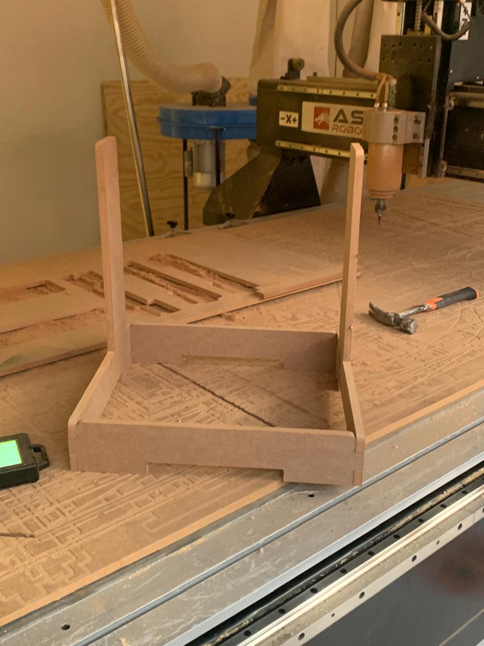
However, the machine did not cut the holes as expected. Because of this, we had to make the holes manually.
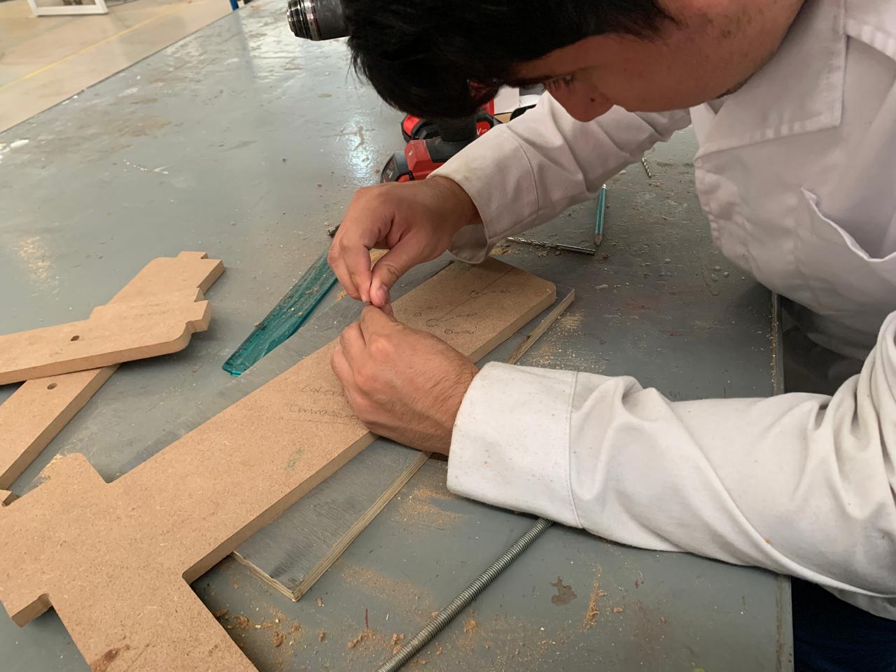
The final result, with the motor and the bearing blocks (chumaceras) installed, looked like this:
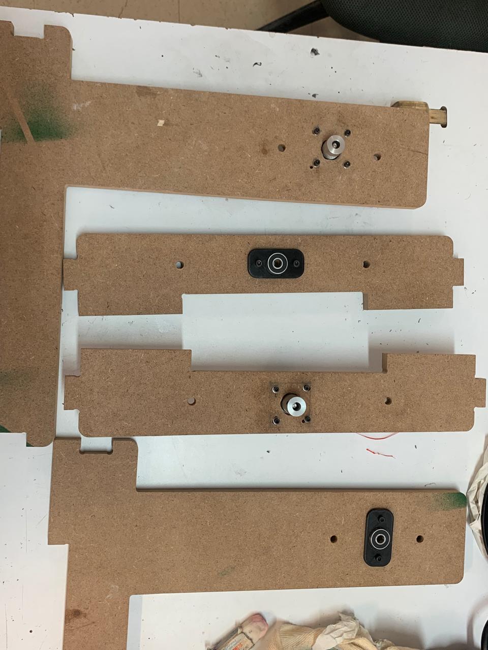
Note
In the end, since there were no KFL-08 bearing blocks available, I had to design one in SolidWorks using the same dimensions and a circular bearing.
Original Design Files and Laser Cutting Files
Below you can find the original design and laser cutting files:
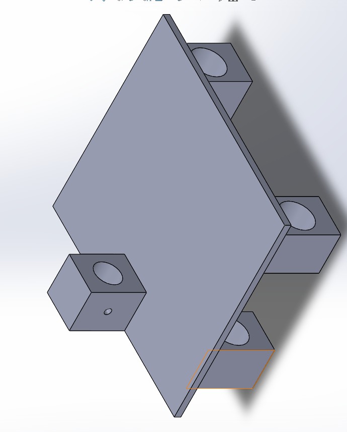
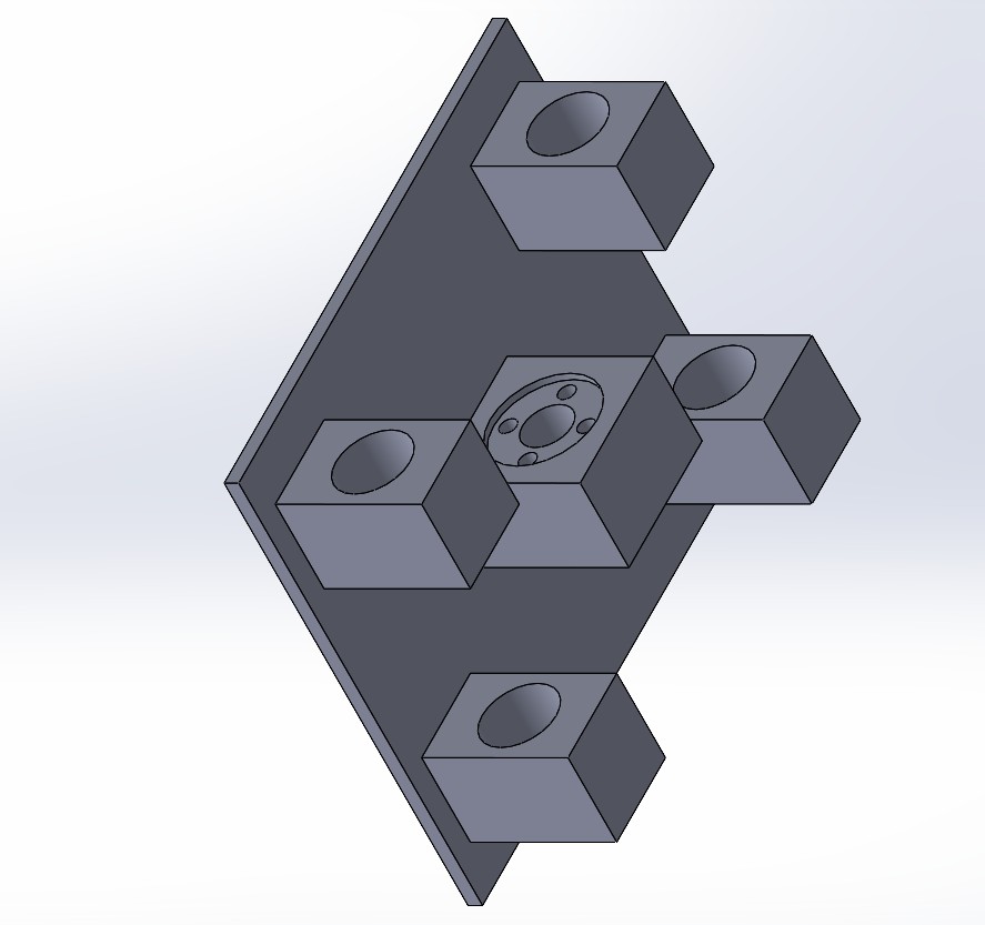
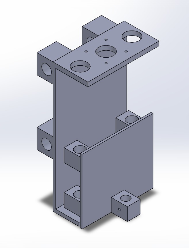
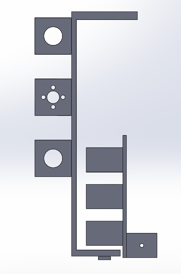
Axis Design in SolidWorks
To better understand and organize the movement of each axis in the CNC machine, I designed the key components of the X, Y, and Z axes using SolidWorks. This helped visualize how each axis interacts within the full assembly and confirm the range of motion for each part.
🔵 X Axis – Gantry (Left to Right)
The X axis consists of a rigid gantry that supports the Z axis assembly. It allows movement from left to right along the width of the machine. In the SolidWorks model, this is represented by a horizontal beam with guide rails and linear bearings for smooth movement.
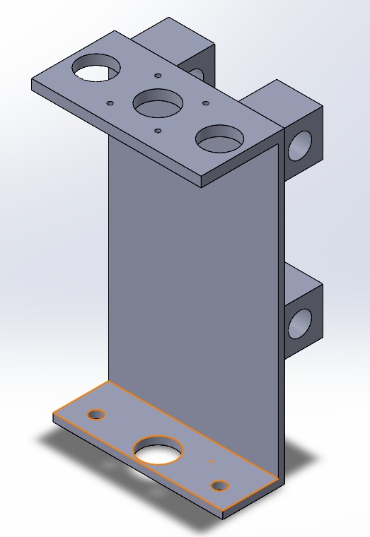
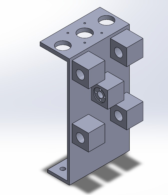
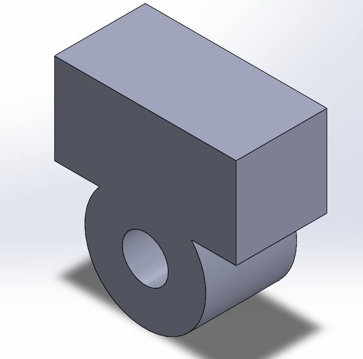
This part was carefully designed using real component dimensions to ensure a proper fit during assembly:
- Overall Dimensions: 200 mm tall, 110 mm deep (extrusion), 50 mm long at the top, 40 mm at the base, and 4 mm wall thickness.
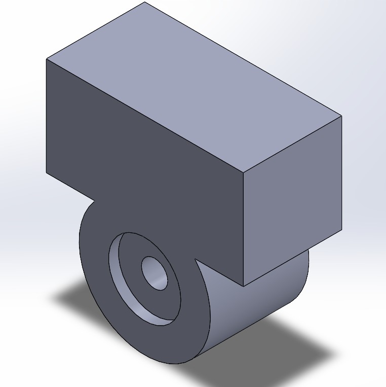
- Top Section: Includes a dedicated space for mounting a NEMA 17 stepper motor and two circular bearing cutouts (left and right) to stabilize the shaft and improve fluid motion.
- Bottom Section: Also includes aligned circular bearing mounts for additional support.
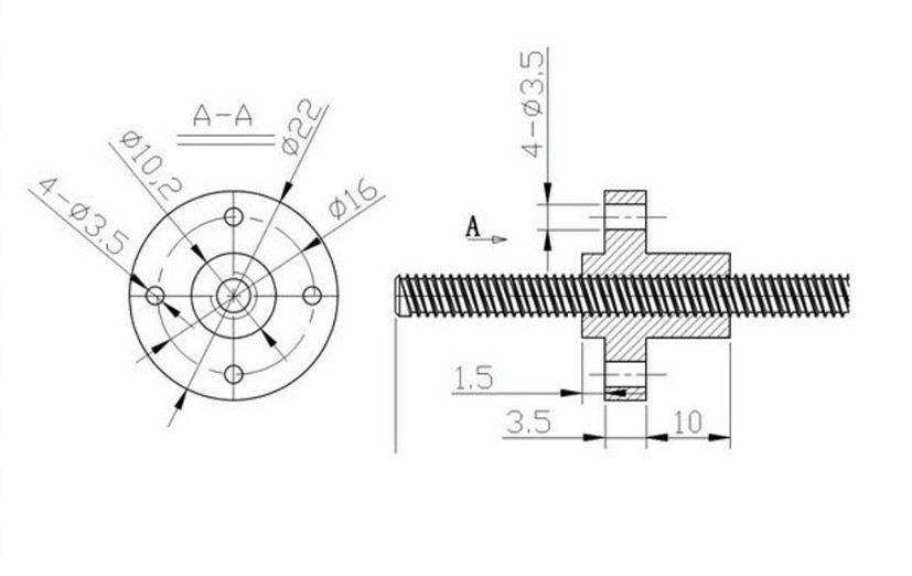
- Back Center: A rectangular space was added for the installation of a T8 nut, which allows the leadscrew-driven movement of the Z-axis assembly.
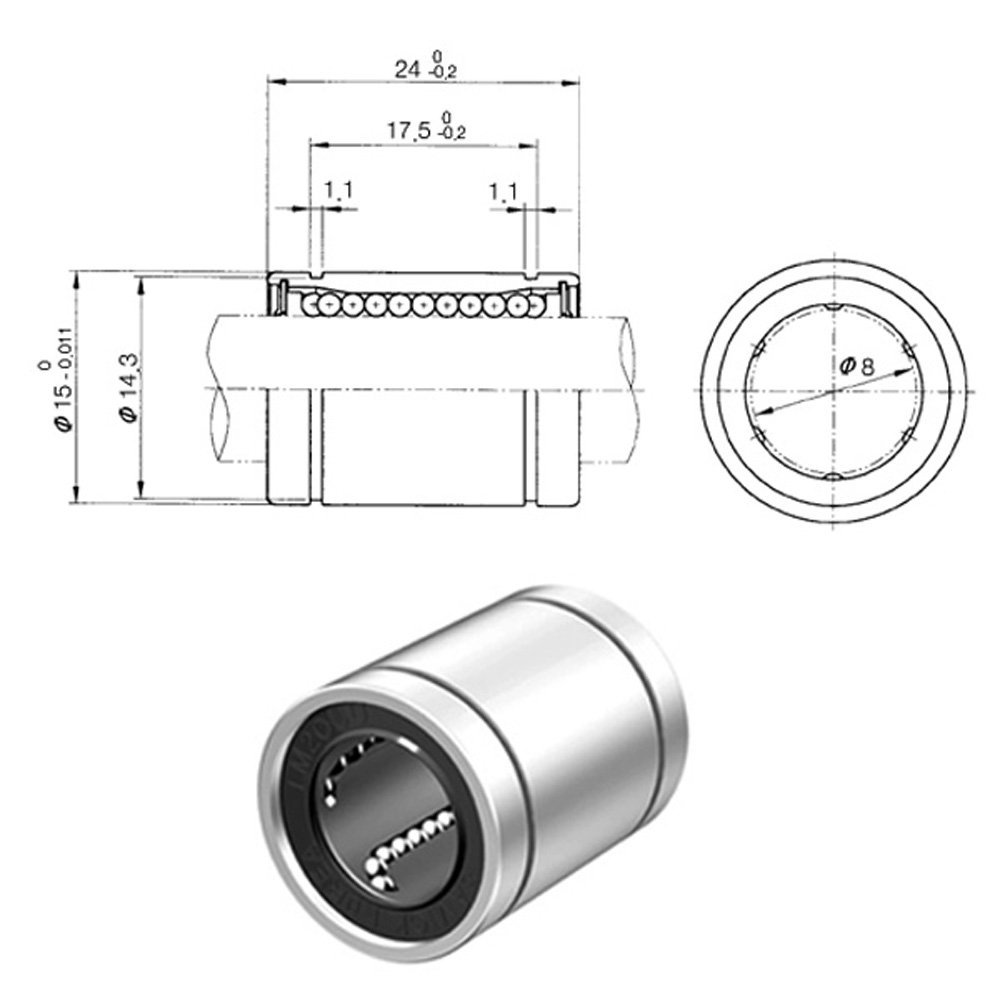
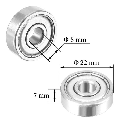
- Back Top and Bottom: Two 15.22 mm diameter cylindrical holes were created to house LM8UU linear bearings (8×15×24 mm), based on the technical drawing of this bearing. These guide the 8 mm shafts used for lateral motion.
Design References: The dimensions for these cutouts were based on the official mechanical drawings of the LM8UU linear bearings and the T8 brass nut, ensuring compatibility and precision during the mechanical assembly.
Reference Drawings
🔴 Y Axis – Bed Movement (Forward and Backward)
In this CNC configuration, the bed itself moves forward and backward, making it the Y axis. This is a classic design in fixed-gantry machines. In SolidWorks, the bed was modeled with mounting holes and space for the linear guides and motor that drive its motion.
For the construction of the Y-axis, I designed and printed a total of 5 support pieces to hold and guide the movement of the bed:
- 3 Central Pieces: Placed under the bed's center area. These include 15.22 mm diameter cylindrical holes designed to house LM8UU linear bearings (8×15×24 mm), allowing smooth motion along the 8 mm guide rails.
- 2 Side Pieces: Positioned at the lateral ends of the bed. These were designed to support circular 8 mm bearings, helping to stabilize the shaft at both ends and ensuring improved rotational movement.
All parts were modeled in SolidWorks based on the technical dimensions of the LM8UU bearing and T8 nut to ensure a precise fit. The components were printed in 3D using a Prusa printer with 15% infill density, providing a good balance between strength and weight.
For the bed itself, we used a 40 cm × 40 cm MDF board to provide a flat and stable platform. Since we needed the surface to remain smooth and undamaged, I chose strong adhesive glue to attach the printed support pieces instead of screwing them in. This method preserved the flatness of the MDF and still provided sufficient stability for the bed’s movement.
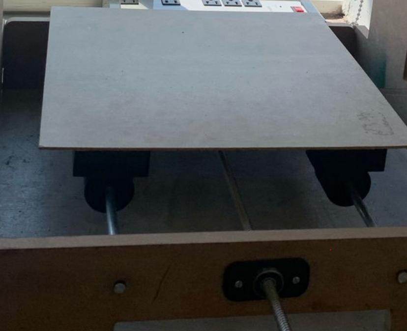
The modular setup allows precise alignment of the components, facilitating smooth and consistent motion along the Y-axis.
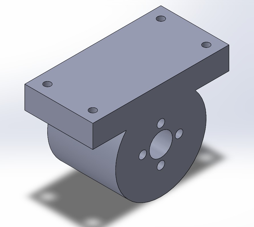
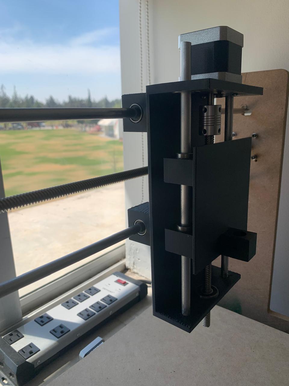
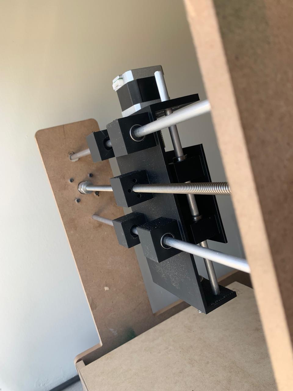
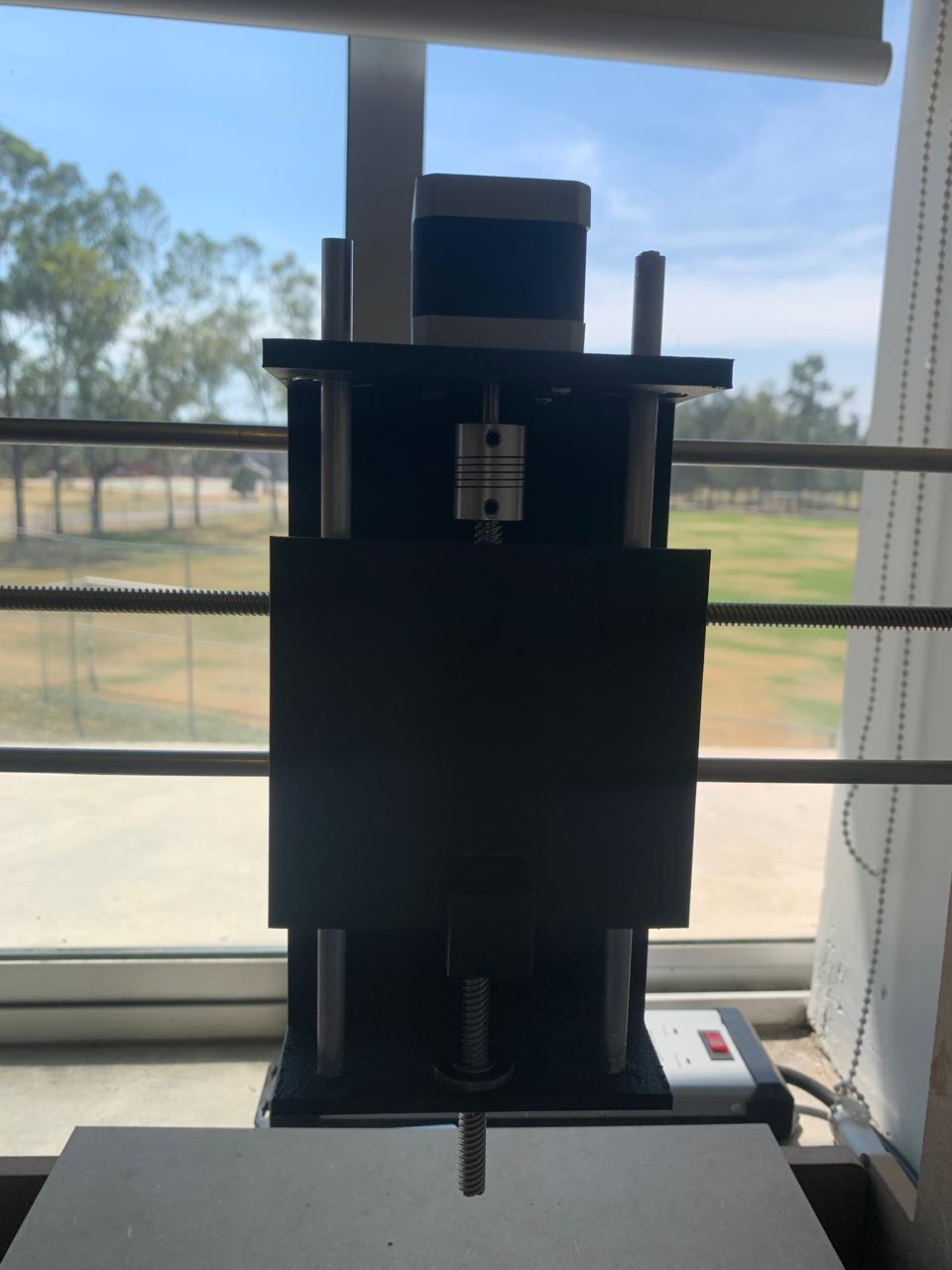
🟢 Z Axis – Pen Mount and Vertical Motion
For the Z axis, I designed a vertical carriage specifically adapted to hold a fine-tip Sharpie marker, ensuring precision in drawing tasks. I based the cylindrical cutout on the diameter of the marker, which is approximately 12.5 mm. To secure the marker in place, I added two M3 screw holes on the sides.
The rear part includes a mounting space for a T8 leadscrew nut to control vertical motion precisely. We also added corner cutouts to hold 4 linear bearings (LM8UU), one on each side, for smooth and stable vertical movement.
- Marker Holder Diameter: ~12.5 mm (Sharpie fine tip)
- Side Holes for Screws: 3 mm (M3 size)
- Rear Nut Slot: Designed for standard T8 nut (square flange type)
- Linear Bearing Slots: Four 15.22 mm diameter holes for LM8UU bearings (8×15×24 mm)
- Overall Plate Dimensions: 100 mm × 110 mm, 3 mm thick
To verify the fit and alignment of the holes, I assembled the Z axis carriage with the X axis slider. This test was crucial to ensure that the linear bearings and the T8 screw mount aligned correctly before printing the final version.
All parts were 3D printed using a Prusa printer with 15% infill for a balance between strength and print speed. This setup ensures stable vertical control of the Sharpie, essential for the CNC’s drawing functionality.
📁 Design Files by Axis
🟥 X Axis
- Download X Axis – Gantry (Left to Right) – Includes 3D models and technical drawings of the gantry components.
🟩 Y Axis
- Download Y Axis – Bed Movement (Forward and Backward) – Contains design files for the moving bed and its support parts.
🟦 Z Axis
- Download Z Axis – Pen Mount and Vertical Motion.zip – Includes the pen holder design and the components for vertical movement.
These SolidWorks models were essential for planning the assembly process and ensuring proper alignment of all components before manufacturing.
Installing Leadscrews and Aluminum Shafts
With the T8 leadscrews and aluminum shafts prepared, I proceeded to install them into the CNC's frame. The leadscrews were mounted on the X and Y axes to enable smooth and precise movement. I carefully aligned the shafts to avoid any misalignment that could affect the machine's performance.
I used the pre-drilled holes in the frame for the leadscrew mounts. For the aluminum shafts, I inserted them into the corresponding bearings to ensure minimal friction. It’s important to keep the shafts well-lubricated to prevent wear over time.
After securing the leadscrews and shafts, I checked for any play in the motion and made minor adjustments to ensure everything was tight and stable.
Here’s a picture showing the installation of the leadscrews and shafts.
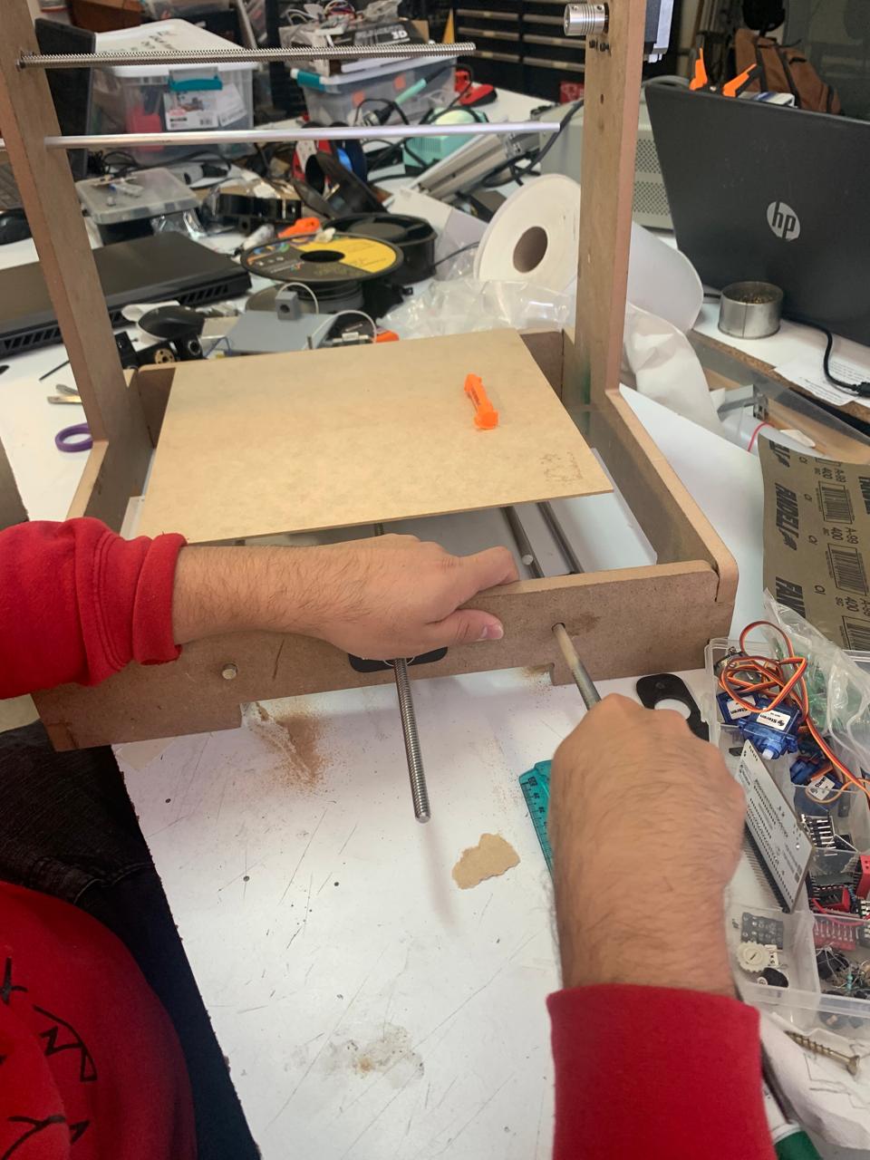
- Leadscrews: Installed on X and Y axes for linear movement.
- Linear Shafts: Inserted into bearings for smooth motion.
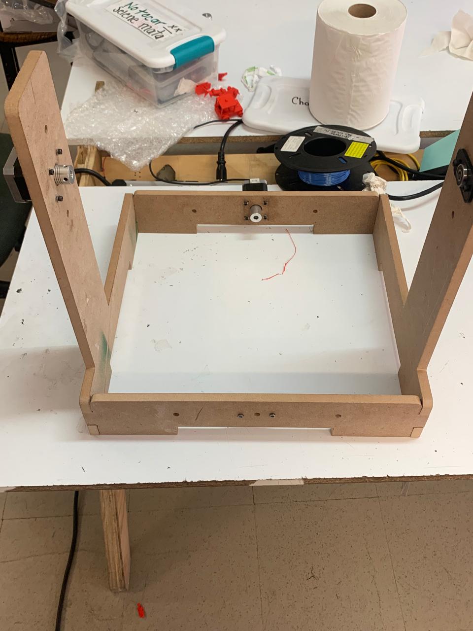
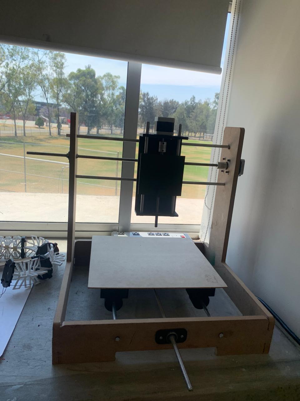
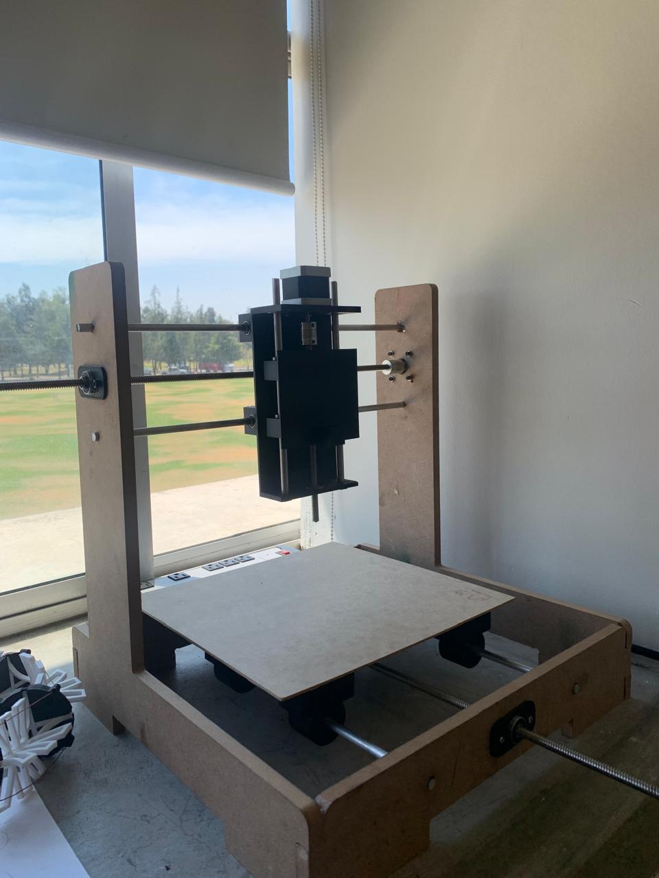
Final Assembly of the CNC
After completing the installation of the leadscrews, aluminum shafts, and other components, we assembled the CNC structure. The assembly includes the X and Y axes with all the necessary motors and supports. The frame is now ready to be tested and calibrated for precise movement and performance.
Below is the image showing the final assembly of the CNC machine with all components in place.
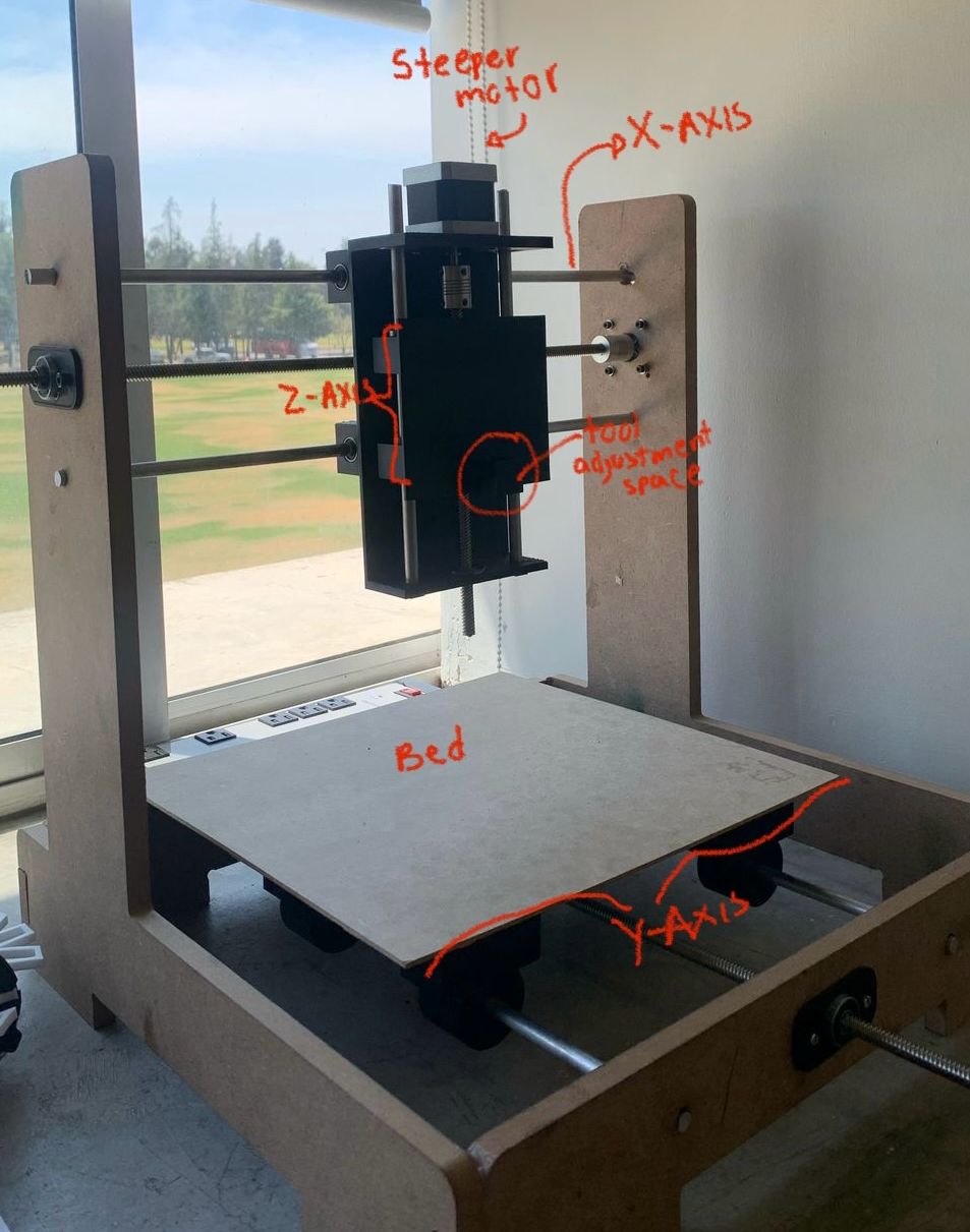
Mechanical
Mechanically, the machine consists of:
- X and Y axes driven by NEMA 17 stepper motors.
- GT2 timing belts and pulleys for precise motion transmission.
- 8 mm smooth rods and linear bearings for smooth movement.
- A spring-mounted pen holder with a micro servo for lifting/lowering the pen.
Electronics
The CNC machine uses an ESP32 microcontroller, which controls two stepper motor drivers (A4988) for the X and Y axes and a micro servo motor for the Z-axis (pen). The power supply delivers enough current to drive all components, and the wiring was organized to avoid signal interference.
Designed in KiCad and milled using the Monofab.
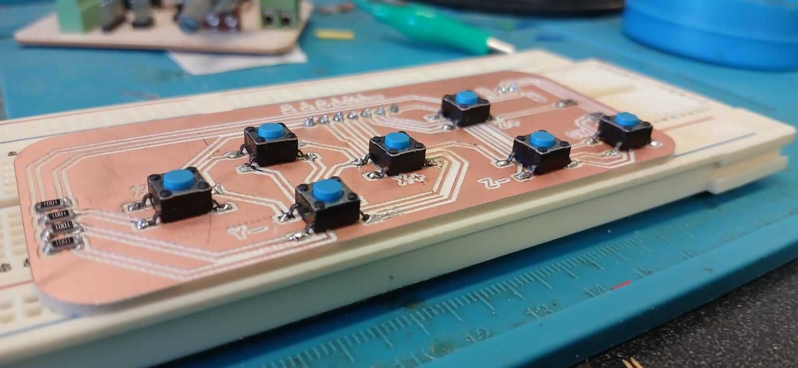
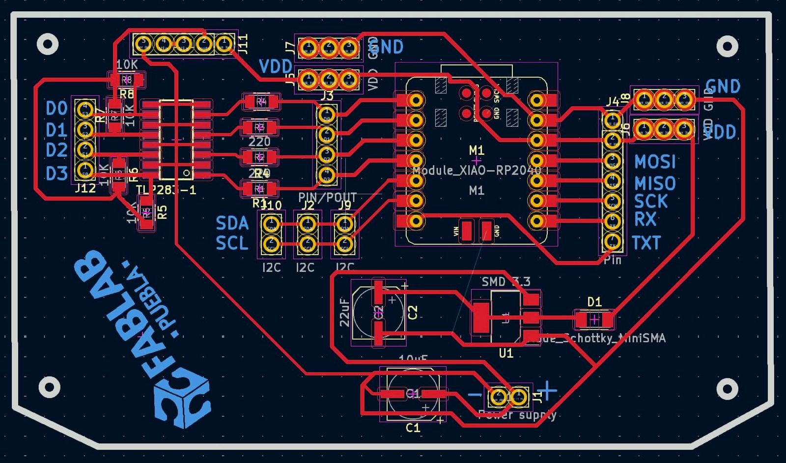
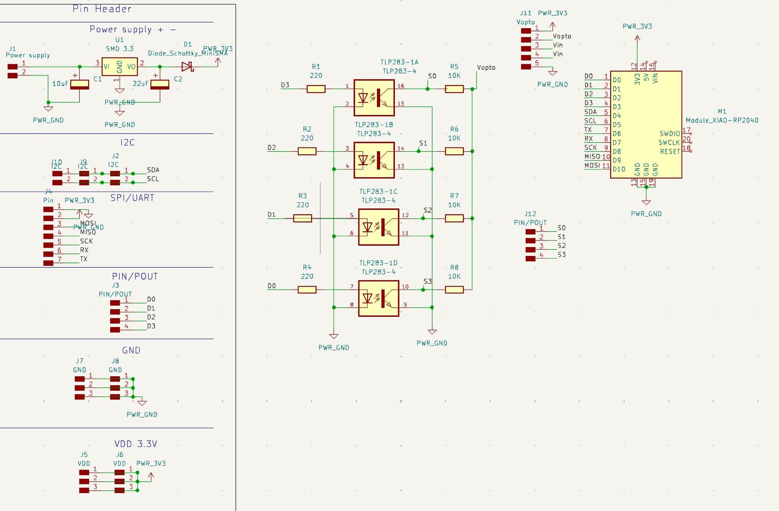
The electronic design process began by defining the required components and connections for controlling the CNC. The schematic was created in KiCad, carefully placing the ESP32 microcontroller, the stepper motor drivers, the micro servo, and the necessary connectors. After verifying the electrical connections and pin assignments, the PCB layout was developed, routing the traces to minimize interference and ensure efficient operation.
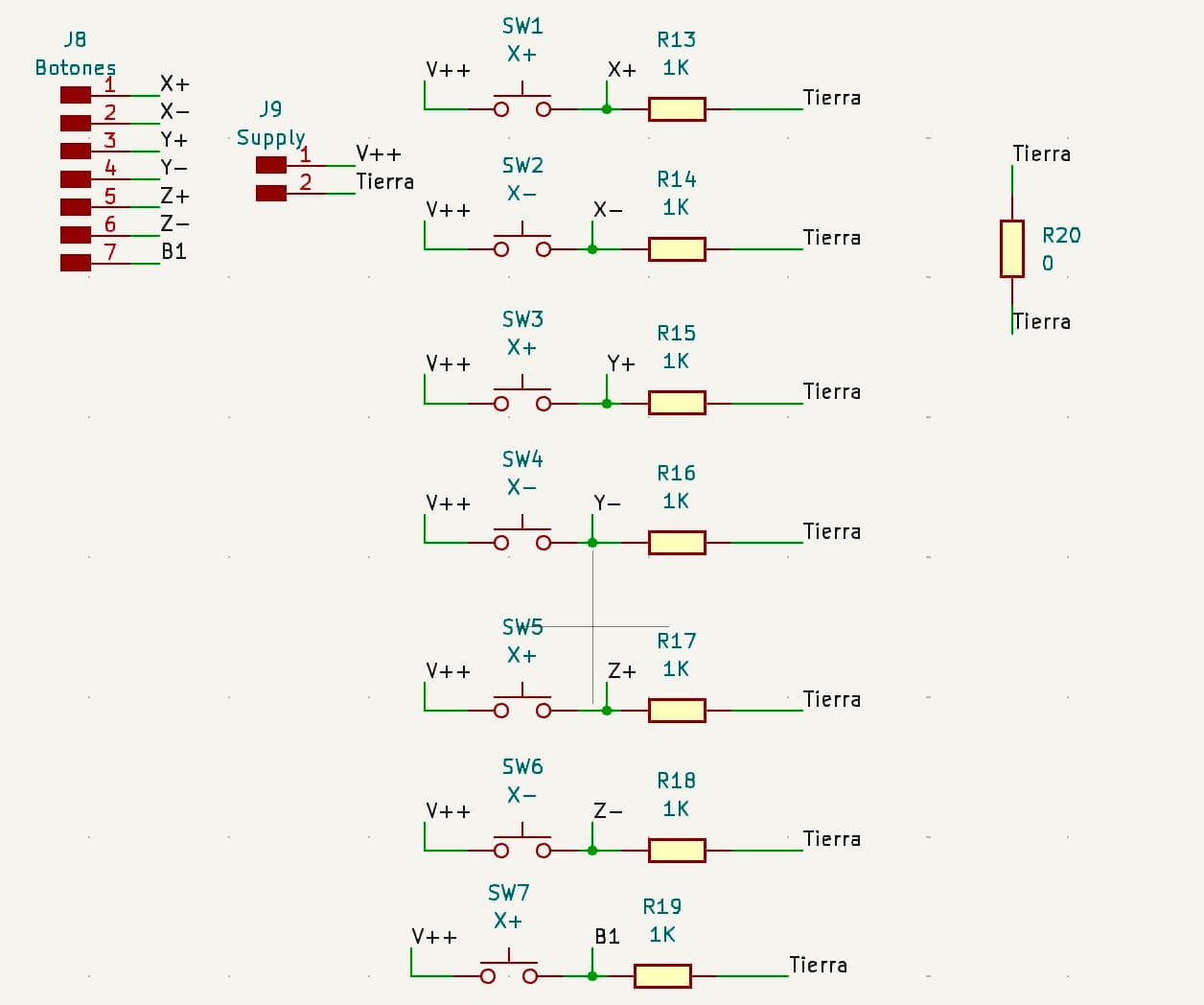
The circuit was designed in KiCad, generating the traces, pads, and labels needed for fabrication.
Gerber files were exported from KiCad and prepared for use with the Monofab, selecting the correct milling and engraving layers. Separate files were generated for the traces, outline, and holes to ensure accurate processing.
Positioning the copper board on the Monofab and adjusting the milling tools. The zero point was calibrated by carefully lowering the tool to the board surface, ensuring precision before starting the milling job.
Starting the milling process for the traces. The machine followed the generated toolpaths, removing the copper layer to leave the desired connections.
Midway view of the milling process on the Monofab. At this stage, the traces were partially visible, and the engraving depth was verified to avoid damaging the board.
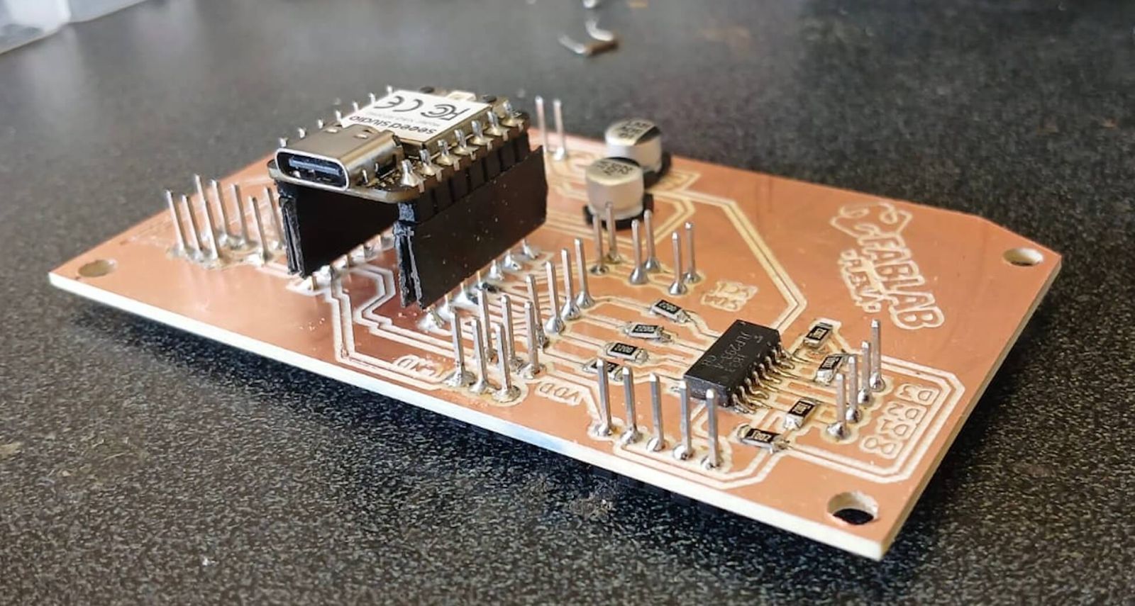
Completion of the milling process for traces and pads on the PCB. After milling, the board was cleaned to remove dust and debris, ensuring clean contact surfaces for soldering.
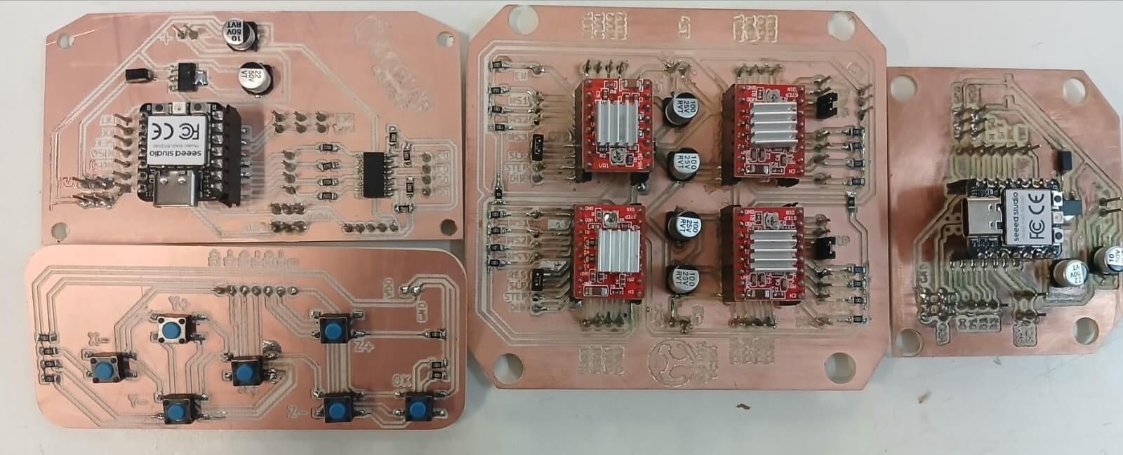
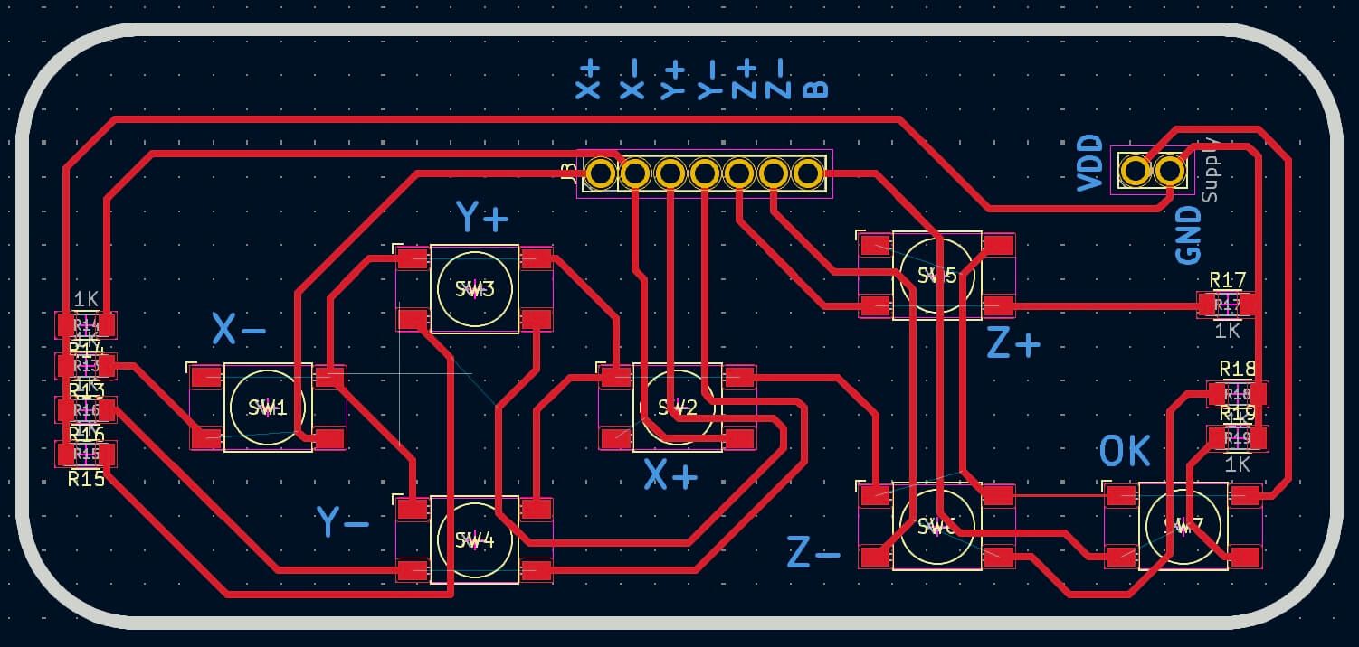
View of the fully milled PCB, ready for component soldering. All traces, pads, and labels were confirmed against the original design before proceeding.
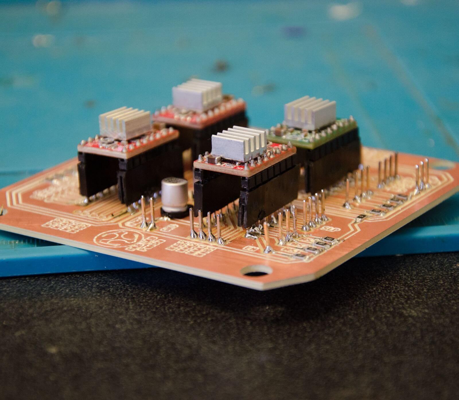
Final result of the PCB, with the circuit traces clearly defined on the board. The next step was to solder the electronic components and perform initial testing to verify correct operation.
The video demonstrates the completed electronics functioning with the CNC system, where the ESP32 microcontroller coordinates the stepper motors and servo movements as programmed.
Programming
The firmware was built on the Grbl ESP32 library, customized for our specific hardware setup. We used Arduino to control the movement of the machine through three red stepper drivers and the Xiao ESP32C3. The firmware takes G-code commands and translates them to stepper driver signals via the ESP32C3, which controls the motion of the X, Y, and Z axes.
The code defines the pins for controlling the stepper motors on each axis (X, Y, and Z). In the setup function, these pins are set to OUTPUT. In the loop function, the direction and stepping of each motor are controlled by sending high and low signals to the respective pins. A delay is used to control the speed of the stepper motors, with the number of steps per revolution set to 600. This results in precise movement and smooth drawing.
Here's the code used for controlling the stepper motors:
See the Pen Untitled by Paula Rivero (@Paula-Rivero) on CodePen.
Below is a video showing the CNC working with the motors and the movement of the X, Y, and Z axes in action. This demonstration highlights the functionality of the system as it performs coordinated movements.
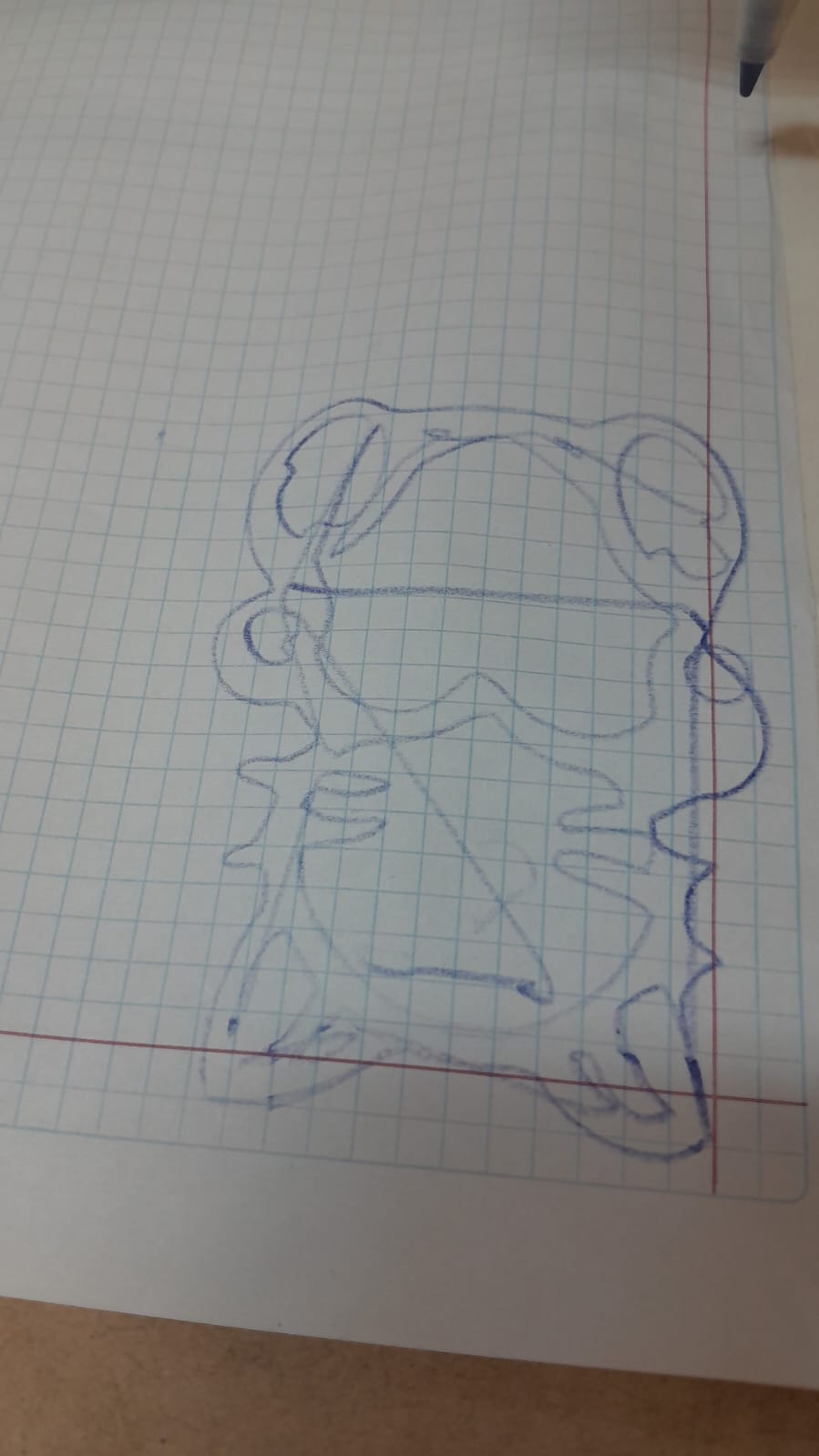
CNC Test with Cat Drawing
To test if the CNC was working and could follow G-code, we used a cute image of a cat with a heart that we found online. This was the result:
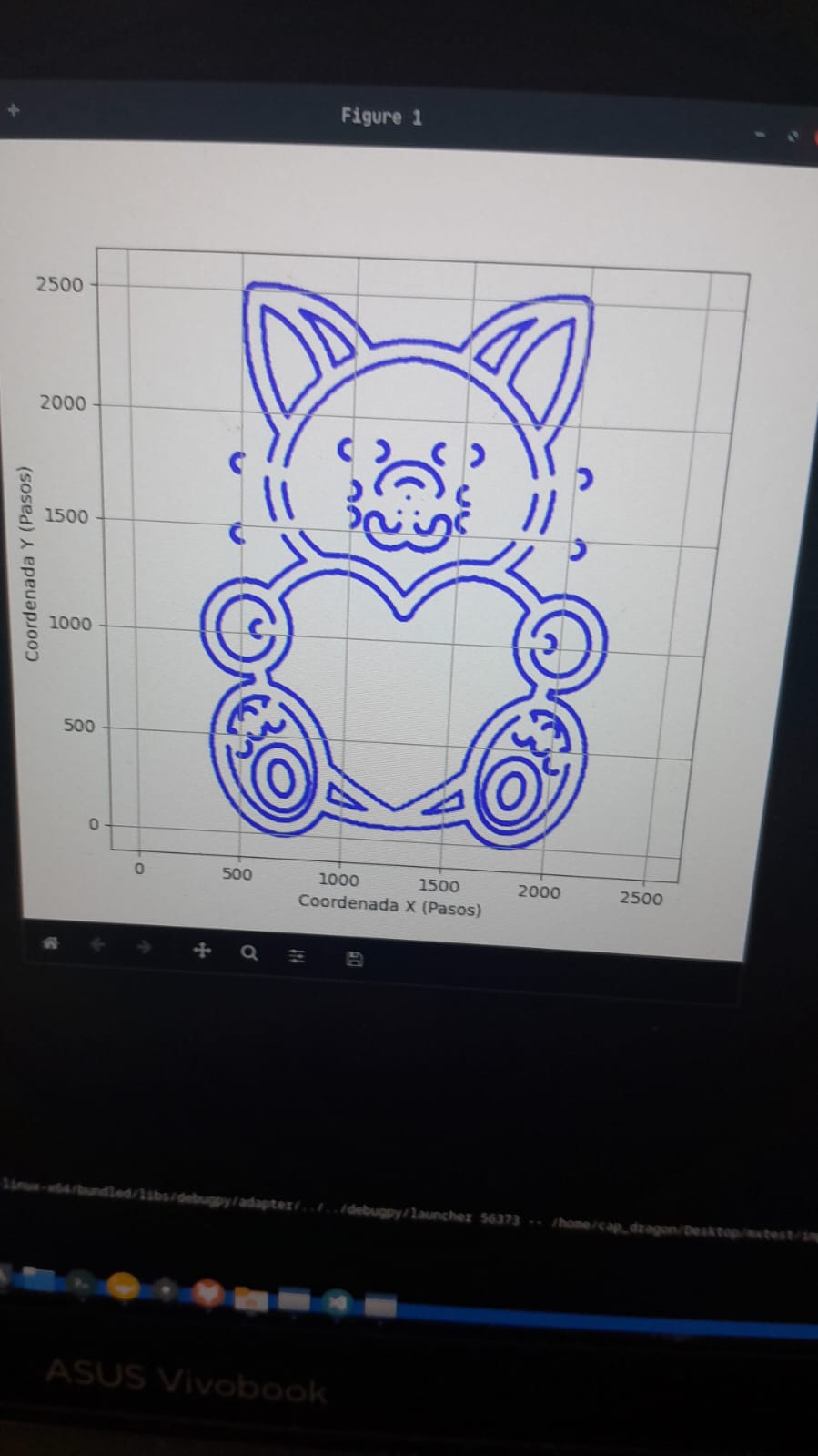
Then we made the necessary adjustments, and the cat was traced like this:
Finally, here's a video of the CNC working:vv
Below is a video showing our CNC Drawing Machine in action:
Acknowledgements
We would like to express our sincere thanks to Maximo A. Figueroa-Navarro and Engineer Gerardo for their valuable collaboration and guidance during the CNC development. Their support and willingness to help us whenever we had questions were key to moving forward with confidence.
We also want to thank our FabLab teammate, José Ángel Zárate, for being there to help us solve several technical issues along the way. His contributions were essential to the success of this project.
We are truly grateful to be part of such a collaborative and supportive environment.
Here is Maximo's research page:
Maximo A. Figueroa-Navarro
Research PageNext Steps
The CNC is working correctly, however, there are several areas of opportunity that can be worked on to optimize the overall system.
Electronics
Although the electronics worked correctly, it would be interesting to redesign the driver board (A4988), placing an “LM555 Timer” in astable form which generates a square signal with a “duty cycle” of 50% with a fixed period that can be connected to the “step” of the A4988 to test stepper motors or drivers without the need of having a controller. As it will not always be necessary to use the “555” a good alternative would be to make the design with a “jumper” that allows energizing or not the integrated according to our needs.
A control was designed to be able to place the origin at “x”, “y” and “z”, however, this was not implemented due to lack of time. This control should be included along with a casing to make its use more comfortable.
Mechanics
The mechanical structure was the most difficult to design due to a lack of experience, as it was the first time for everyone designing a CNC, this led to many technical errors. Listed below are the most important aspects that were determined as areas for improvement in the physical design.
- Z-axis height: The height was not properly considered, so when placing the pencil, it was too far from the bed. Therefore, the z height of the structure must be redesigned or made adjustable.
- Pencil Holder: Due to the height, it was necessary to place a pencil instead of a marker as planned, so the prisoners couldn't hold the pen properly and it moved with the movement. While the z-axis is the problem, different bases could be designed to hold different types of pens or tools.
- Dimensions: The structure is too large for the purpose of drawing, so it would be good to reduce the work area.
- Material: The entire structure was made from MDF, however, an implementation using an aluminum profile with the appropriate bearings and pillow blocks would be more convenient.
- Limit switches: Due to lack of time, the planned limit switches were not installed, so they must be included in a future design.