 ████     █████          ██████   ██████                    █████       ███                         ██████████                     ███
░░███   ███░░░███       ░░██████ ██████                    ░░███       ░░░                         ░░███░░░░███                   ░░░
 ░███  ███   ░░███       ░███░█████░███   ██████    ██████  ░███████   ████  ████████    ██████     ░███   ░░███  ██████   █████  ████   ███████ ████████
 ░███ ░███    ░███       ░███░░███ ░███  ░░░░░███  ███░░███ ░███░░███ ░░███ ░░███░░███  ███░░███    ░███    ░███ ███░░███ ███░░  ░░███  ███░░███░░███░░███
 ░███ ░███    ░███       ░███ ░░░  ░███   ███████ ░███ ░░░  ░███ ░███  ░███  ░███ ░███ ░███████     ░███    ░███░███████ ░░█████  ░███ ░███ ░███ ░███ ░███
 ░███ ░░███   ███        ░███      ░███  ███░░███ ░███  ███ ░███ ░███  ░███  ░███ ░███ ░███░░░      ░███    ███ ░███░░░   ░░░░███ ░███ ░███ ░███ ░███ ░███
 █████ ░░░█████░   ██    █████     █████░░████████░░██████  ████ █████ █████ ████ █████░░██████     ██████████  ░░██████  ██████  █████░░███████ ████ █████
░░░░░    ░░░░░░   ░░    ░░░░░     ░░░░░  ░░░░░░░░  ░░░░░░  ░░░░ ░░░░░ ░░░░░ ░░░░ ░░░░░  ░░░░░░     ░░░░░░░░░░    ░░░░░░  ░░░░░░  ░░░░░  ░░░░░███░░░░ ░░░░░
                                                                                                                                        ███ ░███
                                                                                                                                       ░░██████
                                                                                                                                        ░░░░░░
Mechanical Design + Machine Design
Group Assignment
Task: Design a machine that includes a mechanism, actuation, automation, and application. Build the mechanical parts and operate it manually.
We designed a machine which performs the task of drawing on paper as a pen plotter
- Mechanism: [e.g., timing belts, gears, lead screws]
- Actuation: [e.g., stepper motors]
- Automation: [manual at this stage]
- Application: [e.g., educational tool, prototype drawing machine, etc.]
3-Axis CNC Plotter Group Project
During this week, my team and I decided to design a 3-axis CNC plotter as a group project. It was a very interesting and complex challenge, as it involved the integration of different areas—specifically mechanics, electronics, and programming. Although my main contribution was in the programming part, I also gave feedback and suggestions regarding the mechanical design and did a bit of soldering.
At first, we planned to use an ESP32-WROOM-32 board, so we selected FluidNC (GitHub - bdring/FluidNC) as the firmware, which is specifically adapted for that microcontroller. However, due to changes in the electronics—mainly related to an input we wanted to implement (Input C) and because one of the microcontroller’s pins was damaged—we had to switch to using a XIAO ESP32-C3.
In theory, one would think there's a variant of the firmware compatible with this board, but we discovered that none exists. I then started researching how to adapt it, but the differences between the dual-core architecture of the ESP32-WROOM and the single-core XIAO ESP32-C3 made it impossible to implement several functions correctly. I spent a day and a half trying to adapt the firmware, but in the end, I realized I wouldn't have enough time to make it work decently.
I informed Professor Osorio and my team about the issue, and due to the delivery deadline approaching, we decided to design a new board using the ESP32 to give us more flexibility in case of any issues. However, due to time pressure and uncertainty about whether the board would work properly, we ultimately decided to program everything from scratch.
I then developed the following key codes for our plotter:
- Test code (c++/arduino)
// Eje X
  const int dirPin0 = D0;
  const int stepPin0 = D1;
  // Eje Y
  const int dirPin1 = D2;
  const int stepPin1 = D3;
  // Eje Z
  const int dirPin2 = D8;
  const int stepPin2 = D7;


  const int stepsPerRevolution = 600;

  void setup() {
    pinMode(dirPin0, OUTPUT);
    pinMode(stepPin0, OUTPUT);
    pinMode(dirPin1, OUTPUT);
    pinMode(stepPin1, OUTPUT);
    pinMode(dirPin2, OUTPUT);
    pinMode(stepPin2, OUTPUT);
  }

  void loop() {

    // digitalWrite(dirPin0, HIGH);
    // digitalWrite(dirPin1, HIGH);
    // digitalWrite(dirPin2, HIGH);
    digitalWrite(dirPin0, LOW);
    digitalWrite(dirPin1, LOW);
    digitalWrite(dirPin2, LOW);

    for (int i = 0; i < stepsPerRevolution; i++) {
      digitalWrite(stepPin0, HIGH);
  digitalWrite(stepPin1, HIGH);
  digitalWrite(stepPin2, HIGH);
  delayMicroseconds(800);
  digitalWrite(stepPin0, LOW);
  digitalWrite(stepPin1, LOW);
  digitalWrite(stepPin2, LOW);
  delayMicroseconds(800);
    }

      delay(1000);
      digitalWrite(dirPin0, LOW);
    digitalWrite(dirPin1, LOW);
    digitalWrite(dirPin2, LOW);
    for (int i = 0; i < stepsPerRevolution; i++) {
    digitalWrite(stepPin0, HIGH);
  digitalWrite(stepPin1, HIGH);
  digitalWrite(stepPin2, HIGH);
  delayMicroseconds(800);
  digitalWrite(stepPin0, LOW);
  digitalWrite(stepPin1, LOW);
  digitalWrite(stepPin2, LOW);
  delayMicroseconds(800);
    }

    delay(1000);

}# Import the matplotlib library for plotting
import matplotlib.pyplot as plt
# Import the regular expressions library for pattern matching
import re
# Import math for mathematical constants and functions
import math
# Function to calculate the steps-to-mm conversion factor based on the pulley diameter and steps per revolution
def calculate_conversion_factor(diameter_external_mm, steps_per_revolution):
avance_por_giro = math.pi * diameter_external_mm # Distance moved per revolution (circumference)
conversion_factor = steps_per_revolution / avance_por_giro # Steps per mm
return conversion_factor
# Function to process a G-code file and convert X, Y coordinates in mm to steps
def process_gcode(file_path, output_path, conversion_factor, max_mm=300):
x_coords = []
y_coords = []
# Read the input G-code file
with open(file_path, 'r') as file:
lines = file.readlines()
# Open the output file to write absolute position G-code in steps
with open(output_path, 'w') as output_file:
output_file.write("%\n") # G-code start delimiter
for line in lines:
# Search for lines containing both X and Y coordinates
match = re.search(r'X(-?\d+(\.\d+)?)\s+Y(-?\d+(\.\d+)?)', line)
if match:
x_mm = float(match.group(1)) # Extract X in mm
y_mm = float(match.group(3)) # Extract Y in mm
# Skip coordinates that exceed maximum allowed mm
if abs(x_mm) > max_mm or abs(y_mm) > max_mm:
continue
# Convert mm to motor steps
x_steps = round(x_mm * conversion_factor)
y_steps = round(y_mm * conversion_factor)
# Save to coordinate lists for plotting
x_coords.append(x_steps)
y_coords.append(y_steps)
# Write the converted steps to the output G-code file
output_file.write(f"X{x_steps} Y{y_steps}\\n\n") # Note: \\n is a literal, then a real newline
output_file.write("\n%\n") # G-code end delimiter
return x_coords, y_coords # Return the coordinate lists
# Function to convert absolute position G-code to relative movement G-code
def generate_relative_gcode(input_path, relative_output_path):
prev_x = 0
prev_y = 0
# Open the input file (absolute steps) and the output file (relative steps)
with open(input_path, 'r') as infile, open(relative_output_path, 'w') as outfile:
outfile.write("%\n") # G-code start delimiter
for line in infile:
# Match lines with X and Y steps
match = re.match(r'X(-?\d+)\s+Y(-?\d+)', line)
if match:
x = int(match.group(1)) # Current absolute X
y = int(match.group(2)) # Current absolute Y
dx = x - prev_x # Calculate relative X
dy = y - prev_y # Calculate relative Y
outfile.write(f"X{dx} Y{dy}\\n\n") # Write relative steps with literal newline
prev_x = x # Update previous X
prev_y = y # Update previous Y
outfile.write("\n%\n") # G-code end delimiter
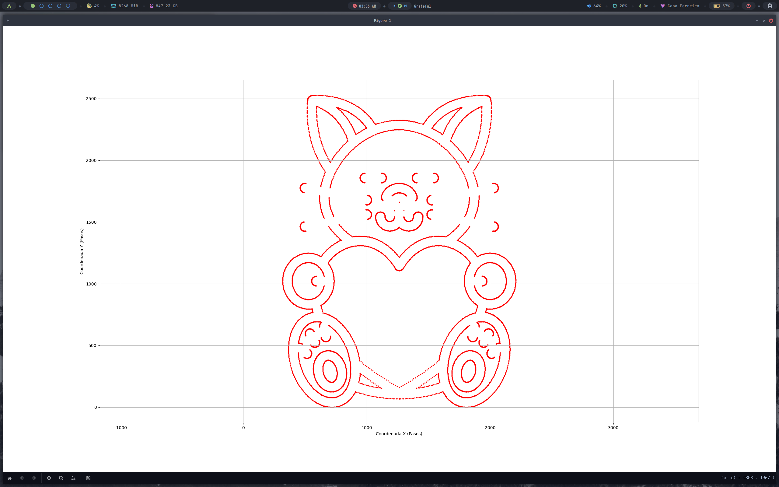
# Function to plot the G-code path using the step coordinates
def plot_coordinates(x_coords, y_coords):
plt.figure(figsize=(6, 6))
plt.scatter(x_coords, y_coords, color='r', s=3) # Small red dots for each point
plt.xlabel('X Coordinate (Steps)')
plt.ylabel('Y Coordinate (Steps)')
plt.grid(True)
plt.axis('equal') # Keep aspect ratio equal for X and Y
plt.show()
# -------------------- CONFIGURATION
# Define the pulley diameter and the number of steps per revolution for the motor
diameter_external_mm = 16
steps_per_revolution = 600
# Calculate the mm to steps conversion factor
conversion_factor = calculate_conversion_factor(diameter_external_mm, steps_per_revolution)
# File paths for input G-code and output step-based G-code
input_file = 'Initial_G_code.txt'
absolute_output = 'absolute_gcode_steps.txt'
relative_output = 'relative_gcode_steps.txt'
# Process G-code: convert mm to steps and save absolute coordinates
x_coords, y_coords = process_gcode(input_file, absolute_output, conversion_factor)
# Convert absolute G-code to relative movement G-code
generate_relative_gcode(absolute_output, relative_output)
# Plot the converted path
plot_coordinates(x_coords, y_coords)
  import serial
  import time

  # Define the serial port and baud rate for communication
  PORT = '/dev/ttyACM0'
  BAUD_RATE = 115200

  # Path to the file that contains the G-code converted to steps
  TXT_FILE = 'absolute_gcode_steps.txt'

  # Wait 2 seconds to give the device time to initialize
  time.sleep(2)

  try:
      # Try to establish a serial connection
      ser = serial.Serial(PORT, BAUD_RATE, timeout=2)
      print(f"Connected to {PORT} at {BAUD_RATE} baud")
  except serial.SerialException:
      # If the connection fails, print an error and exit
      print(f"Error connecting to port {PORT}")
      exit()

  # Open the file that contains the G-code steps
  with open(TXT_FILE, 'r') as file:
      for line in file:
          # Remove any leading/trailing whitespace characters
          line = line.strip()

          # Skip empty lines, comment markers (%), and specific lines with 'S0:'
          if not line or line.startswith('%') or 'S0:' in line:
              continue

          # Print the line to be sent
          print(f"Sending: {line}")

          # Send the line over the serial connection, adding a newline character
          ser.write((line + '\n').encode())

          # Initialize a variable to store the response and set a timeout limit (1 second)
          response = ""
          timeout = time.time() + 1  # Wait up to 1 second for a response

          while True:
              # If there is incoming data from the serial port, read and decode it
              if ser.in_waiting > 0:
                  response += ser.read(ser.in_waiting).decode()

                  # Check if the response contains 'ok' (case-insensitive)
                  if 'ok' in response.lower():
                      print("Received: ok\n")
                      break

              # If the timeout limit is reached and no 'ok' was received, break the loop
              if time.time() > timeout:
                  print("Timeout. 'ok' not received.\n")
                  break

  # Close the serial connection
  ser.close()
  print("Instruction sending finished.")
#include

        // Define the direction and step pins for each axis
        #define dirPinX D0
        #define stepPinX D1
        #define dirPinY D2
        #define stepPinY D3
        #define dirPinZ D8
        #define stepPinZ D7

        // Create AccelStepper objects for each axis
        AccelStepper stepperX(AccelStepper::DRIVER, stepPinX, dirPinX);
        AccelStepper stepperY(AccelStepper::DRIVER, stepPinY, dirPinY);
        // Z axis is defined but not used in this version
        AccelStepper stepperZ(AccelStepper::DRIVER, stepPinZ, dirPinZ);

        // Variables to store current absolute position
        long currentX = 0;
        long currentY = 0;

        // Movement speed in steps/second
        const float speed = 600.0;

        // Variable to store incoming serial data
        String serialLine = "";

        void setup() {
          Serial.begin(115200);         // Start serial communication
          while (!Serial);              // Wait for serial port to be ready

          // Set maximum speed and acceleration for X and Y axes
          stepperX.setMaxSpeed(speed);
          stepperY.setMaxSpeed(speed);
          stepperX.setSpeed(0);
          stepperY.setSpeed(0);

          stepperX.setAcceleration(100);
          stepperY.setAcceleration(100);

          // Notify host that the controller is ready
          Serial.println("ok");
        }

        // This function handles motion from the current to the target position
        void processMove(long targetX, long targetY) {
          // Calculate the difference between current and target positions
          long deltaX = targetX - currentX;
          long deltaY = targetY - currentY;

          // Calculate total distance
          long distance = sqrt(deltaX * deltaX + deltaY * deltaY);
          if (distance == 0) return; // Skip if there's no movement

          // Calculate movement proportions for each axis
          float proportionX = abs(deltaX) / (float)distance;
          float proportionY = abs(deltaY) / (float)distance;

          // Set speeds in proportion to movement direction
          stepperX.setSpeed(speed * (deltaX > 0 ? 1 : -1) * proportionX);
          stepperY.setSpeed(speed * (deltaY > 0 ? 1 : -1) * proportionY);

          // Total number of steps to move
          long stepsX = abs(deltaX);
          long stepsY = abs(deltaY);
          long stepsDoneX = 0;
          long stepsDoneY = 0;

          // Move both motors proportionally until reaching the target
          while (stepsDoneX < stepsX || stepsDoneY < stepsY) {
            if (stepsDoneX < stepsX && stepperX.runSpeed()) stepsDoneX++;
            if (stepsDoneY < stepsY && stepperY.runSpeed()) stepsDoneY++;
          }

          // Update current position
          currentX = targetX;
          currentY = targetY;
        }

        void loop() {
          // Read characters from serial until newline is received
          while (Serial.available()) {
            char c = Serial.read();
            if (c == '\n') {
              serialLine.trim();  // Remove whitespace

              // Parse command if it starts with 'X'
              if (serialLine.startsWith("X")) {
                int xIndex = serialLine.indexOf('X');
                int yIndex = serialLine.indexOf('Y');

                // Extract X and Y values and execute movement
                if (xIndex >= 0 && yIndex > xIndex) {
                  long xVal = serialLine.substring(xIndex + 1, yIndex).toInt();
                  long yVal = serialLine.substring(yIndex + 1).toInt();
                  processMove(xVal, yVal);
                  Serial.println("ok");  // Acknowledge movement completed
                }
              }
              serialLine = "";  // Clear buffer for next command
            } else {
              serialLine += c;  // Append character to input buffer
            }
          }
        }
During the first motor tests, we noticed that the axes were not properly aligned, which prevented correct movement. We informed the mechanical team, who checked the problem that same day. By the next day, it was adjusted and ready to test the real code.
When testing the G-code compiler, communication, and the XIAO code, the Z-axis initially didn’t work as expected. We discovered it hadn’t been correctly designed, and due to the limited remaining time, we had to improvise and temporarily disable it to move forward.
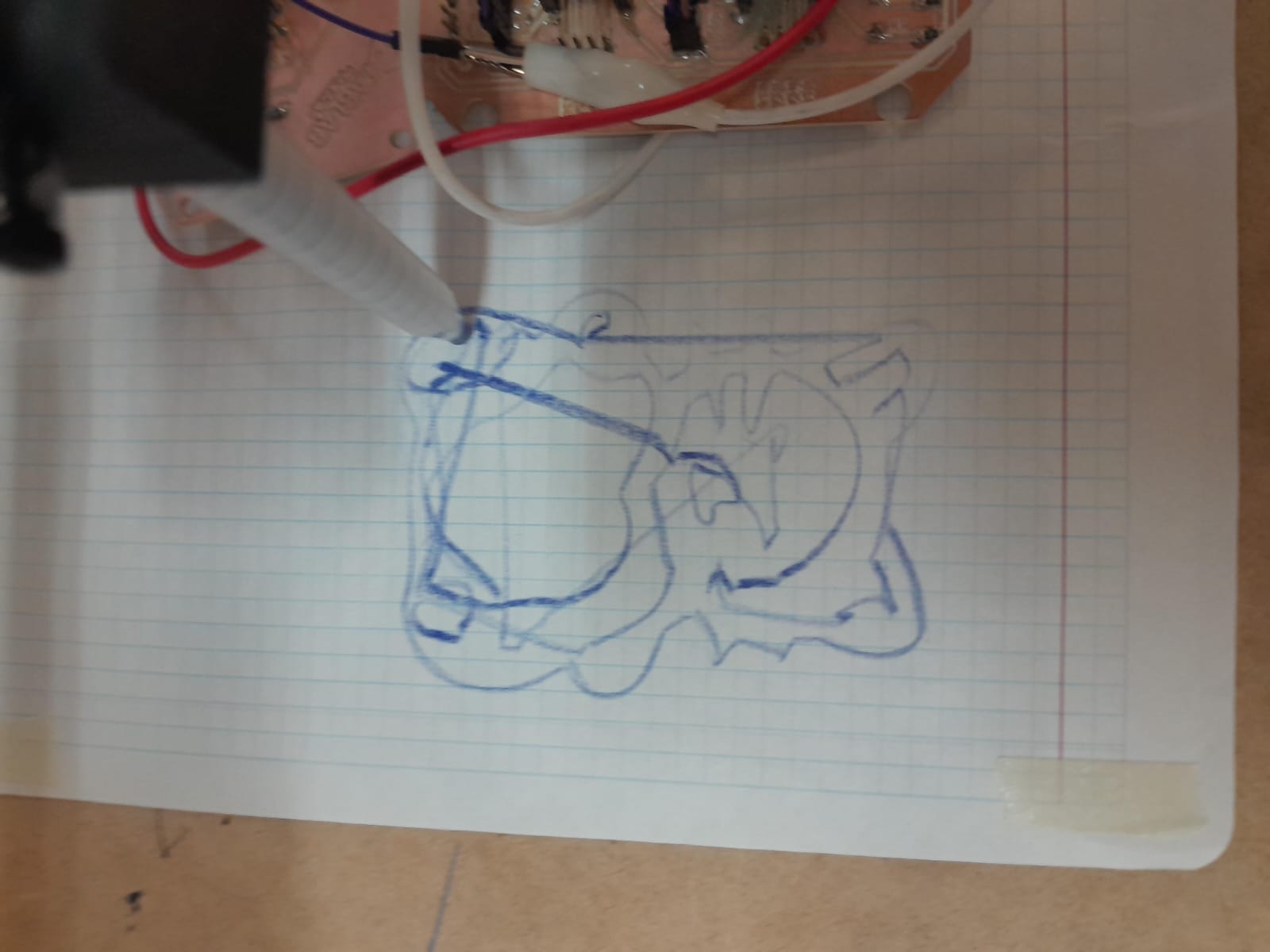
Our first Picasso
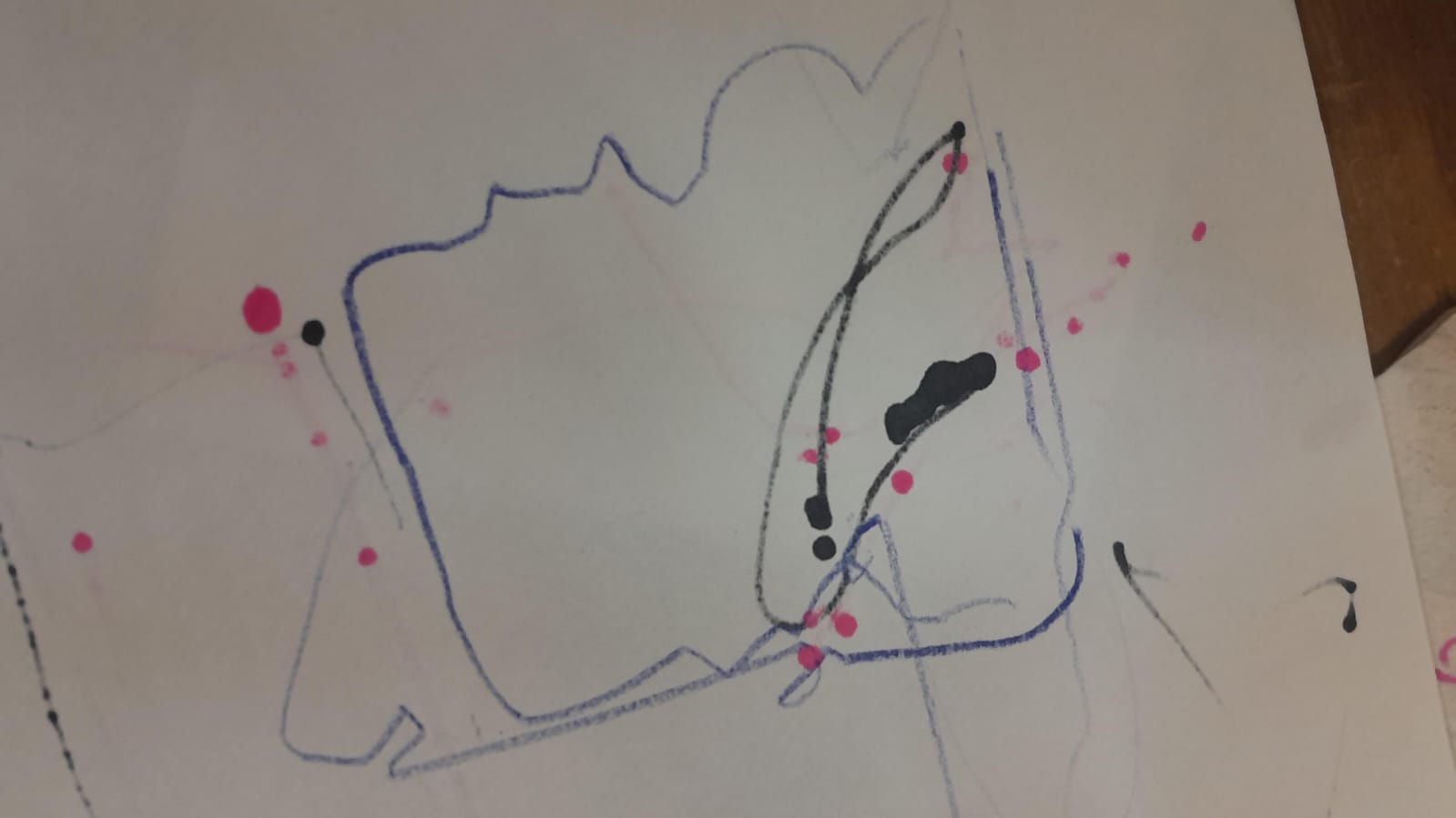
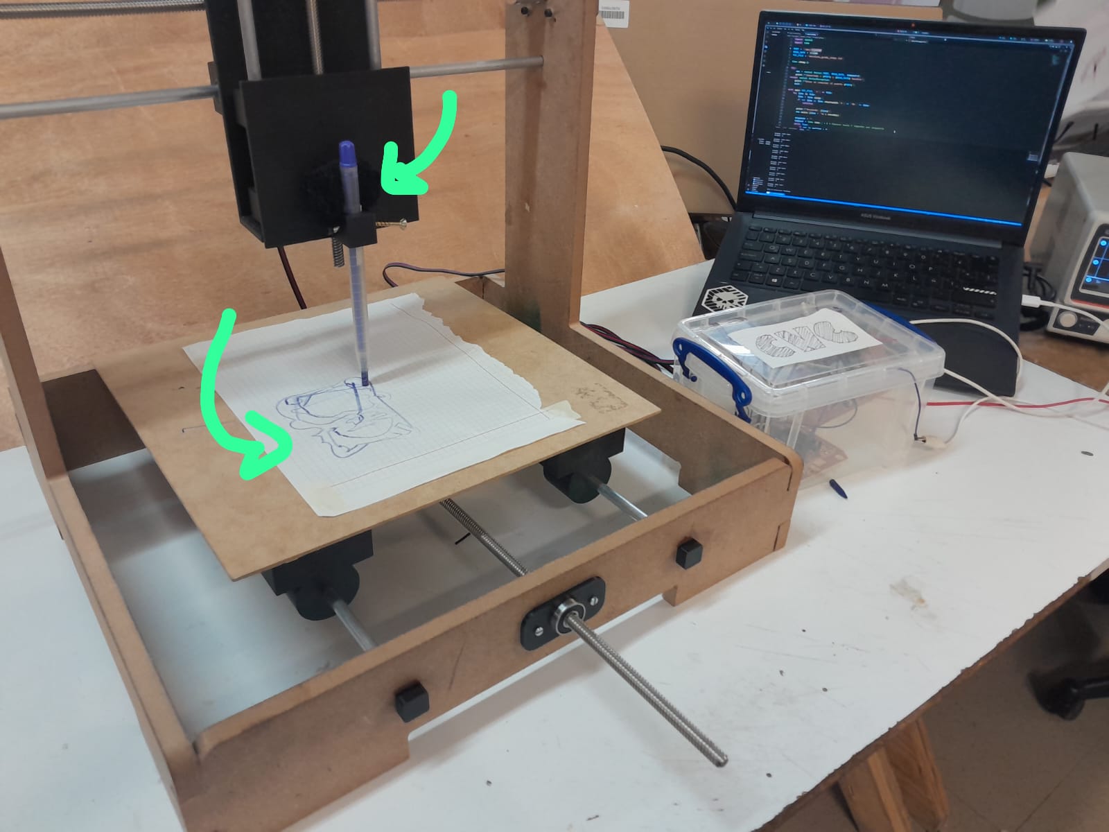
In addition to the Z-axis problem, there was another issue: the pen holder was not firm enough, so it moved while drawing. This affected the drawing accuracy, which was not as good as expected due to that instability.
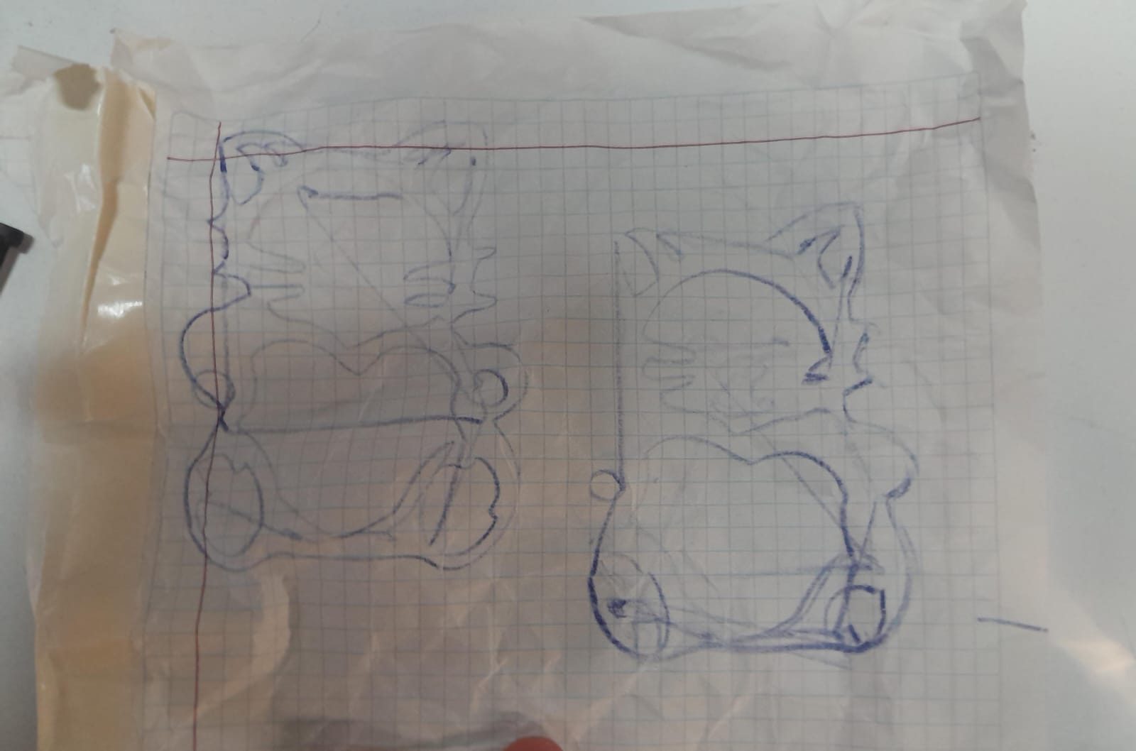
final drawings
 "">
"">
 "">
"">