Week 12:Mechanical design, Machine design
This week, we built a CNC machine whose objective is to take a picture, vectorize the image, and draw it with a fine-tipped pen.
As part of the group project for Fab Academy 2025, we designed and built a CNC machine capable of drawing on paper using a pen mounted on the Z-axis. This drawing CNC uses stepper motors and belts to move in the X and Y directions, and a servo to lift and lower the pen. The project required the integration of mechanical design, electronics, and programming to bring the machine to life. Group CNC Teamwork →
What is a CNC?
A CNC (Computer Numerical Control) machine is a device that uses computer commands to control the movement of tools and machinery to perform tasks such as cutting, milling, engraving, and drawing. CNC machines can work in 2 or 3 axes (X, Y, and Z), allowing precise control over the material or tool.
What is Vectorization?
Vectorization is the process of converting a raster image (made of pixels) into a vector image (made of paths). This allows the CNC to follow the paths and reproduce the drawing with high precision.
Examples of Vectorized Drawings:
- Portraits converted to line art
- Logos
- Architectural floor plans
Team Collaboration
This was a team assignment. To complete the CNC, we divided the work among team members. In my case, I was responsible for building the structure of the CNC and ensuring its mechanical movement.
🛠️ Materials List with Prices and Purchase Links
Below is the list of materials used to build the structure of the CNC machine, including estimated prices in USD and purchase links. Note that prices may vary slightly depending on supplier and availability.
| Material | Estimated Price (USD) | Purchase Link |
|---|---|---|
| MDF board 1.3 cm thick (63x122 cm) | $18–$24 | Home Depot (MX) |
| Nema 17 Stepper Motor (x3) | $25 each | impresoras3dpuebla.com |
| Bearing blocks (x2) | $6–$12 each | MercadoLibre |
| Bearings (x6) | $4.30 each | impresoras3dpuebla.com |
| T8 lead screw nut (x2) | $7.50 each | MercadoLibre |
| Aluminum tube 5/16” (3 m) | $15 total | Amazon |
| Lead screw 50 cm (x2) | $18.50 each | Amazon MX |
| Flexible couplers (x3) | $0.60 each | olvera.com |
| M3 screws (pack of 100) | $8–$10 | MercadoLibre |
| M3 bearings (for better fit) | $9 per pack | MercadoLibre |
Note: Prices are estimates based on online sources and may change. Be sure to verify shipping and availability when purchasing.
Initial Sketch
I started by sketching the structure on paper. I decided the machine would have two rails for movement and a central lead screw for X, Y, and Z motion — since it's a 3-axis CNC. I also chose a work area of 40 x 40 cm to fit an A4 sheet (210 x 297 mm) comfortably for drawing.
Structure Design and CNC Cutting
To design the structure (40x40 cm), I used SolidWorks, a CAD software that requires a paid license. You can download the software through this link: https://www.solidworks.com/es
Basic SolidWorks Commands Used:
| Command | Description |
|---|---|
| Sketch | Create 2D sketches on planes |
| Smart Dimension | Define measurements and constraints |
| Center Rectangle | Draw rectangles from the center point |
| Circle | Create a circle by selecting its center and radius |
| Fillet | Round edges between two lines |
| Trim Entities | Cut unnecessary lines from a sketch |
| Extruded Boss/Base | Create 3D shapes from 2D sketches |
| Extruded Cut | Remove material from a 3D object |
Design Process in SolidWorks
Before anything else, I used SolidWorks in centimeters, as it was easier for me to visualize the measurements this way than in millimeters.
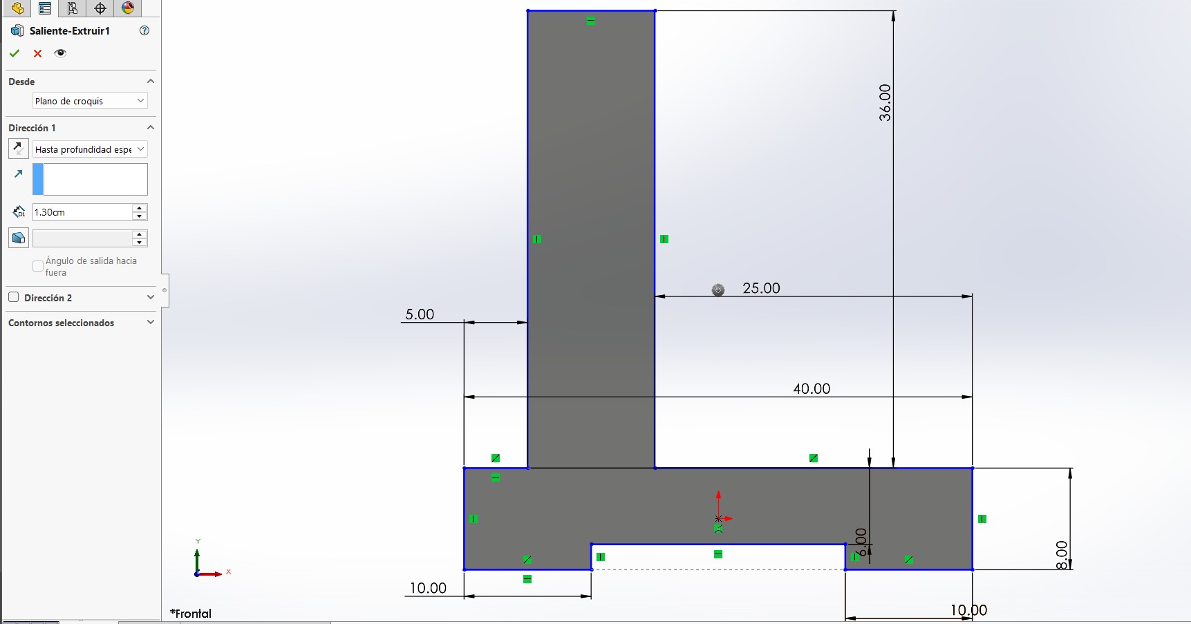
I first created a sketch using the tools Smart Dimension, Center Rectangle, and Trim Entities (Scissors). This shape would become the side panels of the CNC. Then, I extruded the sketch to match the thickness of the material, which is 1.3 cm. I also used the Fillet tool to round the corners and make the design smoother and safer to handle.
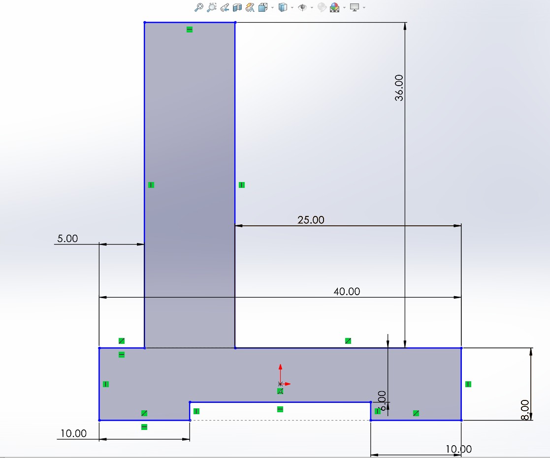
It’s important to remember that each side will contain different components. On one side, there will be a NEMA 17 motor and aluminum guides; on the opposite side, there will be a bearing block (chumacera) with a circular bearing.
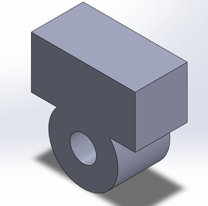
Bearing Block Side
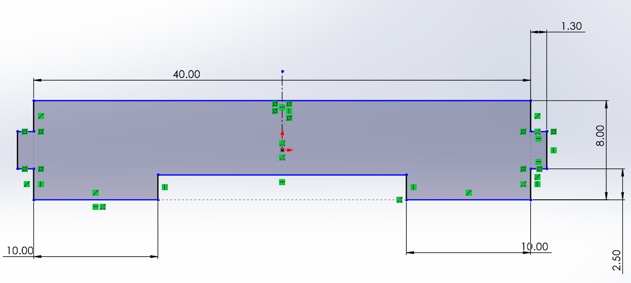
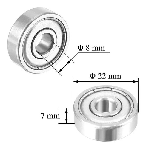
To design this side, I based it on the technical drawing of the KFL-08 bearing block (8 mm).
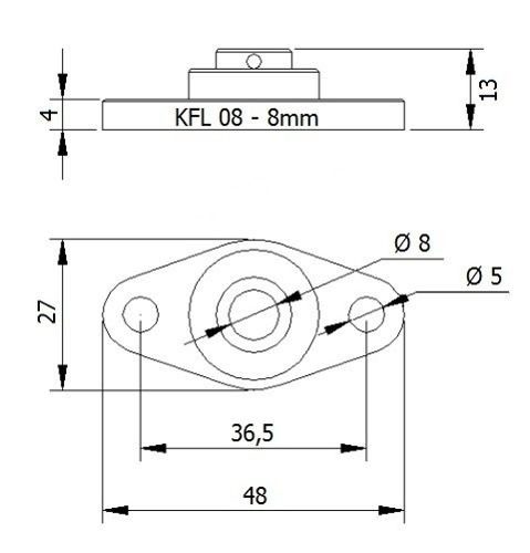
Using this diagram, I created another sketch. I spaced the screw hole and the guide holes 5 cm apart to allow smooth movement and leave enough space for the mechanism. At the bottom, I added the connecting slots where the other pieces will be inserted—also with a thickness of 1.3 cm, matching the material. I then used the Fillet tool to round the external corners, improving the aesthetics and safety of the part.
Finally, I made a cut through the part to finish shaping the side panel.
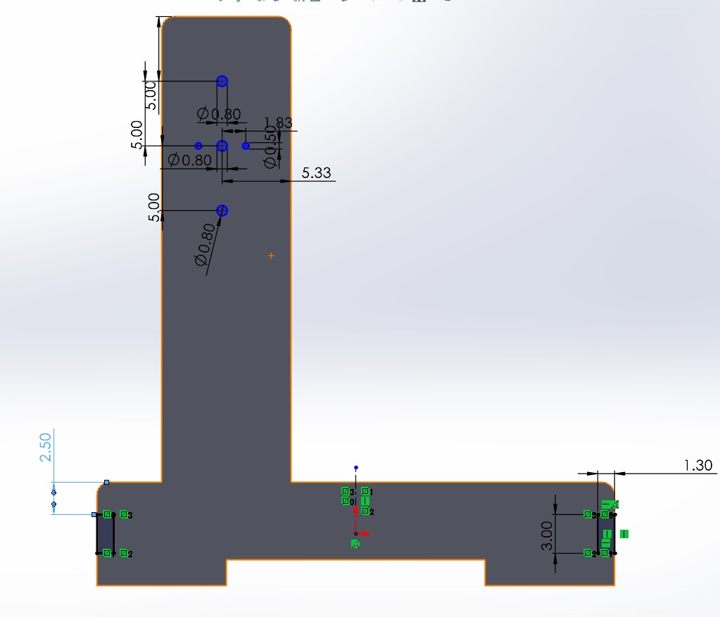
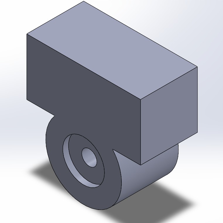
And with that, the bearing block side of the CNC is complete.
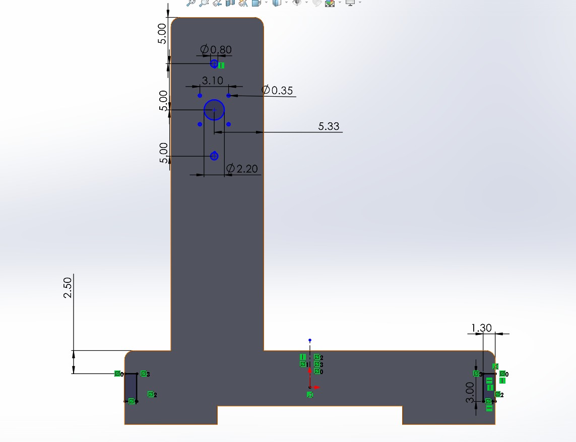
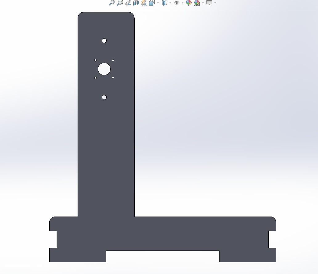
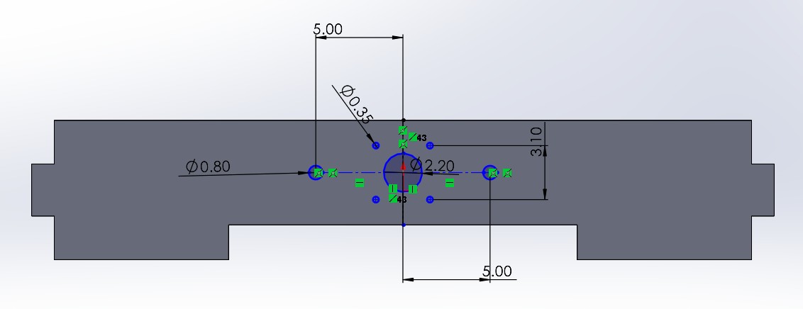
NEMA 17 Motor Side
This side is similar to the bearing block side in shape and structure, but it includes the necessary holes and mounting space for the NEMA 17 stepper motor.
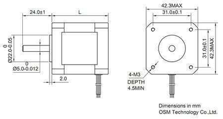
Using the NEMA 17 technical drawing, I created a new sketch in SolidWorks. I placed the motor mount holes at the center, aligned with the guide holes. Just like the other side, I kept 5 cm of separation between the motor hole and the aluminum guide holes to ensure smooth mechanical movement and enough space for the components. At the bottom, I added the notches for connecting to the rest of the CNC structure, with a matching material thickness of 1.3 cm. I also applied the Fillet tool to the corners to match the smooth design of the opposite side.
Once the sketch was complete, I extruded it and finalized the shape with the necessary cuts.
And with that, the NEMA 17 motor side of the CNC is complete.
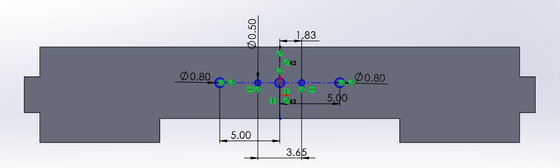
Base Joints
After designing the side panels, I created the other two base joints following the same steps, only adjusting the dimensions to fit their placement in the structure. In this case, instead of cutting holes for tabs, I modeled the tabs themselves to connect with the previous parts. Again, the thickness used was 1.3 cm.
This is the base design for both pieces, as they share the same structural logic and only differ in size and the components they include.
Just like before, each side of the base has a specific function:
- Motor Side (NEMA 17): This piece includes the tabs and holes needed to mount the motor securely.
- Bearing Block Side: This piece features a cutout and holes to fit the KFL-08 bearing block.
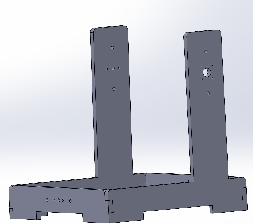
And this is the structure assemble :
Preparing Files in VCarve and CNC Cutting
Once I had all the parts designed in SolidWorks with the correct measurements, I exported them as DXF files to be used in VCarve.
You can download a trial version of VCarve from the official Vectric website:
https://www.vectric.com/products/vcarve
Setting Up in VCarve
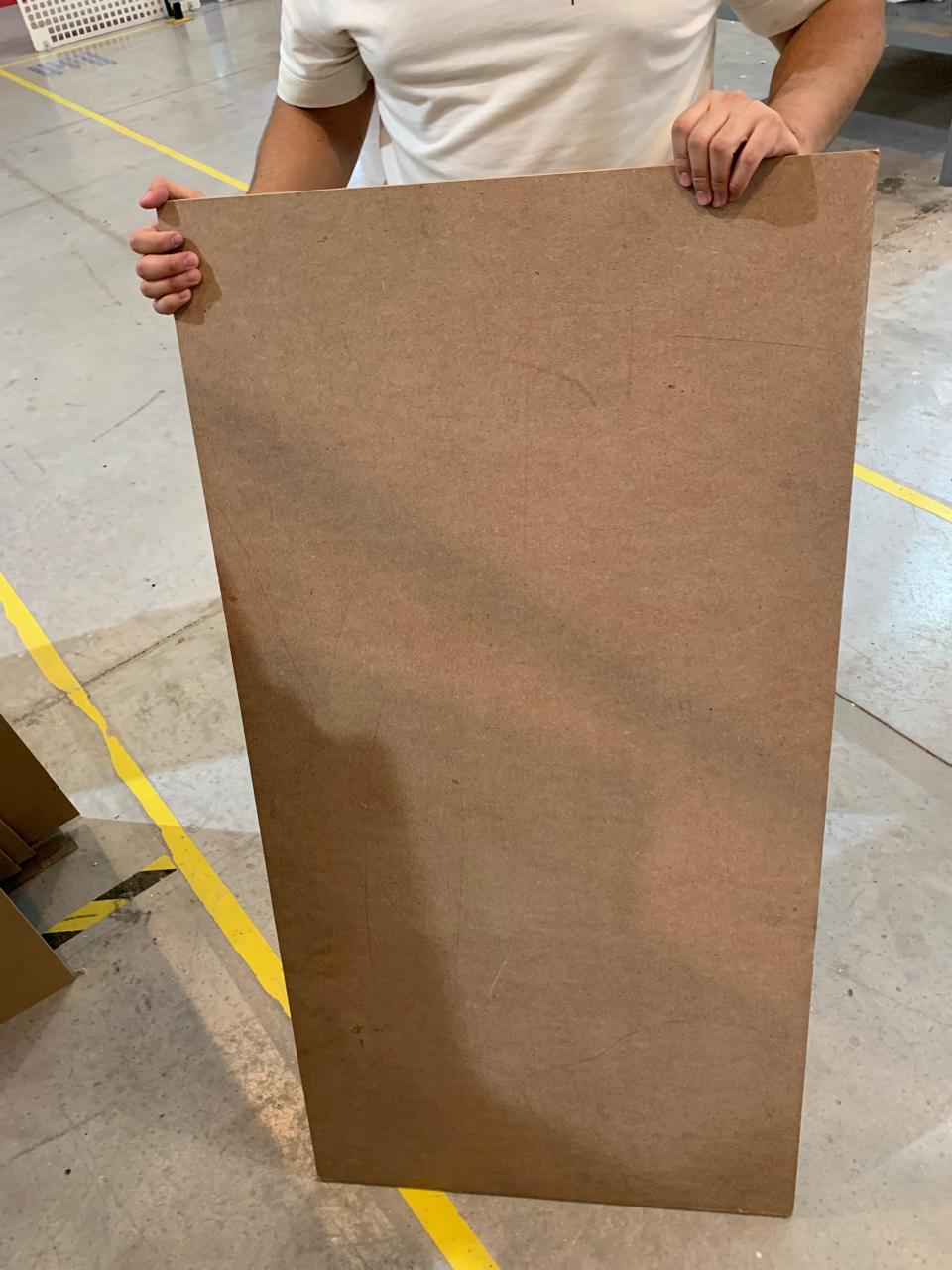
The material we used , MDF, heres a picture of the material we used:
In VCarve, I created a new job with the following settings:
- Job Size: 60 cm x 30 cm
- Material Thickness: 1.3 cm
- Units: Centimeters
- Z Zero Position: Top of the material
I imported the DXF files and arranged the parts to fit within the job area. Then, I set the toolpaths:
- Tool: End Mill 1/8 inch (3.175 mm)
- Cut Depth: 1.4 cm (to ensure it cuts through the material)
- Pass Depth: 0.3 cm
- Feed Rate: 60 mm/s
- Plunge Rate: 30 mm/s
- Toolpath Type: Profile cut (Outside)
I also added tabs to each part to keep them in place during cutting. These tabs were 0.3 cm tall and 0.5 cm long.
Exporting and Machining
Once everything was ready, I calculated the toolpaths and exported the G-code using the post-processor for our CNC machine . I saved the toolpath file as a .sbp file.
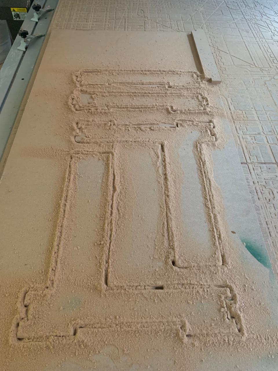
I secured the 1.3 cm material board on the CNC bed using screws on the corners and zeroed the X, Y, and Z axes on the top-left corner of the material.
With everything set, I ran the job and carefully monitored the machine during the entire cutting process.
Post-Processing
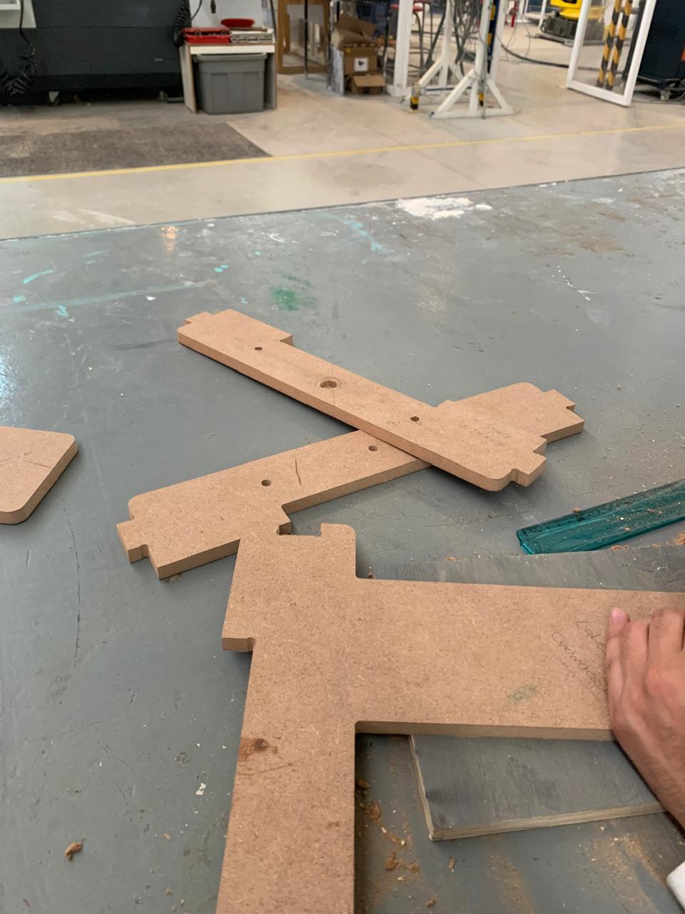
Once the CNC finished cutting, I made sure all joints fit together correctly, and I tested the assembly of the CNC sides and base.
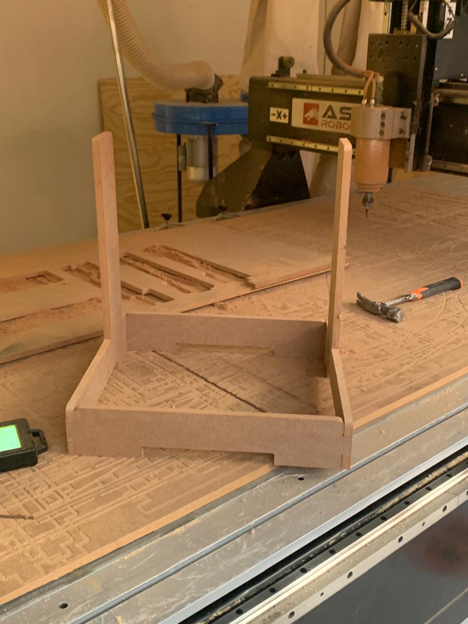
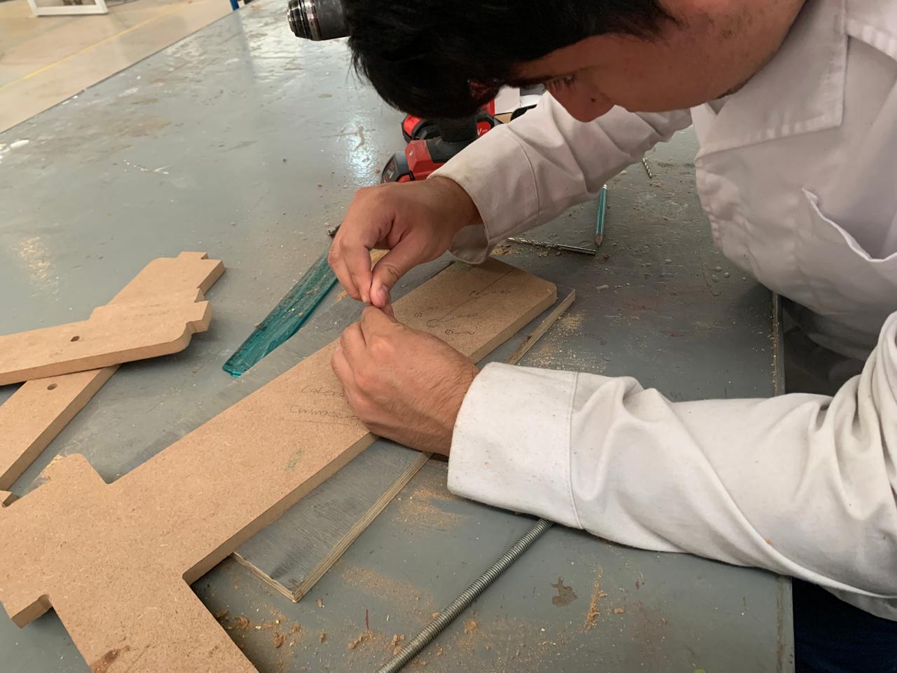
However, the machine did not cut the holes as expected, and due to the fact that my teammate moved the material, we were no longer able to re-align it and cut the holes using the CNC. Because of this, we had to make the holes manually.
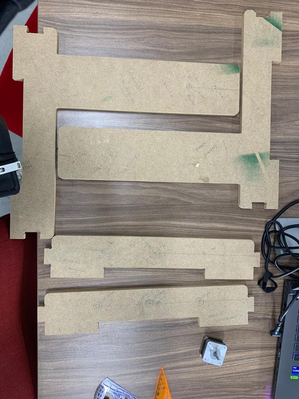
To do this, we used a ruler to measure and mark the positions of the holes, and then used a drill to make them manually.
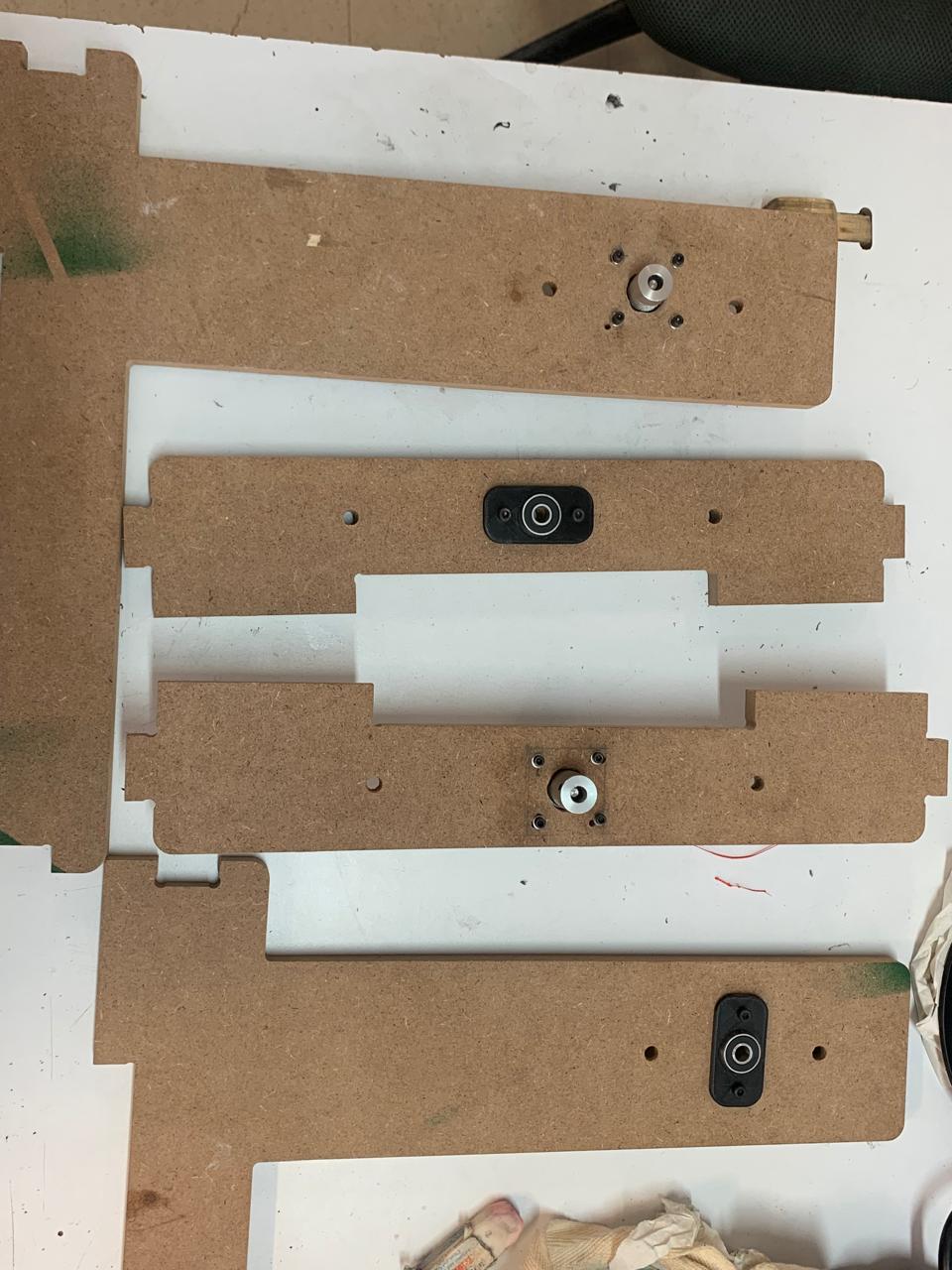
The final result, with the motor and the bearing blocks (chumaceras) installed, looked like this:
Note
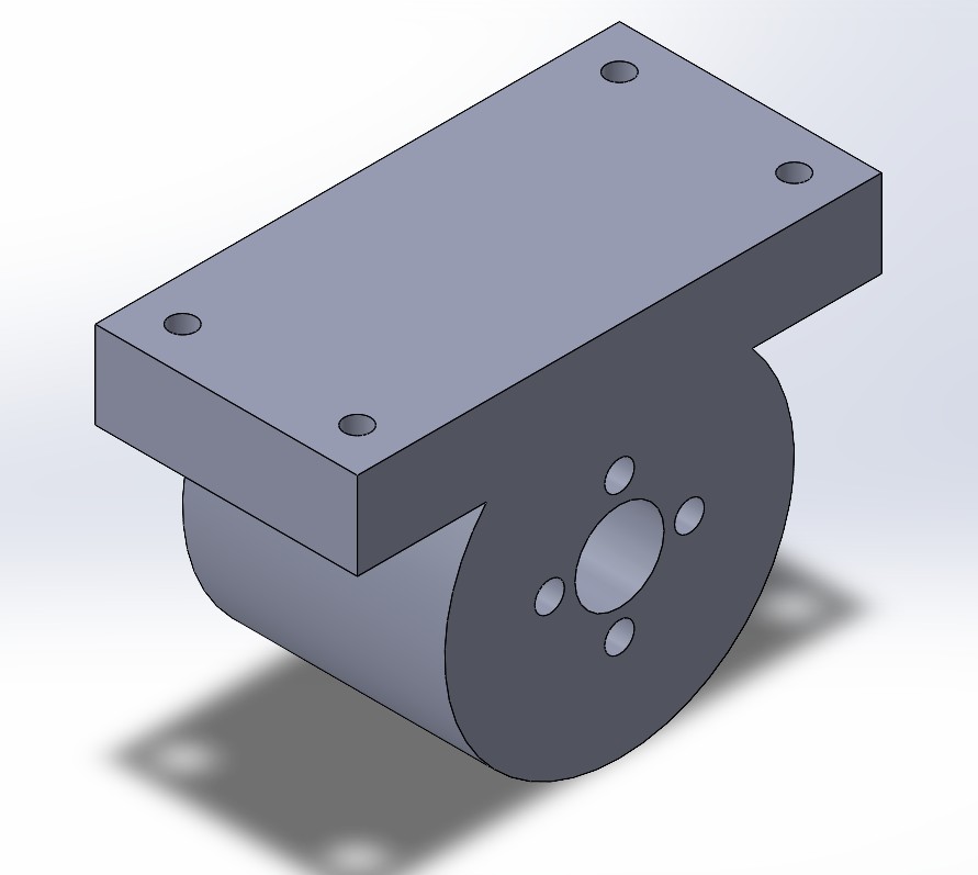
In the end, since there were no KFL-08 bearing blocks available, I had to design one in SolidWorks using the same dimensions and a circular bearing.
Original Design Files and Laser Cutting Files
Below you can find the original design and laser cutting files:
Axis Design in SolidWorks
To better understand and organize the movement of each axis in the CNC machine, I designed the key components of the X, Y, and Z axes using SolidWorks. This helped visualize how each axis interacts within the full assembly and confirm the range of motion for each part.
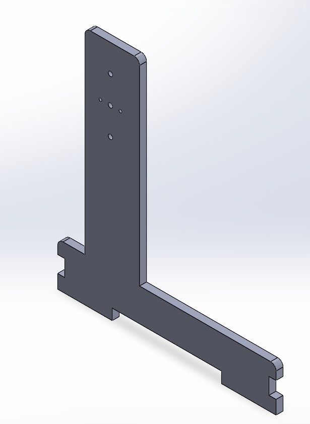
🔵 X Axis – Gantry (Left to Right)
The X axis consists of a rigid gantry that supports the Z axis assembly. It allows movement from left to right along the width of the machine. In the SolidWorks model, this is represented by a horizontal beam with guide rails and linear bearings for smooth movement.
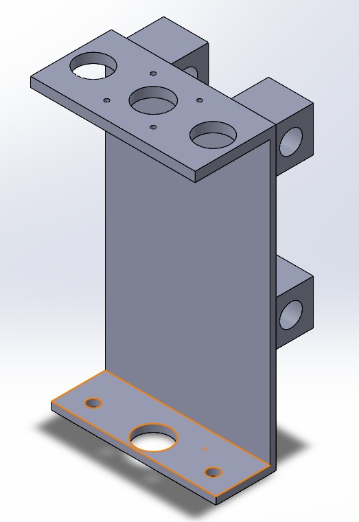
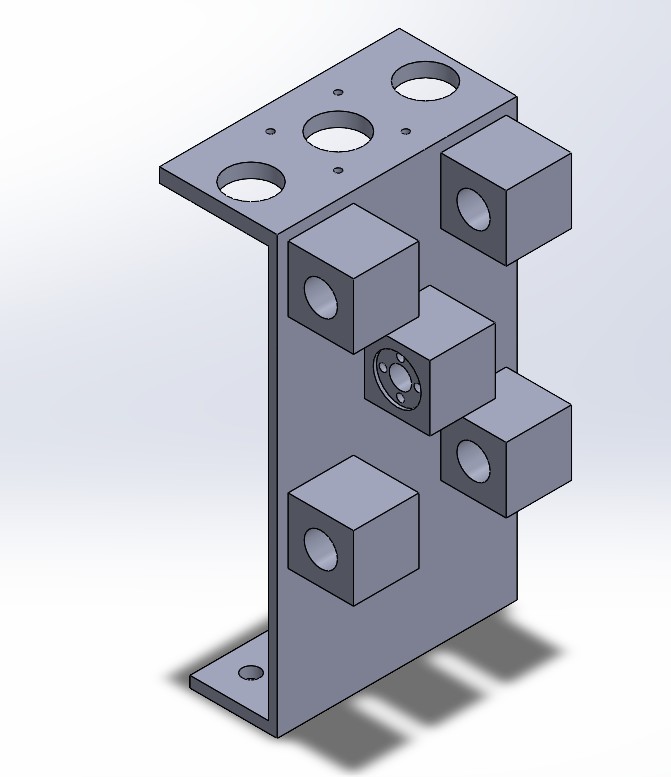
This part was carefully designed using real component dimensions to ensure a proper fit during assembly:
- 📐 Overall Dimensions: 200 mm tall, 110 mm deep (extrusion), 50 mm long at the top, 40 mm at the base, and 4 mm wall thickness.
- ⚙️ Top Section: Includes a dedicated space for mounting a NEMA 17 stepper motor and two circular bearing cutouts (left and right) to stabilize the shaft and improve fluid motion.
- 🧩 Bottom Section: Also includes aligned circular bearing mounts for additional support.
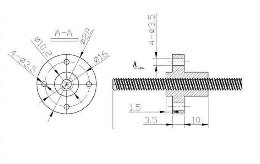
- 🔩 Back Center: A rectangular space was added for the installation of a T8 nut, which allows the leadscrew-driven movement of the Z-axis assembly.
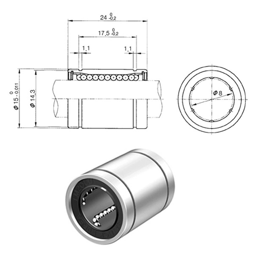
- 🛠️ Back Top and Bottom: Two 15.22 mm diameter cylindrical holes were created to house LM8UU linear bearings (8×15×24 mm), based on the technical drawing of this bearing. These guide the 8 mm shafts used for lateral motion.
📏 Design References: The dimensions for these cutouts were based on the official mechanical drawings of the LM8UU linear bearings and the T8 brass nut, ensuring compatibility and precision during the mechanical assembly.
📎 Reference Drawings
🔴 Y Axis – Bed Movement (Forward and Backward)
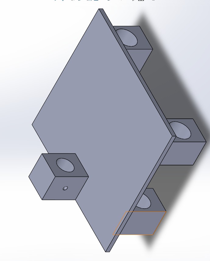
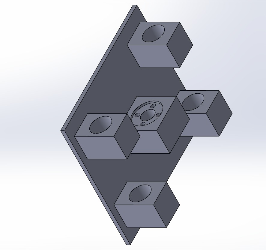
In this CNC configuration, the bed itself moves forward and backward, making it the Y axis. This is a classic design in fixed-gantry machines. In SolidWorks, the bed was modeled with mounting holes and space for the linear guides and motor that drive its motion.
For the construction of the Y-axis, I designed and printed a total of 5 support pieces to hold and guide the movement of the bed:
- 🧩 3 Central Pieces: Placed under the bed's center area. These include 15.22 mm diameter cylindrical holes designed to house LM8UU linear bearings (8×15×24 mm), allowing smooth motion along the 8 mm guide rails.
- 🔧 2 Side Pieces: Positioned at the lateral ends of the bed. These were designed to support circular 8 mm bearings, helping to stabilize the shaft at both ends and ensuring improved rotational movement.
All parts were modeled in SolidWorks based on the technical dimensions of the LM8UU bearing and T8 nut to ensure a precise fit. The components were printed in 3D using a Prusa printer with 15% infill density, providing a good balance between strength and weight.
For the bed itself, I used a 40 cm × 40 cm MDF board to provide a flat and stable platform. Since I needed the surface to remain smooth and undamaged, I chose strong adhesive glue to attach the printed support pieces instead of screwing them in. This method preserved the flatness of the MDF and still provided sufficient stability for the bed’s movement.
The modular setup allows precise alignment of the components, facilitating smooth and consistent motion along the Y-axis.
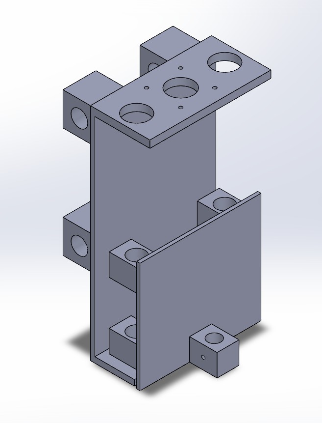
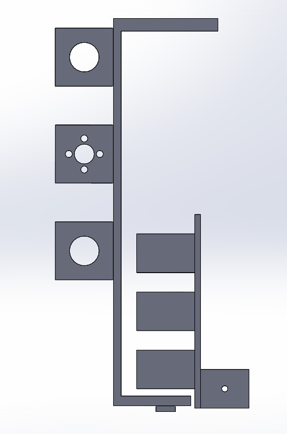
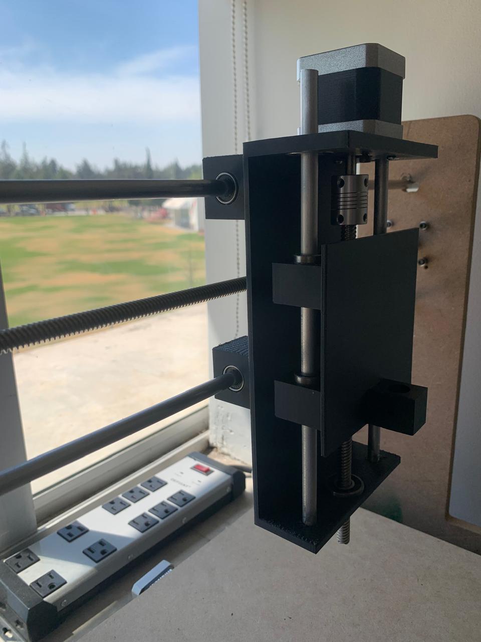
🟢 Z Axis – Pen Mount and Vertical Motion
For the Z axis, I designed a vertical carriage specifically adapted to hold a fine-tip Sharpie marker, ensuring precision in drawing tasks. I based the cylindrical cutout on the diameter of the marker, which is approximately 12.5 mm. To secure the marker in place, I added two M3 screw holes on the sides.
The rear part includes a mounting space for a T8 leadscrew nut to control vertical motion precisely. I also added corner cutouts to hold 4 linear bearings (LM8UU), one on each side, for smooth and stable vertical movement.
- ✏️ Marker Holder Diameter: ~12.5 mm (Sharpie fine tip)
- 🔩 Side Holes for Screws: 3 mm (M3 size)
- ⚙️ Rear Nut Slot: Designed for standard T8 nut (square flange type)
- 🛠️ Linear Bearing Slots: Four 15.22 mm diameter holes for LM8UU bearings (8×15×24 mm)
- 📐 Overall Plate Dimensions: 100 mm × 110 mm, 3 mm thick
To verify the fit and alignment of the holes, I assembled the Z axis carriage with the X axis slider. This test was crucial to ensure that the linear bearings and the T8 screw mount aligned correctly before printing the final version.
All parts were 3D printed using a Prusa printer with 15% infill for a balance between strength and print speed. This setup ensures stable vertical control of the Sharpie, essential for the CNC’s drawing functionality.
📁 Design Files by Axis
🟥 X Axis
- Download X Axis – Gantry (Left to Right) – Includes 3D models and technical drawings of the gantry components.
🟩 Y Axis
- Download Y Axis – Bed Movement (Forward and Backward) – Contains design files for the moving bed and its support parts.
🟦 Z Axis
- Download Z Axis – Pen Mount and Vertical Motion.zip – Includes the pen holder design and the components for vertical movement.
These SolidWorks models were essential for planning the assembly process and ensuring proper alignment of all components before manufacturing.
🛠️ Cutting Aluminum Guides and Leadscrews
To enable precise movement along the X and Y axes, I purchased two 50 cm long T8 leadscrews from Mercado Libre. Each leadscrew came with a matching T8 brass nut. The total cost was approximately $15 USD for both, including shipping.
You can find the product here: T8 Leadscrew with Nut – 50 cm on Mercado Libre
For the linear motion system, I also cut 8 mm diameter aluminum shafts. To ensure a proper fit and avoid tightness during installation, I cut them slightly longer than the exact dimensions needed. I used a hacksaw (segueta) for cutting and then sanded the ends with sandpaper to remove sharp edges and smooth the surface.
I did not take a photo of this part of the process, but I asked ChatGPT to generate an image to give an idea of the tools and materials used.
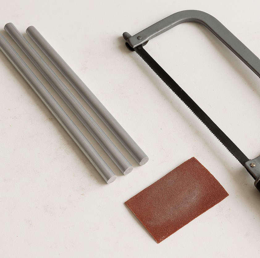
- 🔩 Leadscrews: 2x T8 leadscrews, 50 cm each (purchased pre-cut with brass nuts)
- 📏 Linear shafts: 8 mm diameter aluminum rods, manually cut slightly longer than needed, then sanded
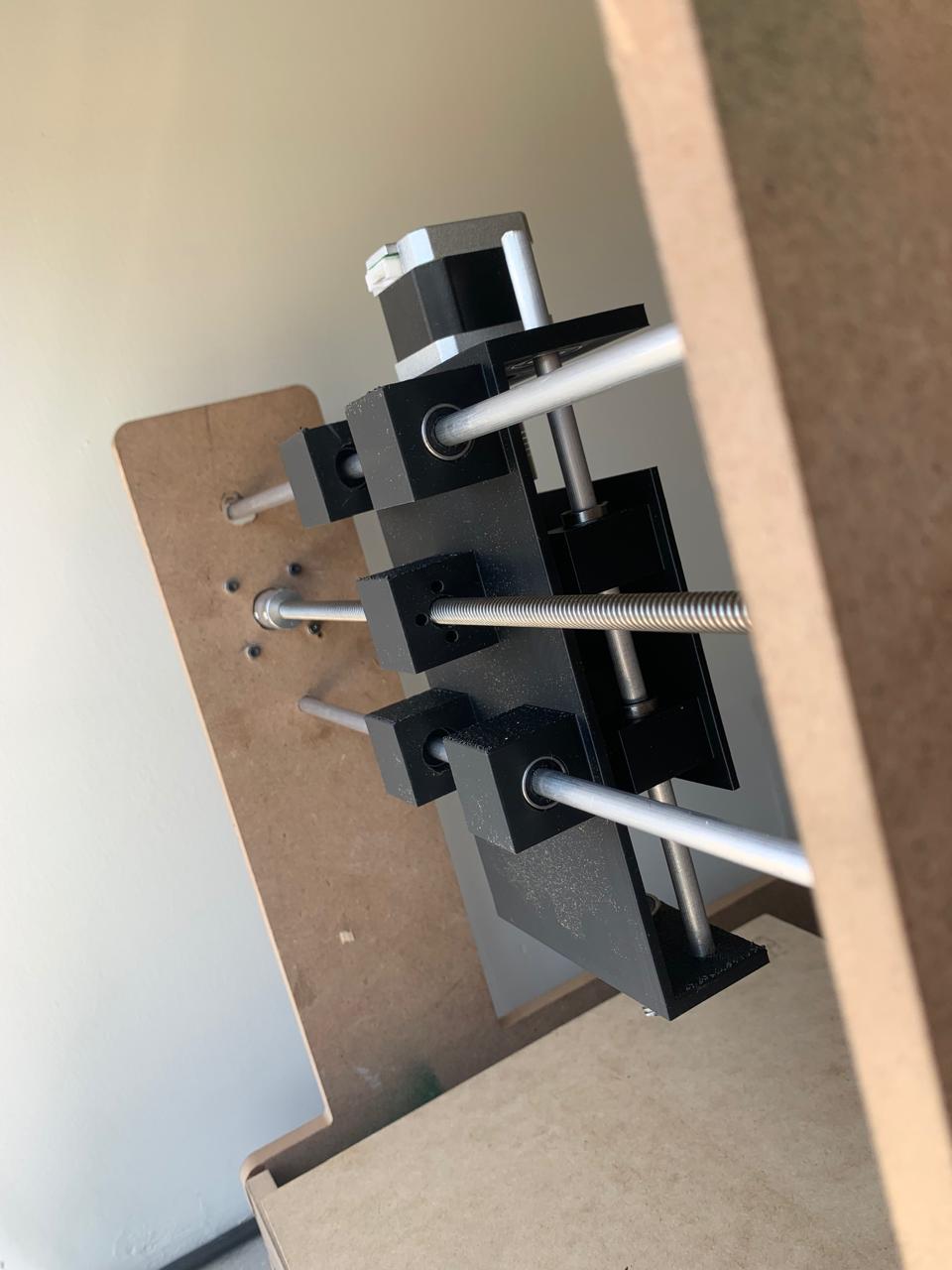
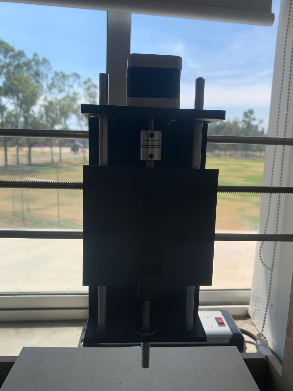
🛠️ Installing Leadscrews and Aluminum Shafts
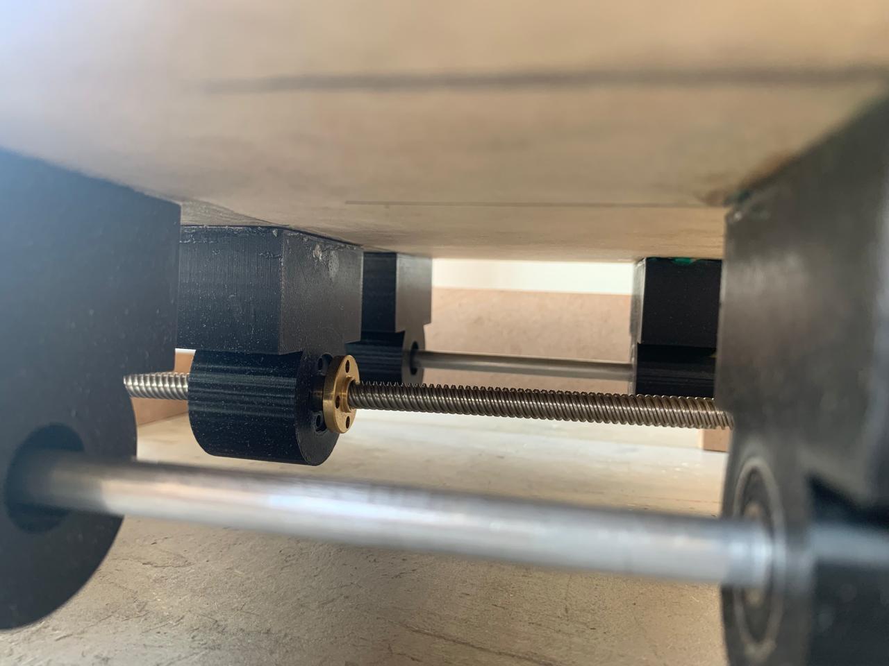
With the T8 leadscrews and aluminum shafts prepared, I proceeded to install them into the CNC's frame. The leadscrews were mounted on the X and Y axes to enable smooth and precise movement. I carefully aligned the shafts to avoid any misalignment that could affect the machine's performance.
I used the pre-drilled holes in the frame for the leadscrew mounts. For the aluminum shafts, I inserted them into the corresponding bearings to ensure minimal friction. It’s important to keep the shafts well-lubricated to prevent wear over time.
After securing the leadscrews and shafts, I checked for any play in the motion and made minor adjustments to ensure everything was tight and stable.
Here’s a picture showing the installation of the leadscrews and shafts.
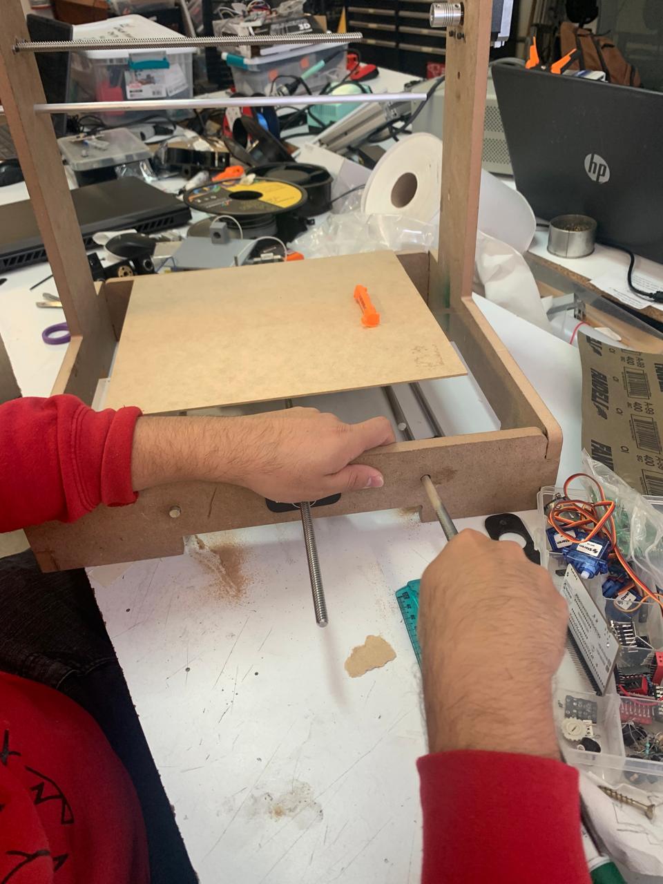
- 🔩 Leadscrews: Installed on X and Y axes for linear movement.
- 📏 Linear Shafts: Inserted into bearings for smooth motion.
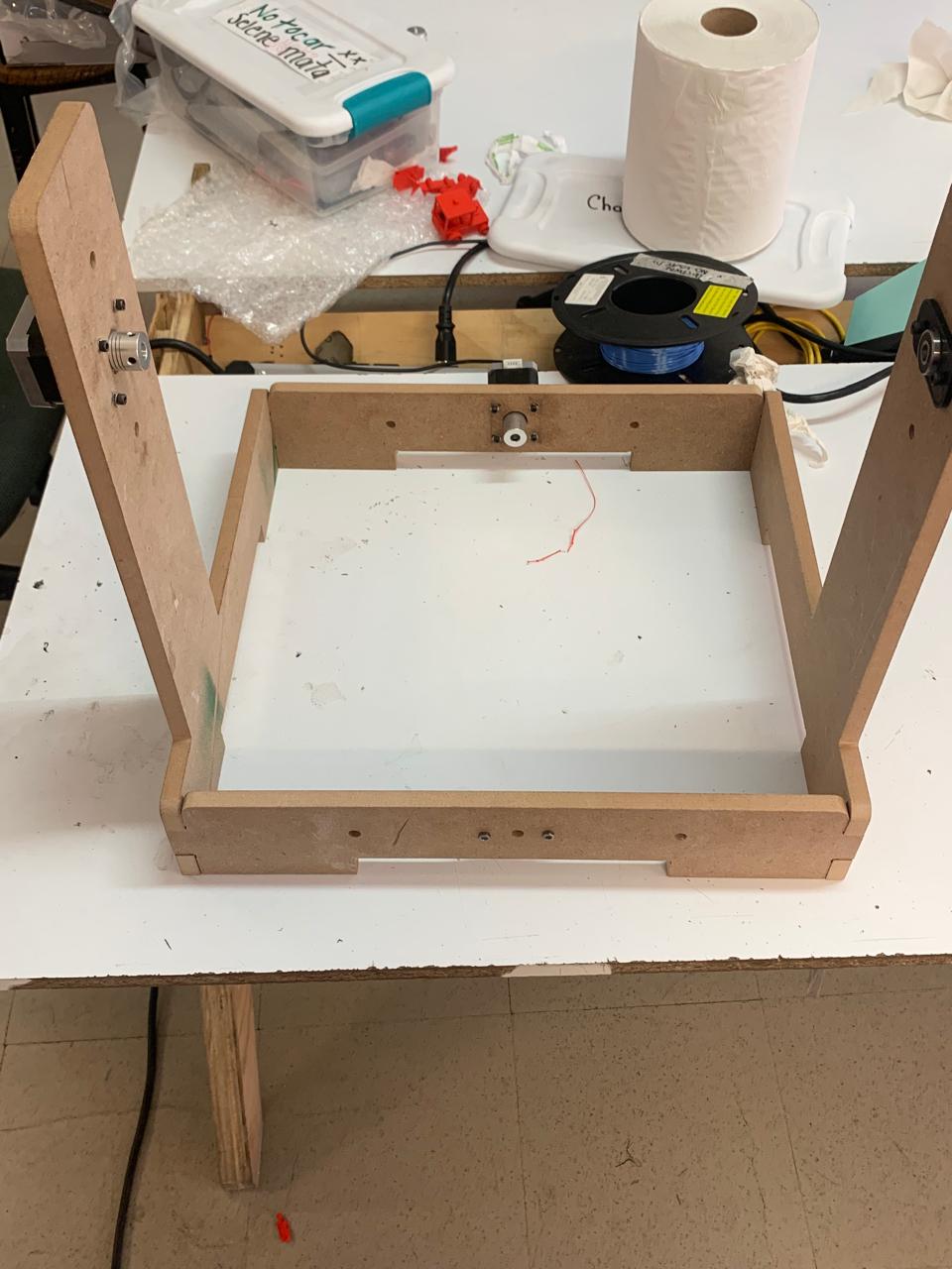
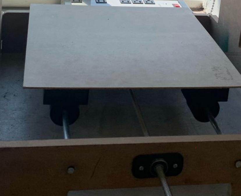
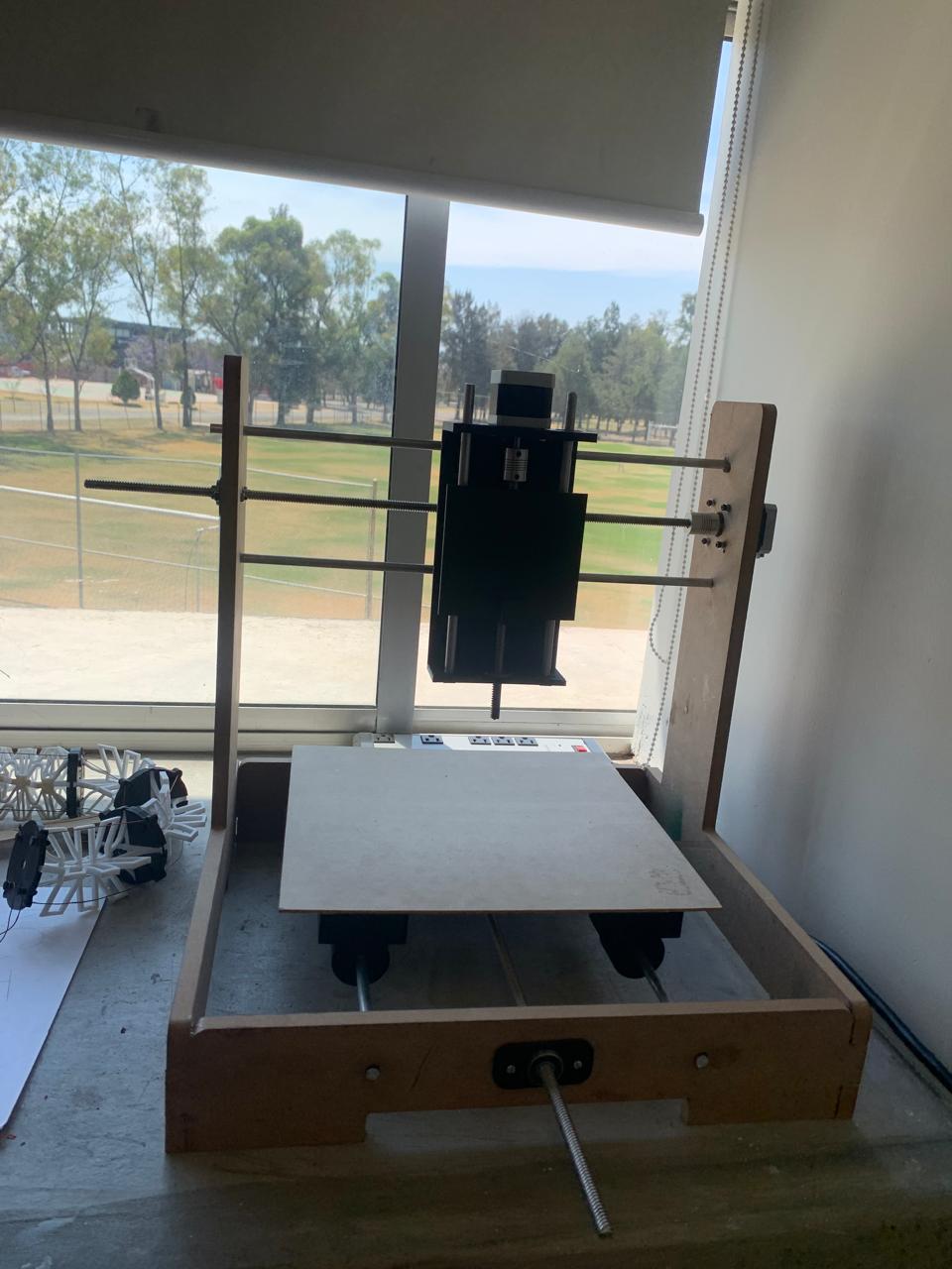
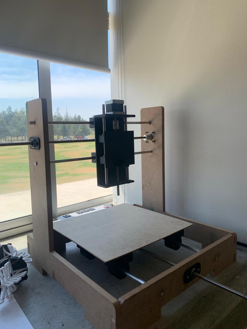
🔧 Final Assembly of the CNC
After completing the installation of the leadscrews, aluminum shafts, and other components, I assembled the CNC structure. The assembly includes the X and Y axes with all the necessary motors and supports. The frame is now ready to be tested and calibrated for precise movement and performance.
Below is the image showing the final assembly of the CNC machine with all components in place.

🔚 Conclusion
This project has been an incredible learning experience, from the design phase to the final assembly of the CNC machine. There were challenges along the way, such as manually sawing the aluminum shafts, which caused some concern about the alignment. I knew that precise alignment was crucial for the machine's correct functioning, and I was worried that any misalignment would affect performance. Additionally, drilling the holes in the frame was another issue I encountered. The use of a regular drill did not provide the necessary precision for the small, tight holes, which meant I had to do multiple tests and adjustments to get it right. This added extra time and effort to the process.
However, using a combination of techniques—from design in CAD software, to cutting with CNC machines, to 3D printing and manual work—allowed me to create a prototype that demonstrates what I’ve learned in the Fab Academy. This project reflects the rapid prototyping process and shows how problem-solving with the available tools can lead to functional solutions. The final result is not only a tangible prototype but also a showcase of the skills and knowledge gained throughout this journey.