12. Mechanical design & amp; machine design
This week's assignment involved the design and construction of a CNC as a team. To ensure effective teamwork, the tasks were divided into electronics, programming, and mechanics. The latter was assigned to my Fab colleague, Paula Rivero, and me.
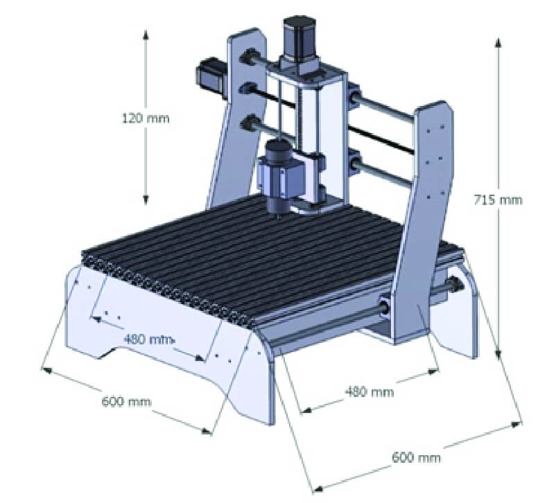
To design the structure of the CNC I found this image with a CNC model with measurements, the measurements and the figure of the structure was useful as a guide to design the structure of our CNC.
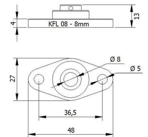
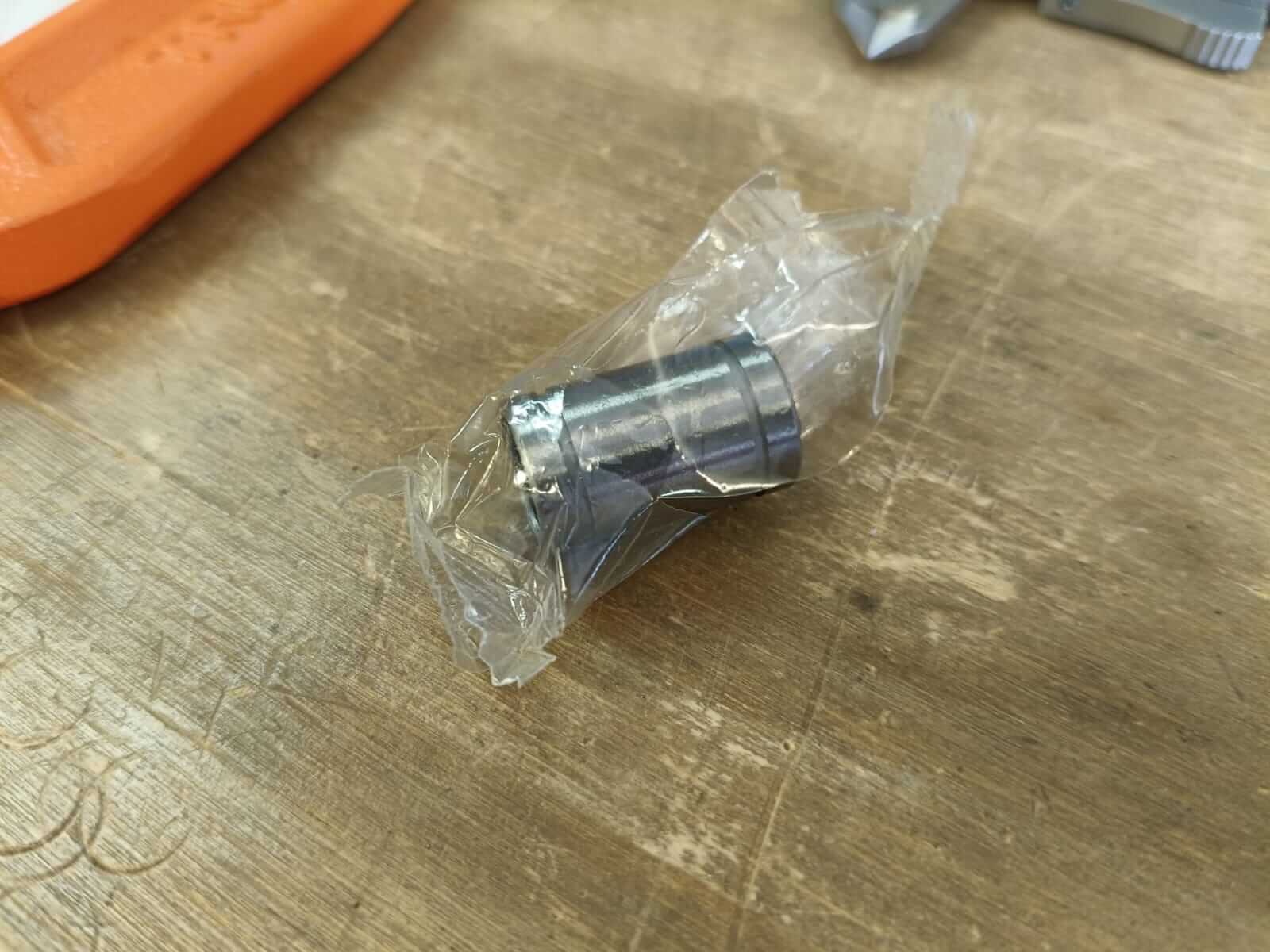
For the holes, we consider the measurements of the bearings to place them in the structures so that the 8mm Acme screw can pass and rotate without problems.
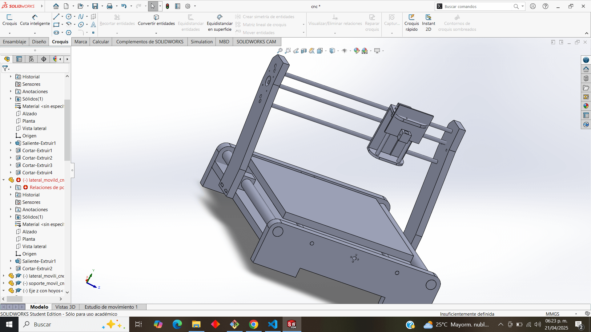
As an initial design, we made individual pieces of the structure and put it together in the next assembly to get an idea of the structure.
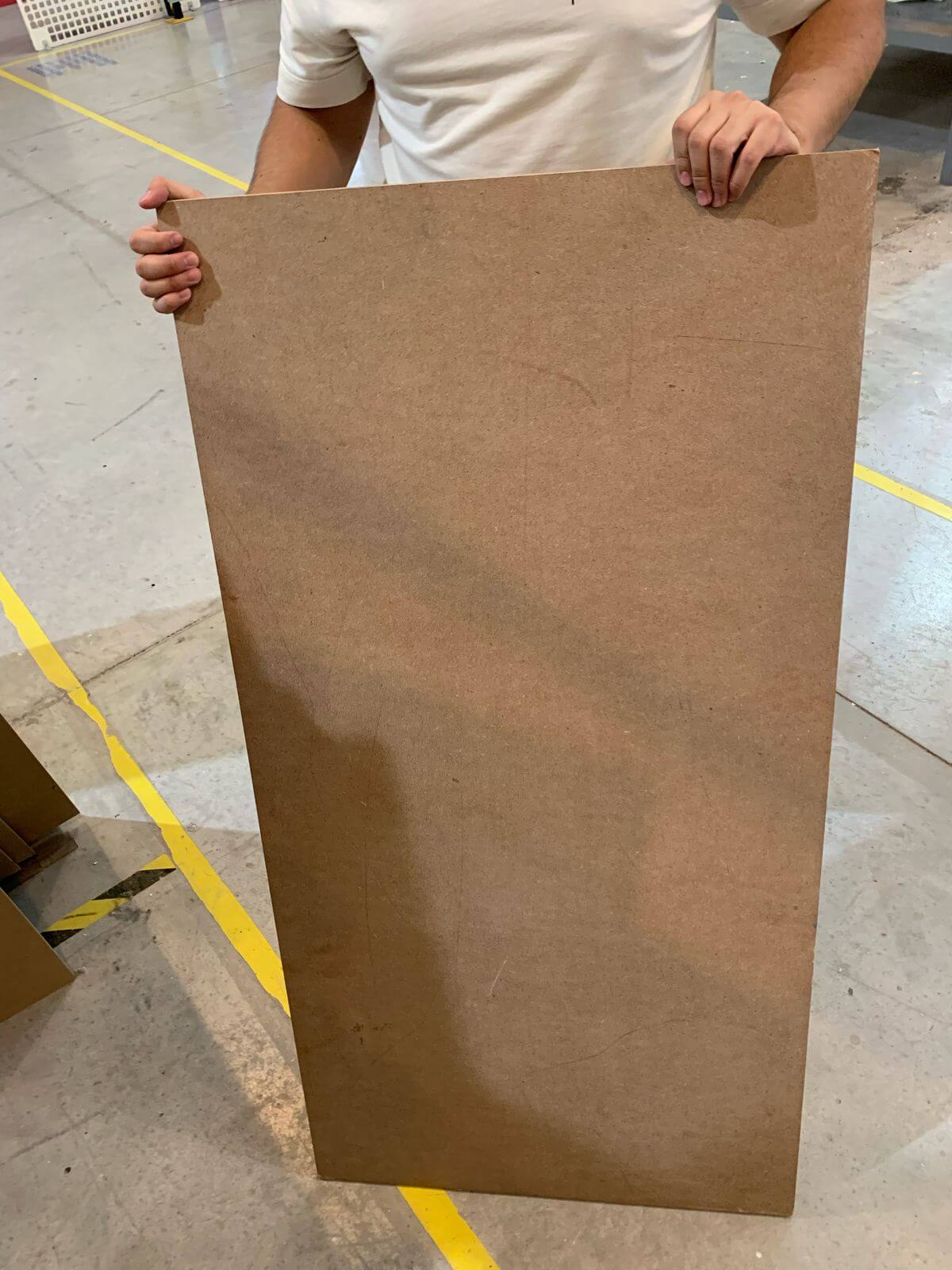
After presenting the group's design idea, suggestions were made by the team, leading to a redesign of the structure. Now that we had the design, we needed the material with which we would build it, so we chose thick MDF for the structural pieces, and we would use Ibero's Asia router to cut it.
We create the .crv file in the V-Carve for the router to read, we place the mdf on the router bed and position it at the origin, we load the file to the machine and start cutting.
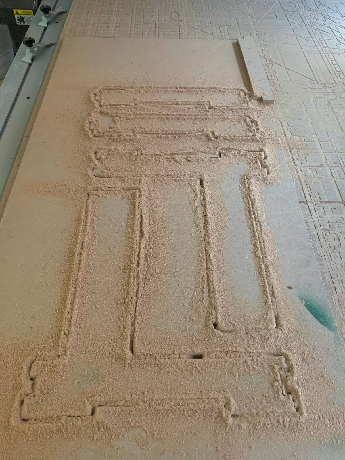
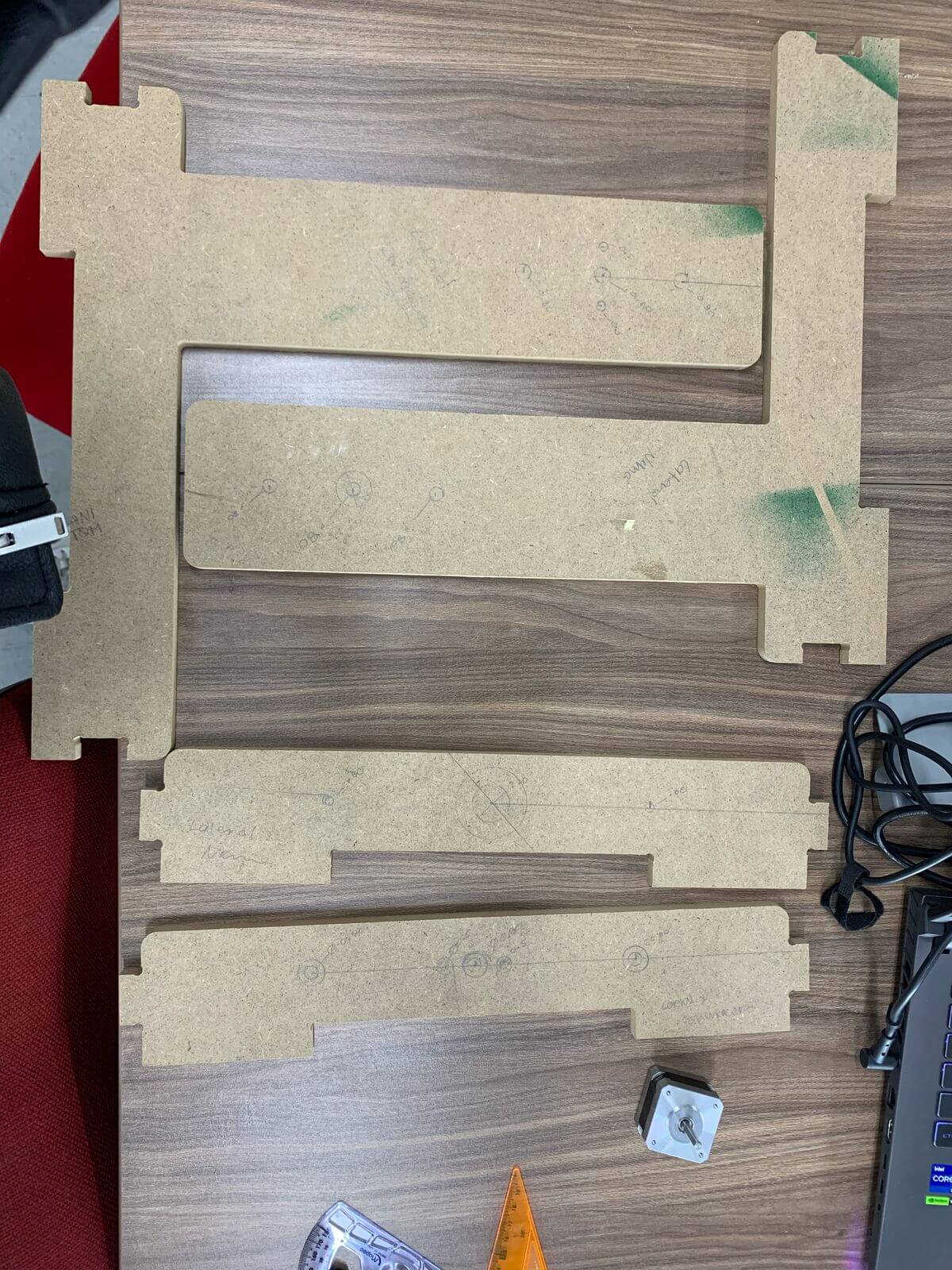
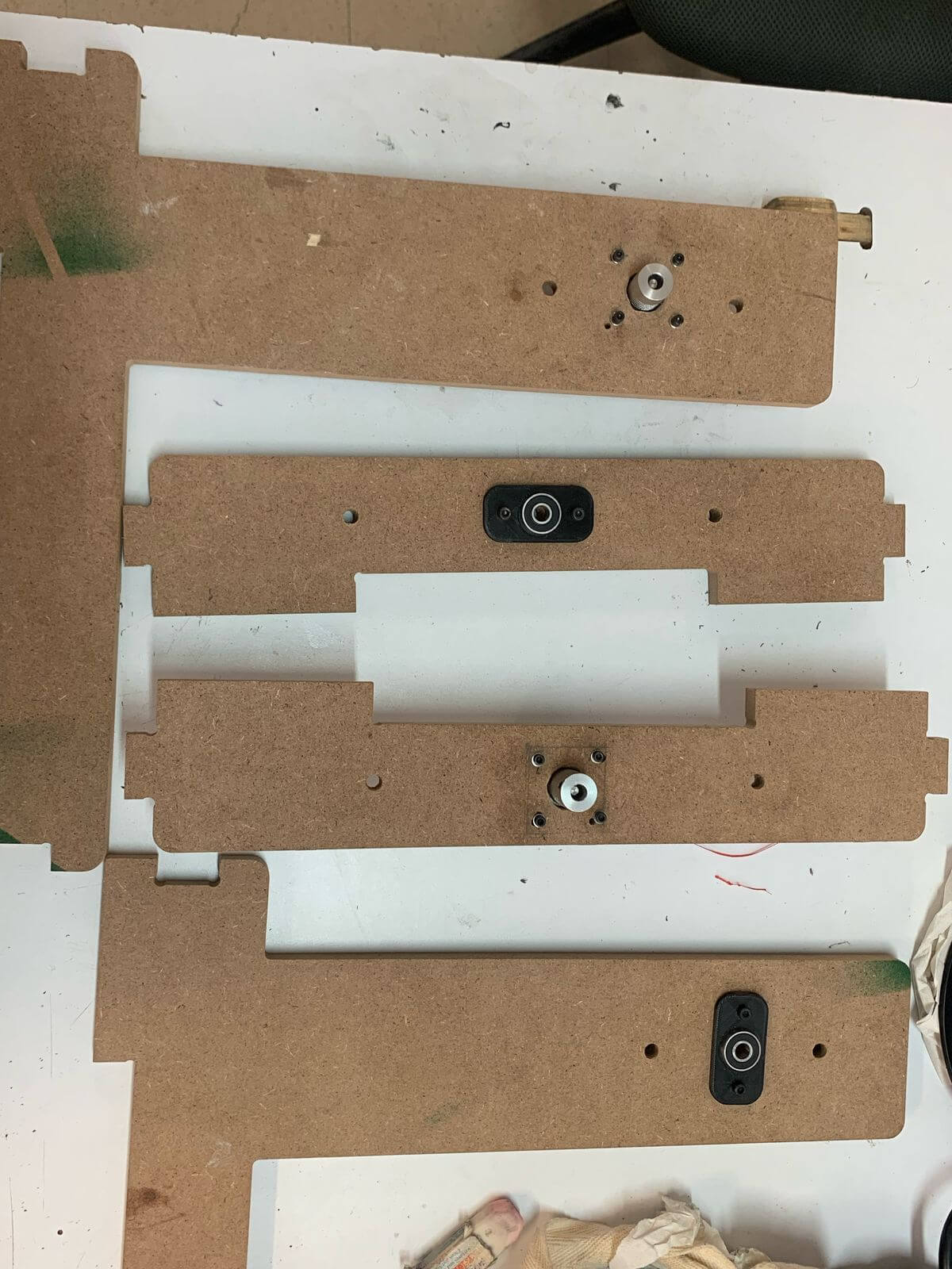
This was the final result of the cut.
Here's a cleaner look at how the pieces turned out:
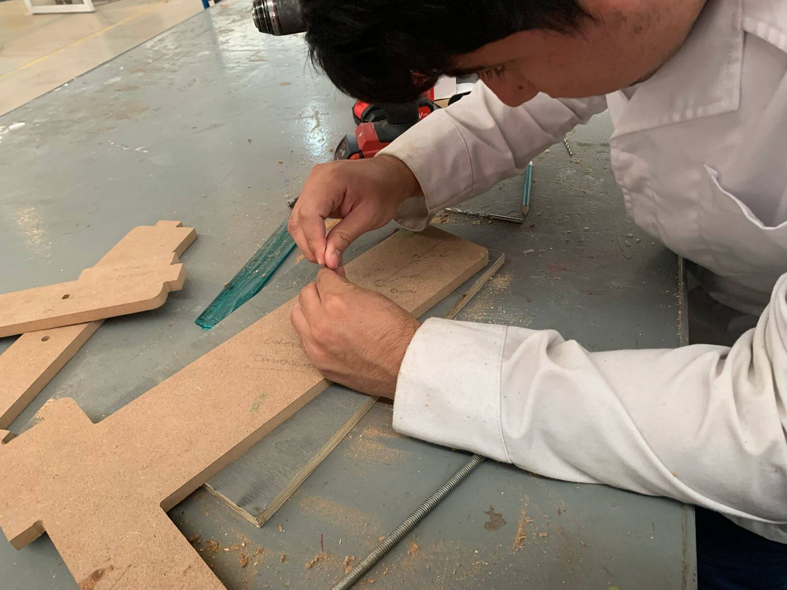
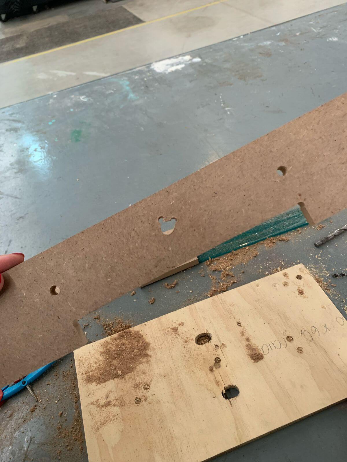
The cut didn't turn out as expected because the file we uploaded was incomplete and the holes for the holes were missing. So we decided to do it ourselves. We measured and marked where they should have been. To make the drilling easier with the drill, I opted to make a guide with a screw to make the hole and position the drill better.
Fun fact, we made a Mickey Mouse when drilling the MDF :)
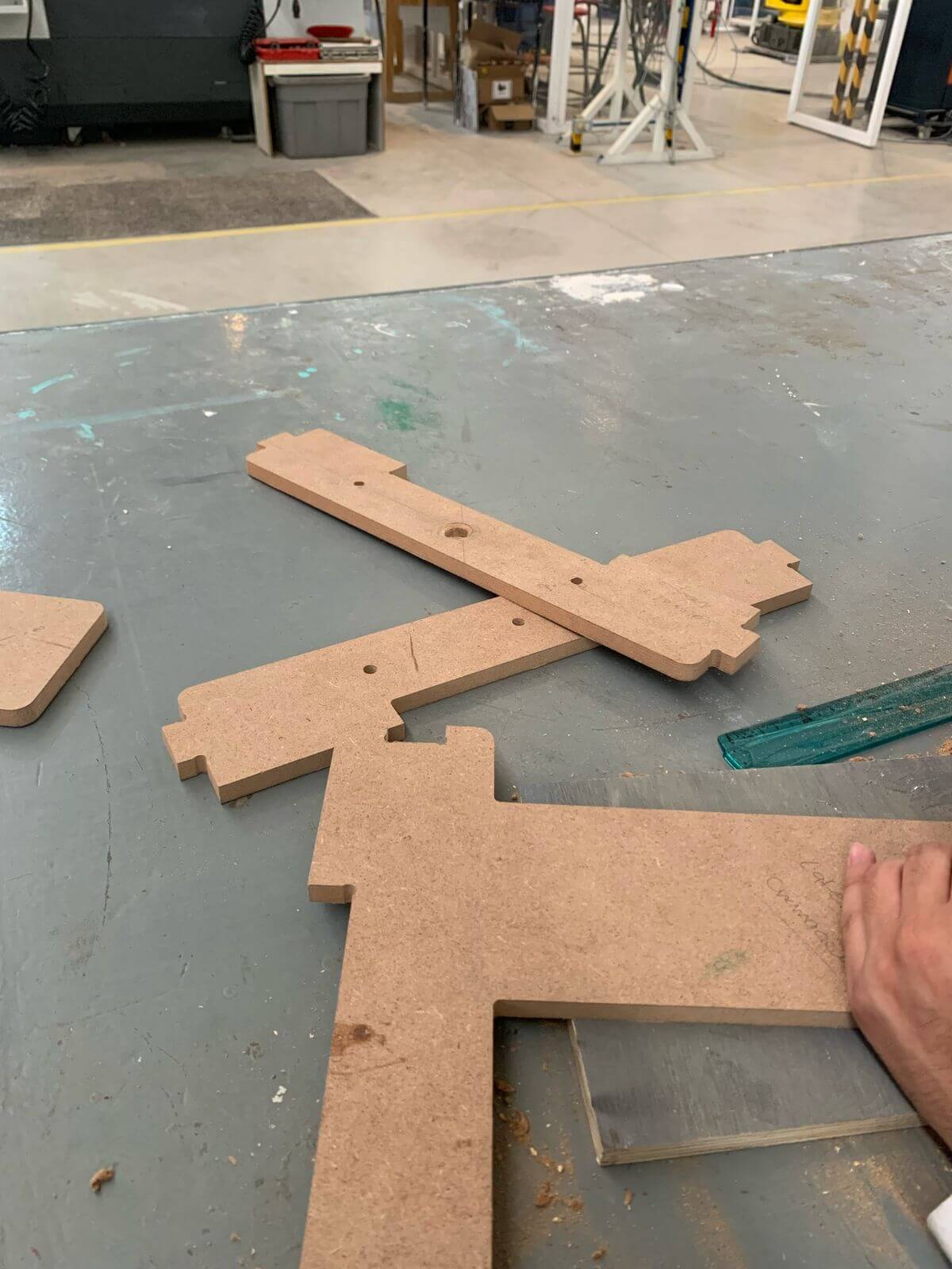
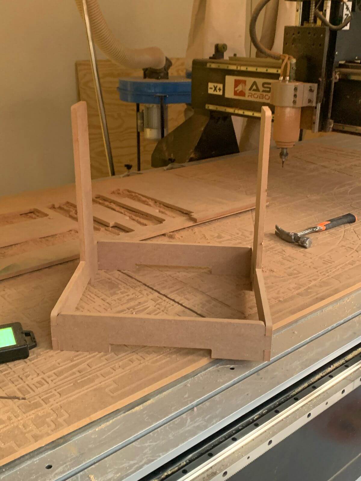
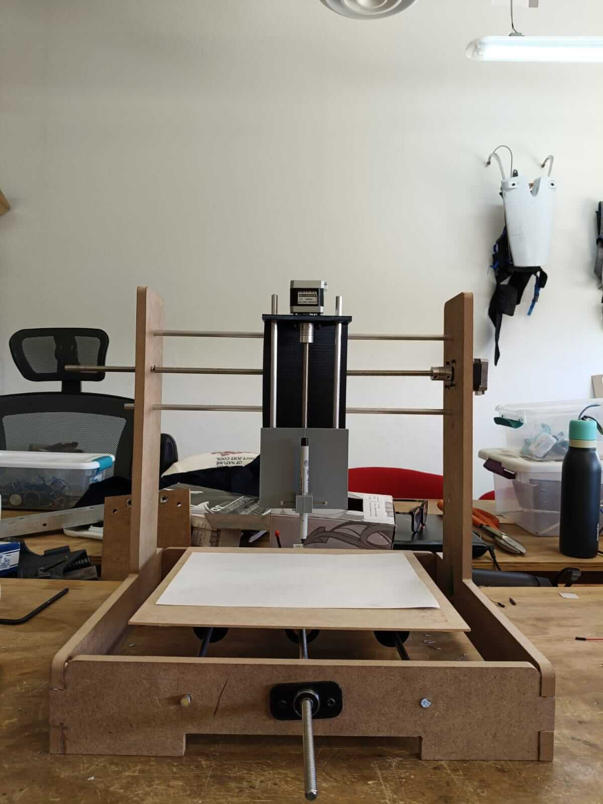
Once the holes are made, place the pieces where they correspond and assemble the structure, as follows.
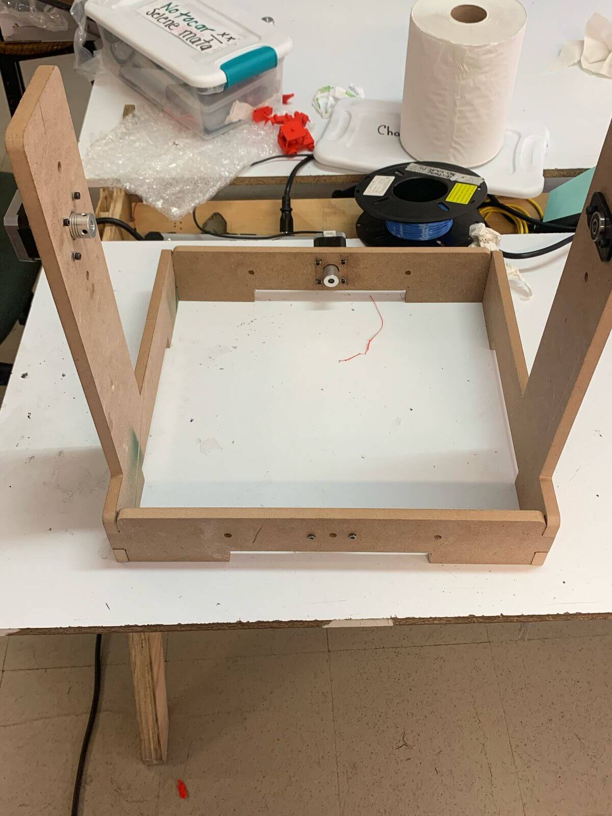
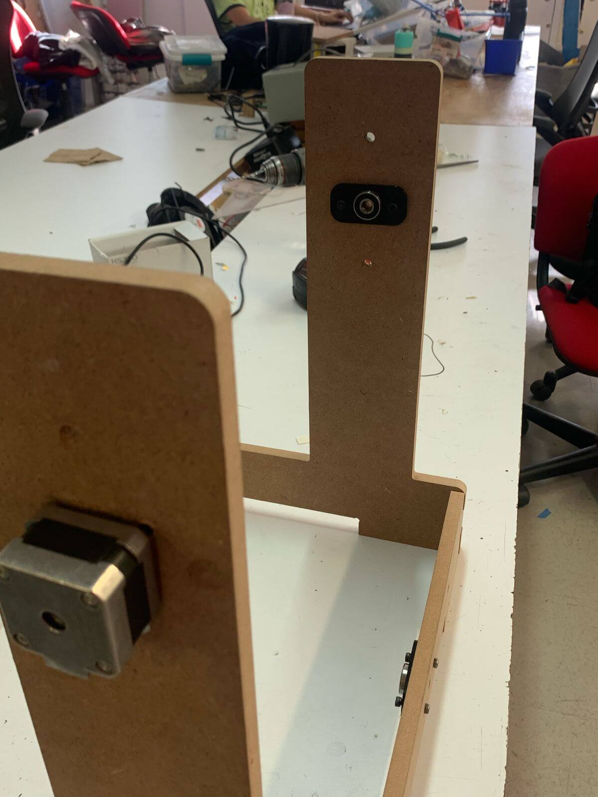
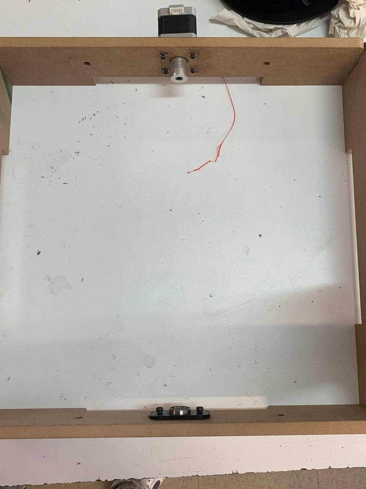
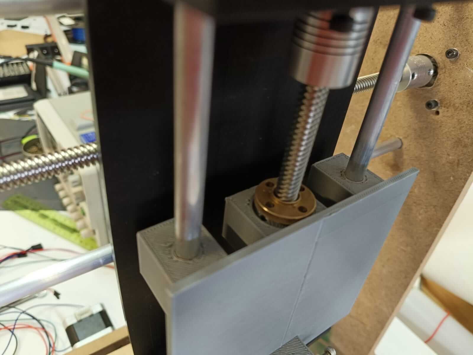
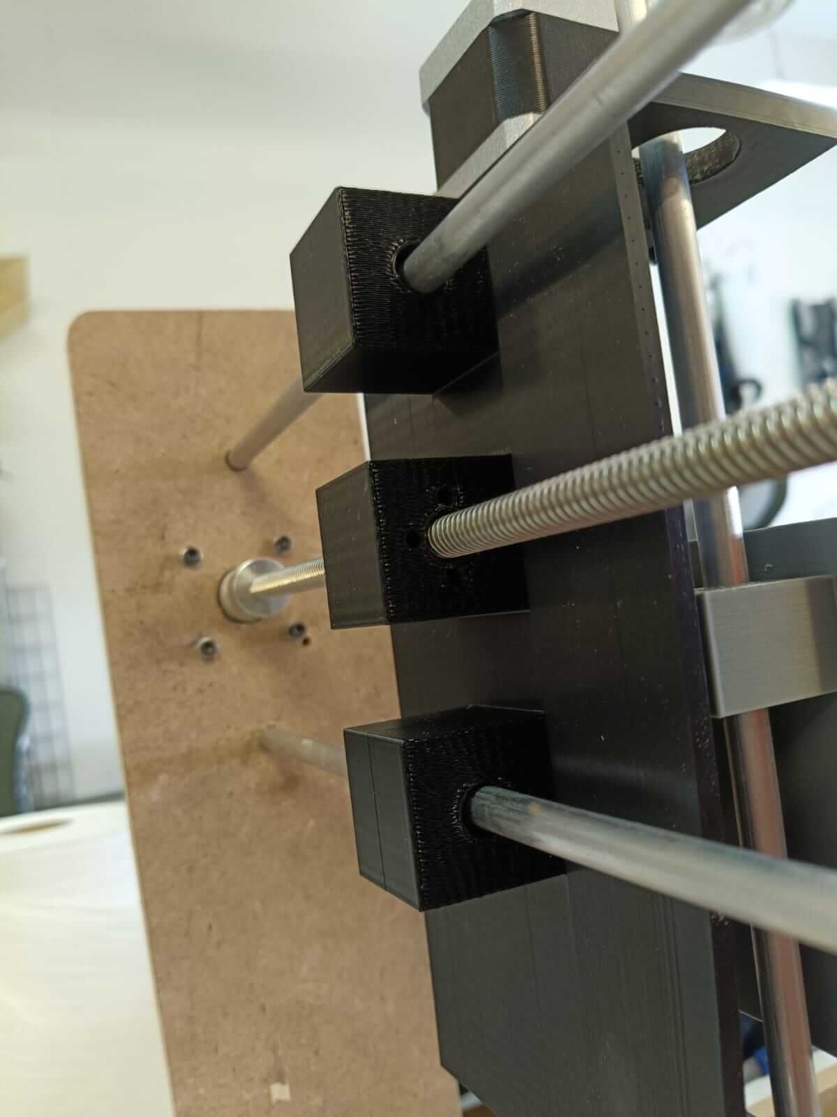
As part of the assembly, a 3D design was made of the pieces that would be guided by the rails, and the Acme screws and rails were cut to fit them into the structure.
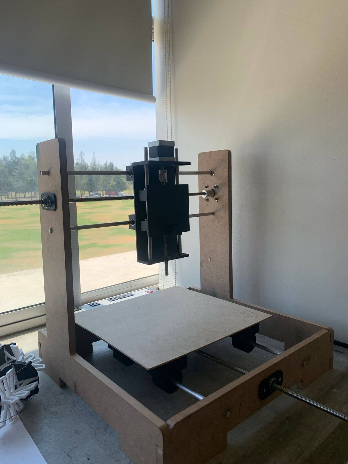
Putting everything together it would look like this:
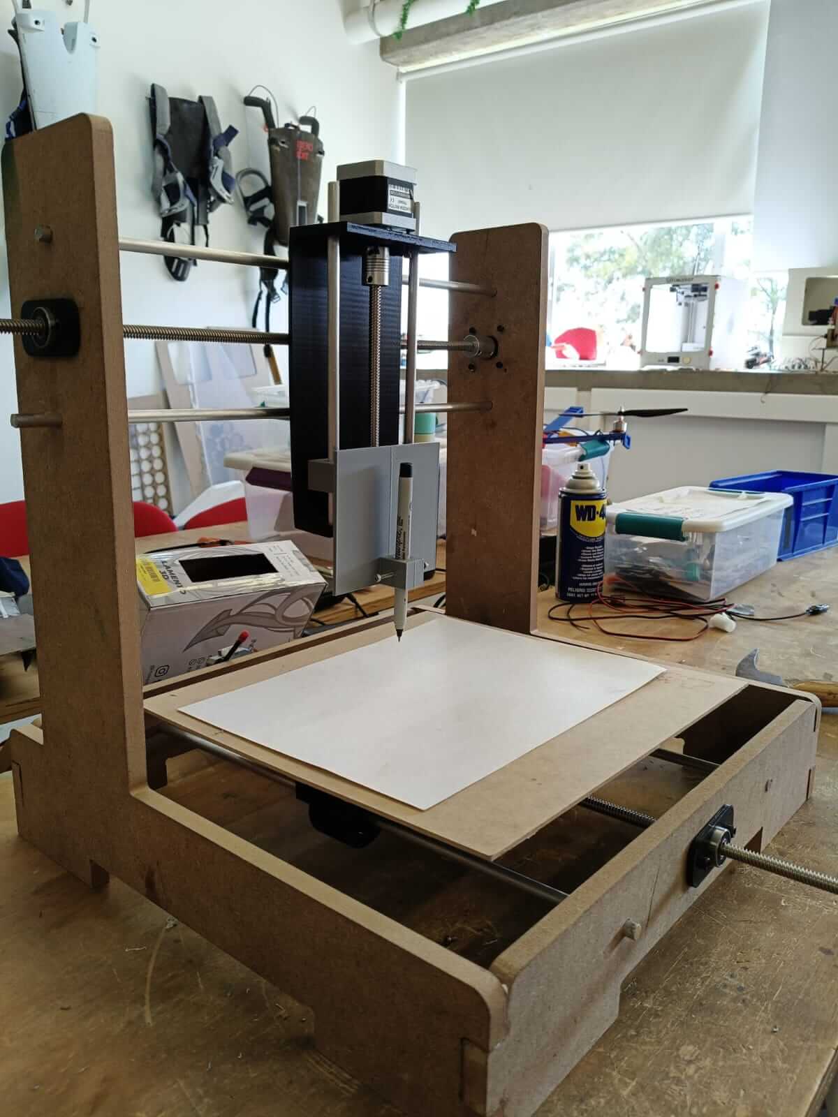
The other part of the team would then test the motors, verifying that the shafts rotate.
However, there were some failures as the motor was forced to spin too hard and couldn't even turn the shafts, so we had to check what was going on.
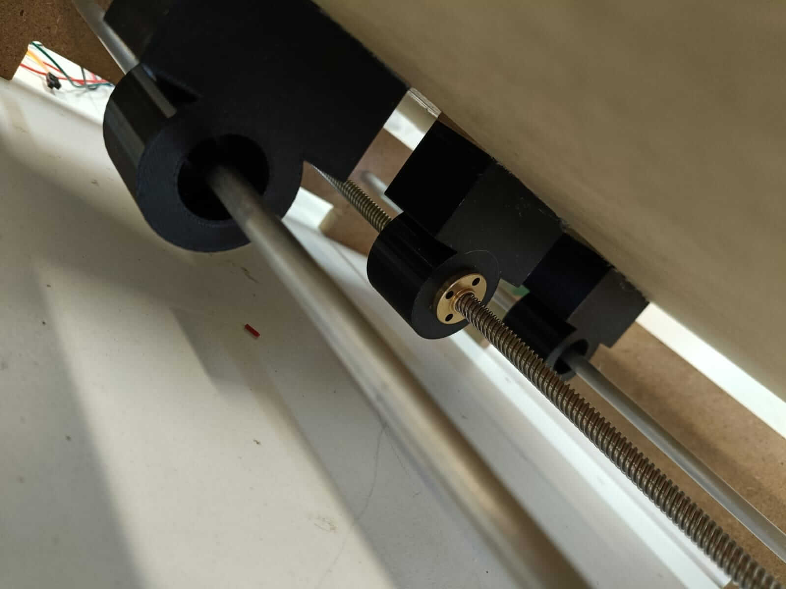
And after analyzing it, we noticed a few things, such as that the axes had a lot of friction because they were not properly aligned, and this caused the structure to open or close, making the CNC unstable. Another point we noticed was that the parts did not slide easily along the rails; this is because they do not have the bearings to rotate easily, so we decided to include them.
This is how the parts were redesigned to include the bearings.
This is how the redesigned pieces turned out:
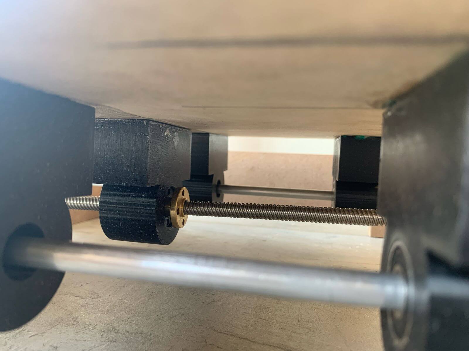
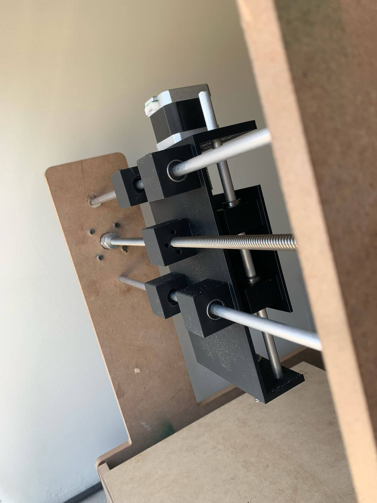
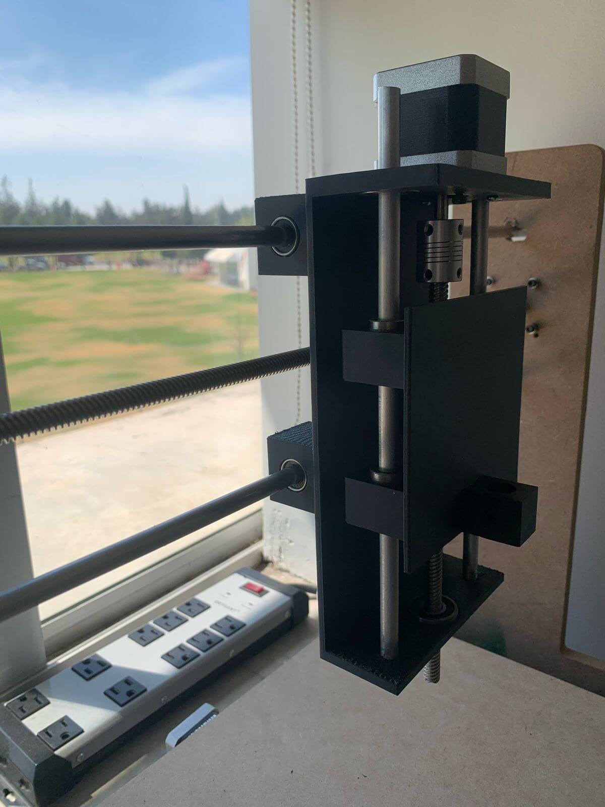
Some adjustments were also made to the axles. Specifically, some holes were drilled and expanded so that the rails, screws, and motors could fit better and prevent the axles from becoming stressed, to prevent friction, and therefore prevent the motors from being strained.
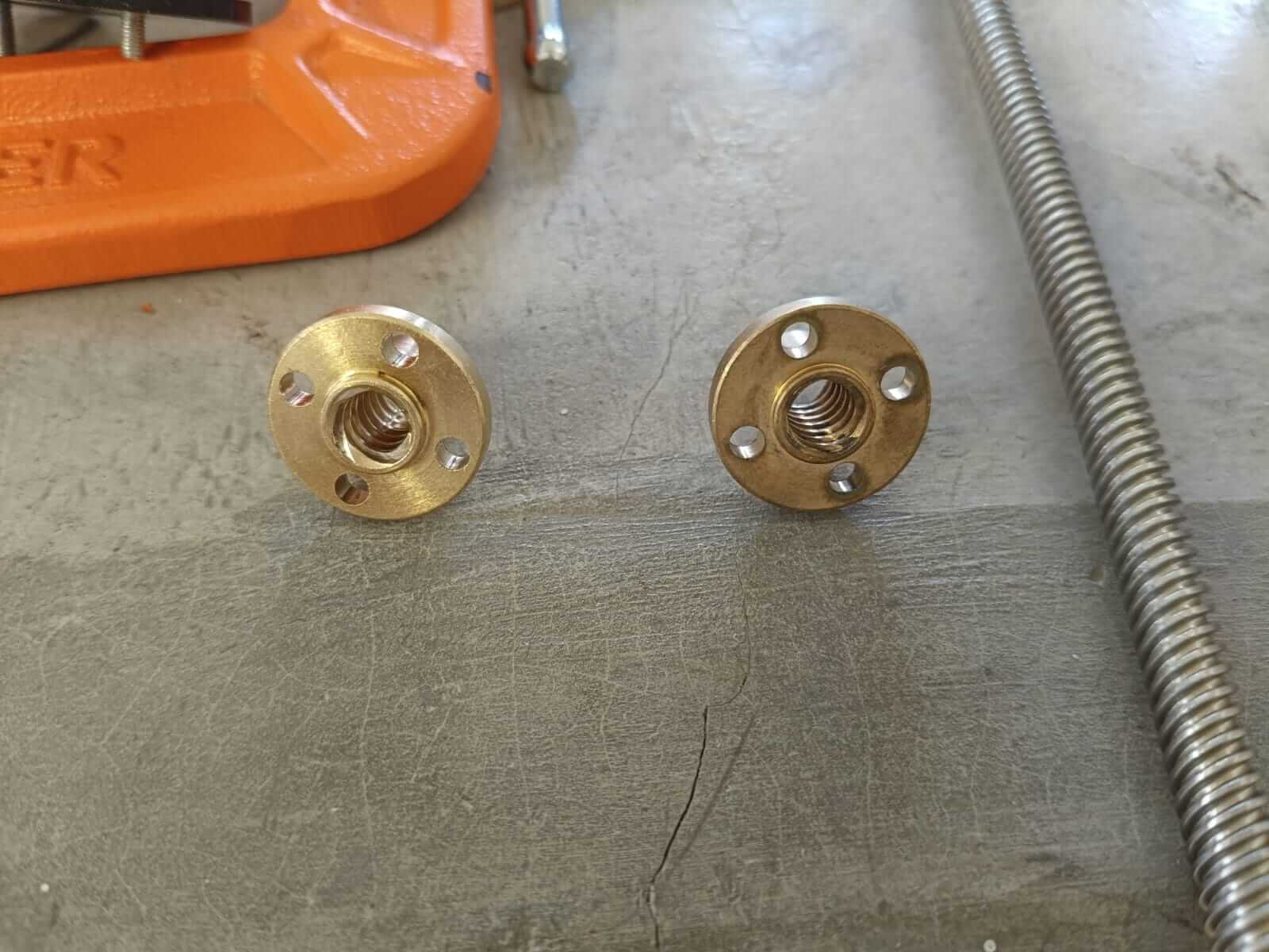
Another detail we noticed was that the bed's T8 nut didn't rotate smoothly on the screw, so I had to change it so the bed axle could move more easily.