My Final Project
This is where I will start defining my final project idea and its development process.
Early steps
My little brother loves a TV show where two teams play something similar to charades. Instead of acting and guessing a word, they need to guess the name of a movie or a song. With each turn, a different member throws a big fluffy die, and depending on the number on the top, there are specific rules that need to be followed to act out the phrase.They only have 20 seconds to act and guess.
Last Christmas I wanted to give my brother a die as a present, but there weren’t many options online. So, I came up with the idea to make a die that can detect the die´s position, with a Bluetooth-connected card box that opens to reveal the film/song name according to the number in which the die landed.
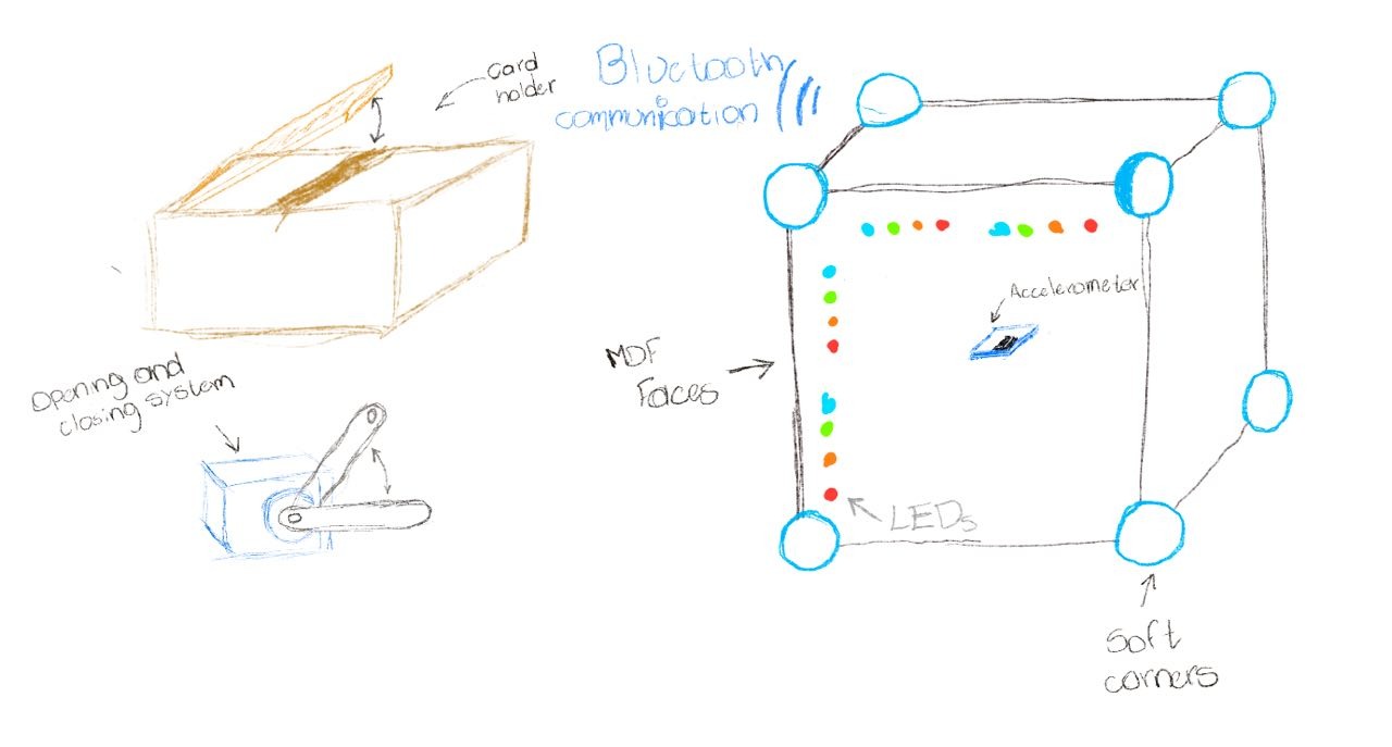
Here is the first sketch I made for this project.
The plan is to make a Dice that can identify and communicate via Bluetooth the number on top to a 3D-printed box where the movies and song cards will be contained. Depending on the number on the die, a different compartment will open. The difficulty will vary. Small numbers will reveal cards with short and easy names, while higher numbers will contain larger names or harder words to act.
The “cube” faces will be made of Medium-Density Fiberboard. Inside, it will have an accelerometer to detect the landing face. I´ll be using a XIAOnRF52840 sense with a built-in accelerometer. I am planning to make soft-rounded corners for the cube so it can bounce once it hits the ground.
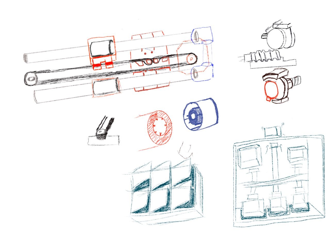
I decided to design a mechanism to open the different compartments according to each categories. I used Procreate to sketch my initial ideas:
The box will have a Bluetooth module to communicate with the die. I might add a small speaker to play the alarm sound when the time is up. The box will have a charging port and a battery to make it portable.
Final Project Planification
| Date | Activity |
|---|---|
| Jan 20 – Jan 28 | Final project definition |
| Jan 29 - Feb 4 | Logo design |
| Feb 10 - Feb 19 | XIAO accelerometer data via Bluetooth code |
| Feb 26 - Mar 4 | Card dispenser PCB design |
| Mar 12 - Mar 18 | PCB milling and soldering |
| Mar 26 - Mar 30 | DC motor with encoder programming for the Card dispenser |
| Mar 30 - April 1 | PCB production for the stepper motor and XIAO |
| April 2 - April 9 | Communication between the board inside the die and the card dispenser board |
| April 15 | Die material definition |
| April 21 - April 29 | Die creation with a mold |
| May 1 - May 6 | Card dispenser design |
| May 7 – May 14 | Build the Card dispenser |
| May 15 – May 27 | Final program and fully operational game |
| May 28 – June 1 | Final project slides and video |
| June 2 | Final project finished |
| June 09 – June 13 | Final project presentation |
week 2
This week I made my final project´s logo using Inkscape and Procreate
Procreate

Inkscape
week 4
This week I programmed in two different programming languages the XIAOnRF52840 that is going to be inside the die to send the accelerometer data via Bluetooth.
I liked the CircuitPython version the most, which I´m planning on using for the final code.
week 6
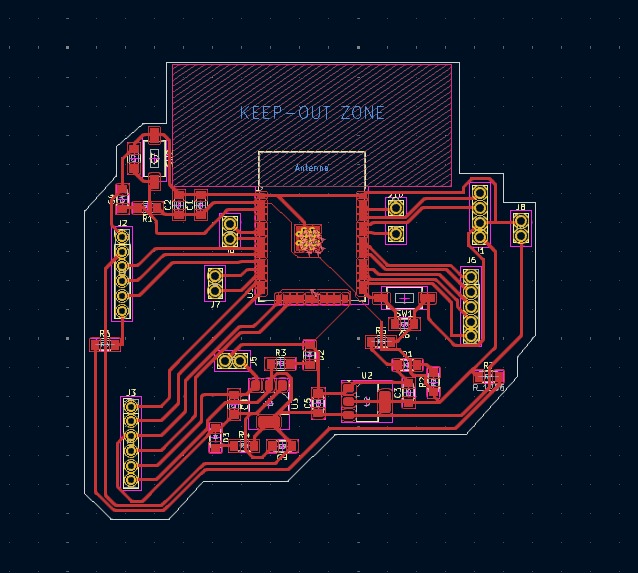
I designed the PC with an ESP32 for the card dispenser
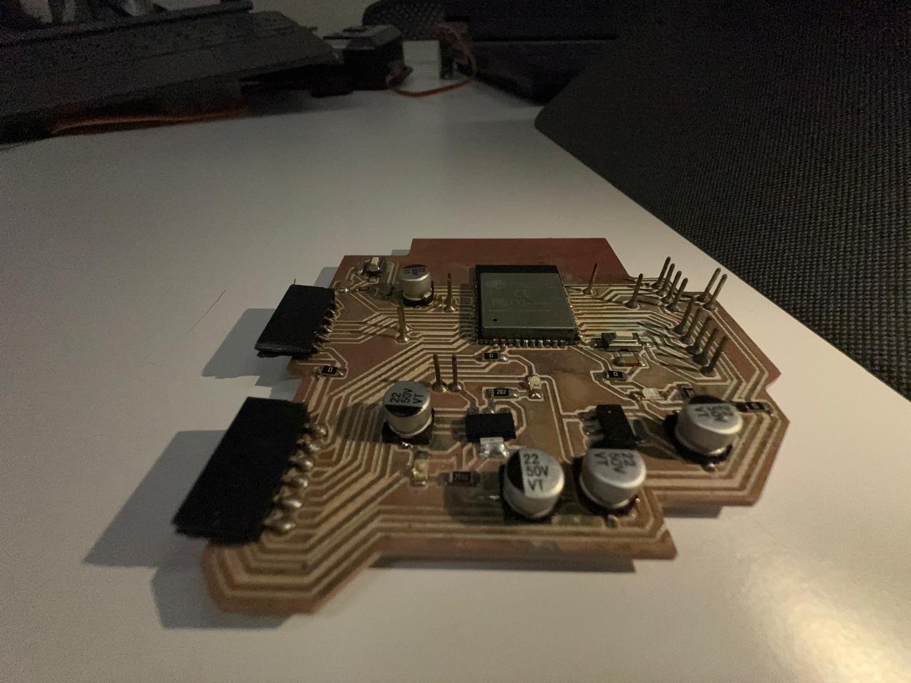
week 8
I milled and soldered the PCB I designed during week 6
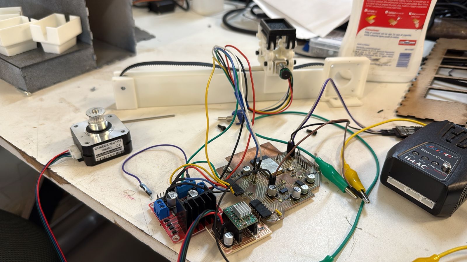
week 10
I programmed one of the motors that I will be using on my card dispenser
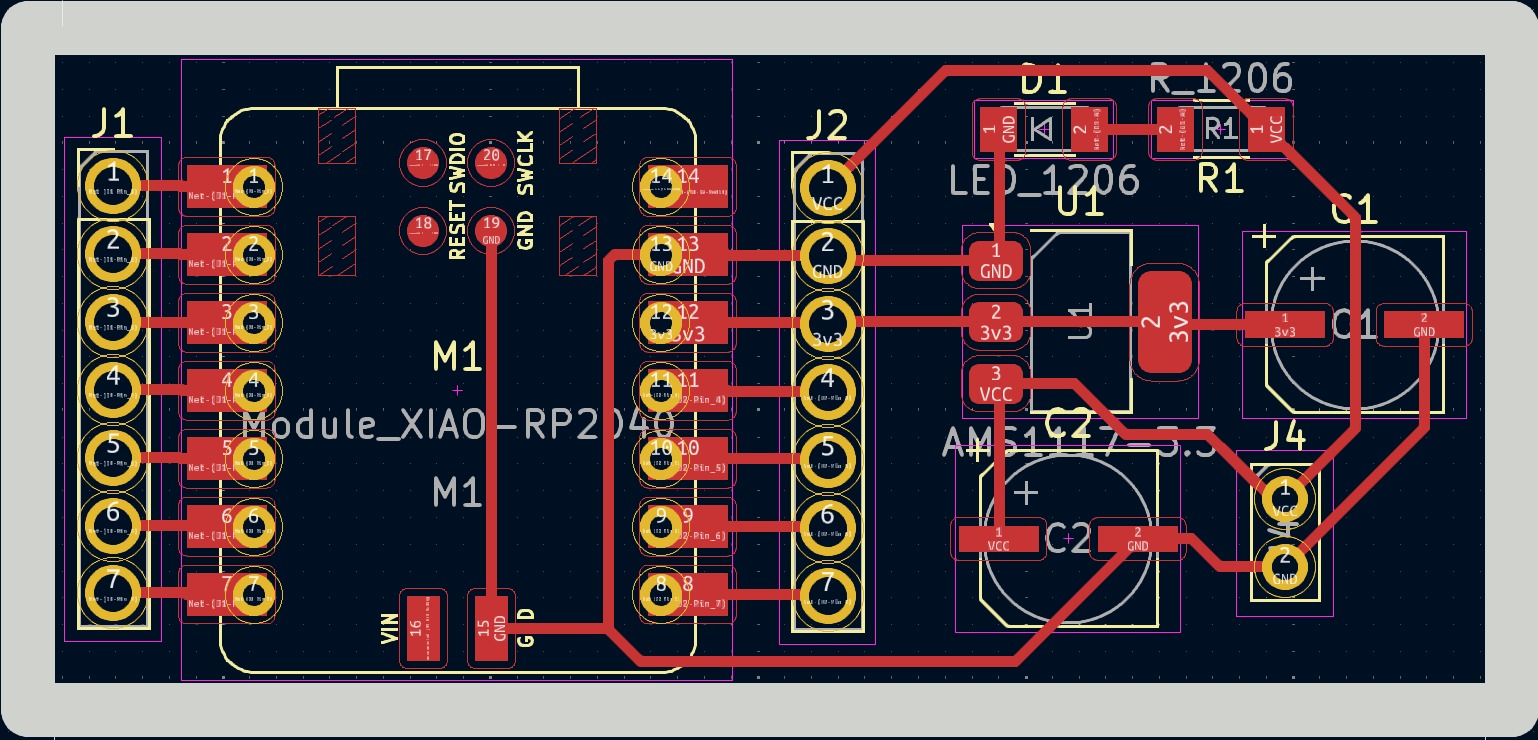
I designed a small PCB for the stepper motor I´ll be using, and an extra PCB for the XIAO.
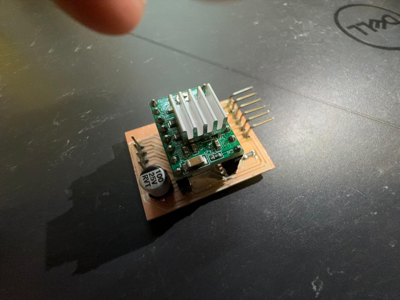
Here is the schematic for the stepper motor PCB
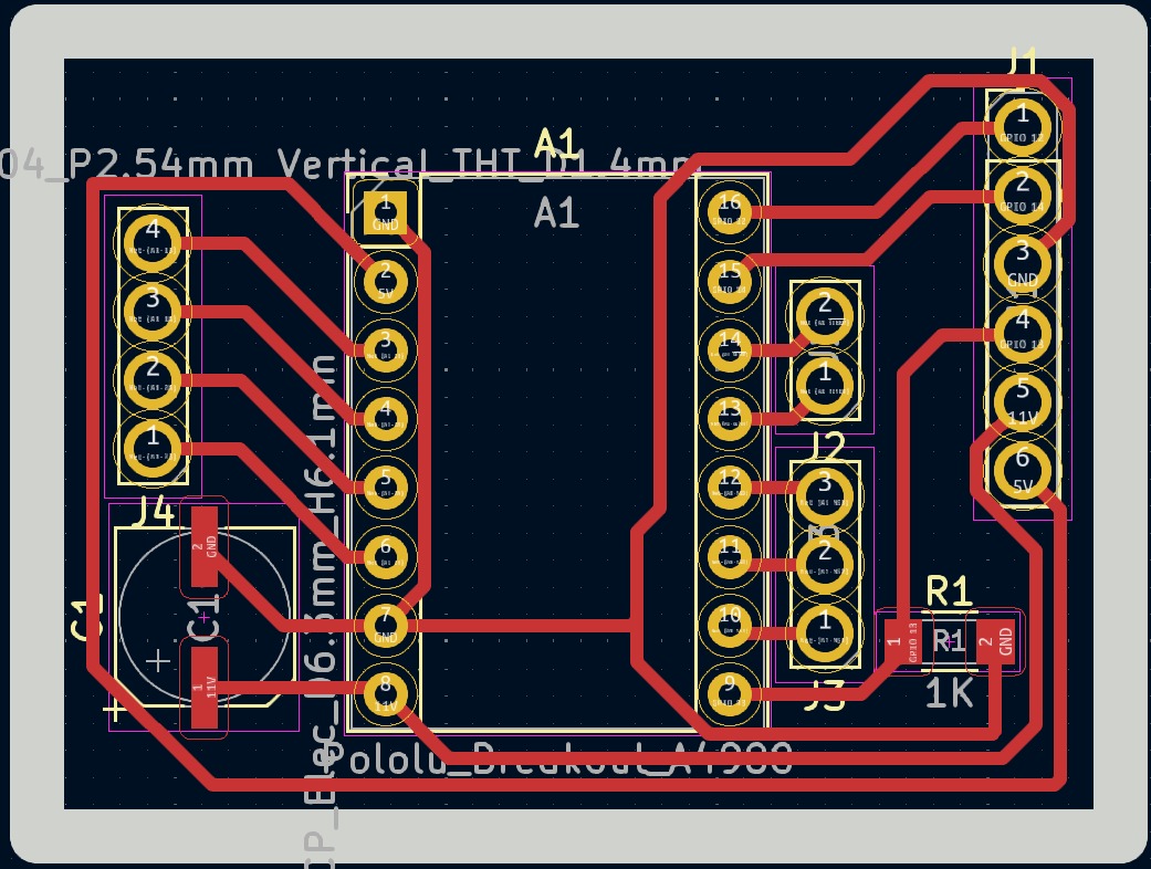
And here is the XIAO PCB
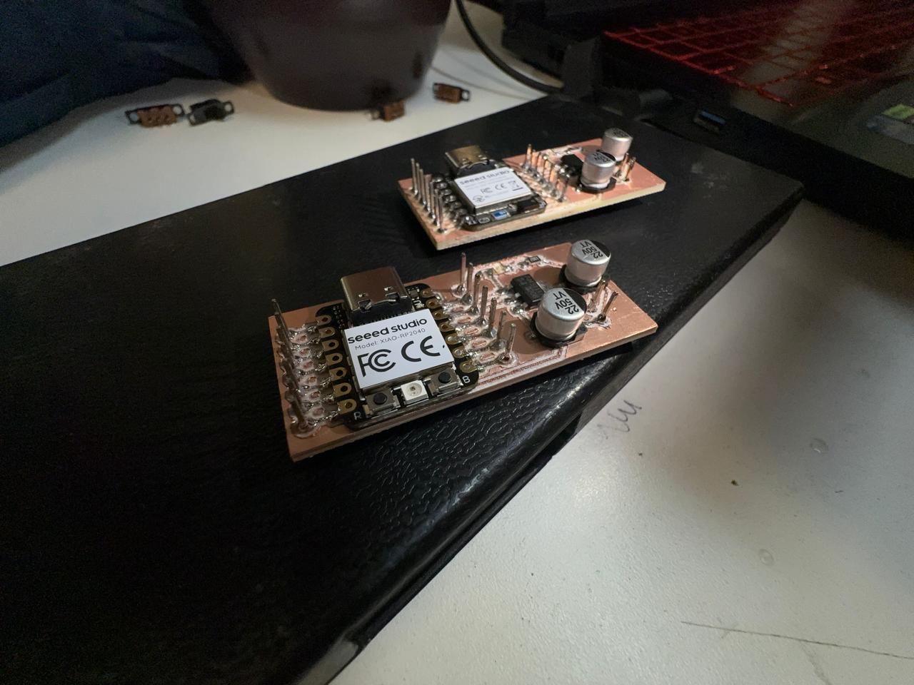
Here is the schematic for the XIAO PCB
Files
week 11
I sent the XIAOnRF52840´s accelerometer data via bluetooth to the ESP32
I changed my mind on how I will be making the card, dispenser. One of my friends at the Fab gave me the idea of making the dispenser like a Carousel, where a motor turns the card stacks form each categories, and with another motor push the correct card stack out, so the players can pick the card.
week 13
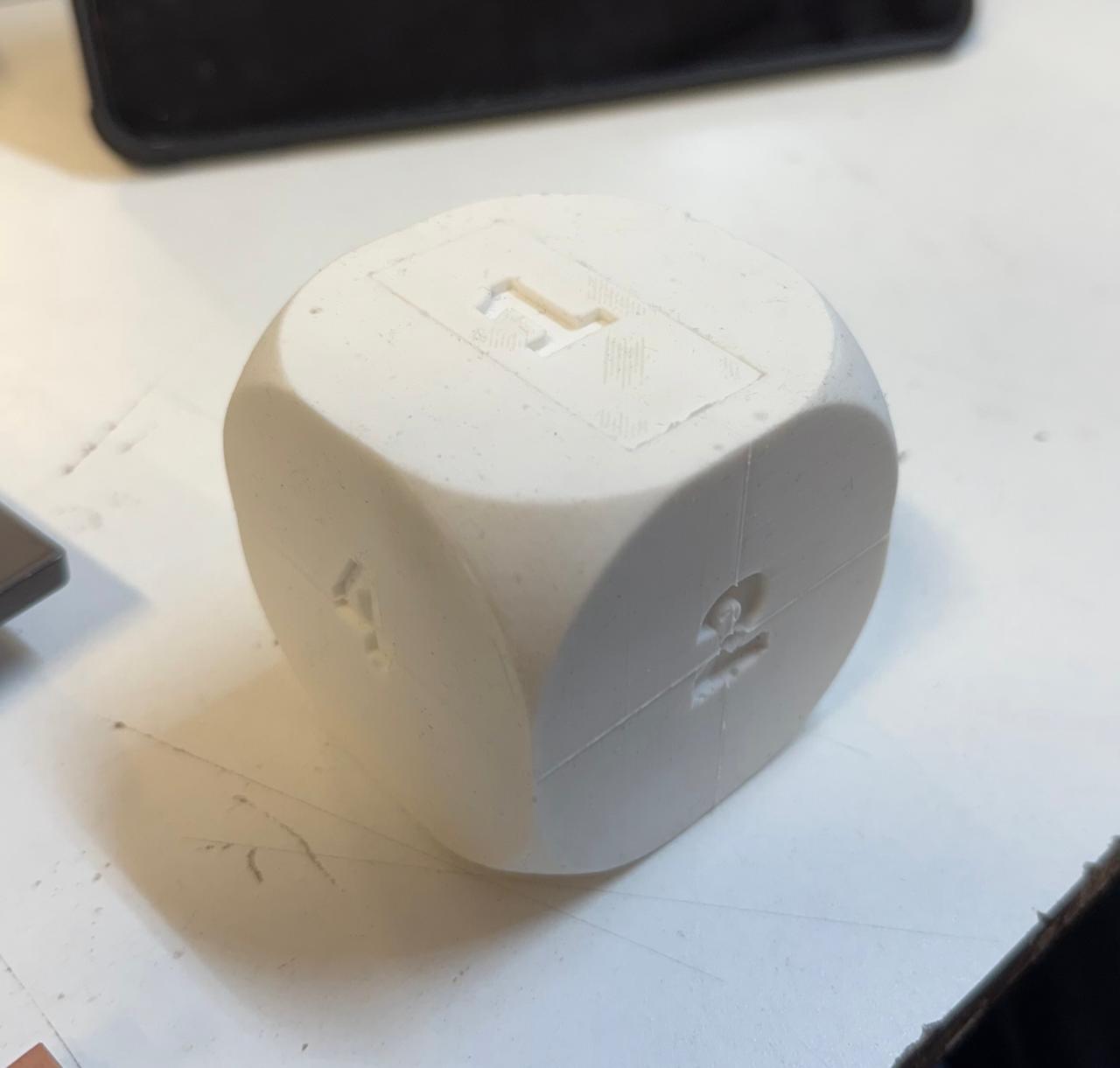
I made a mold to make a die, I used silicone instead of the original plan of an MFD die with soft corners.
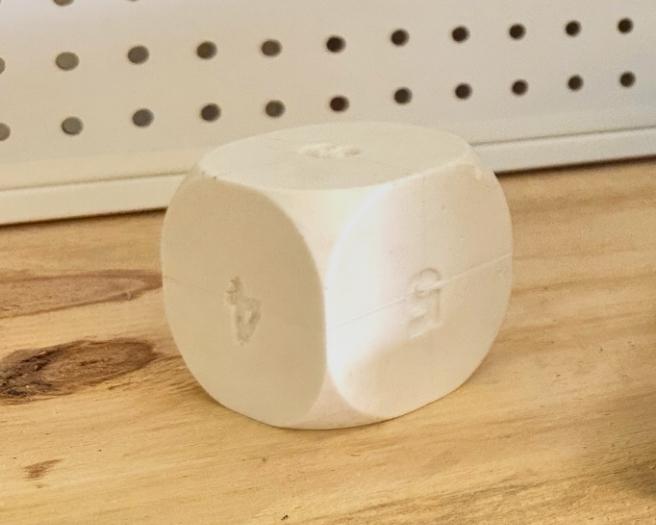
The die has a square hole so i can fit the XIAOnRF52840 that i will be using.
Files
Mechanism
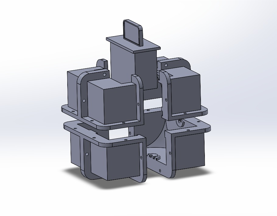
I started sketching the mechanism for the card dispenser since the very beginning, but I wasn´t fully convinced of the design. I wanted to make a mechanism that used as few motors as possible, so I could keep the cost down. I did started designing a mechanism that could work like a carousel, where a stepper motor would turn the card stacks, and a DC motor with an encoder would push the correct stack out:
After some testing, I realized that the mechanism was too big, so I started designing a new one.
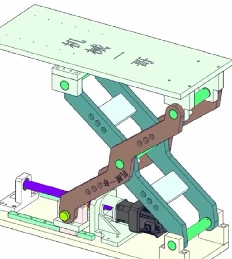
I based the pushing mechanism is this photo that I found:
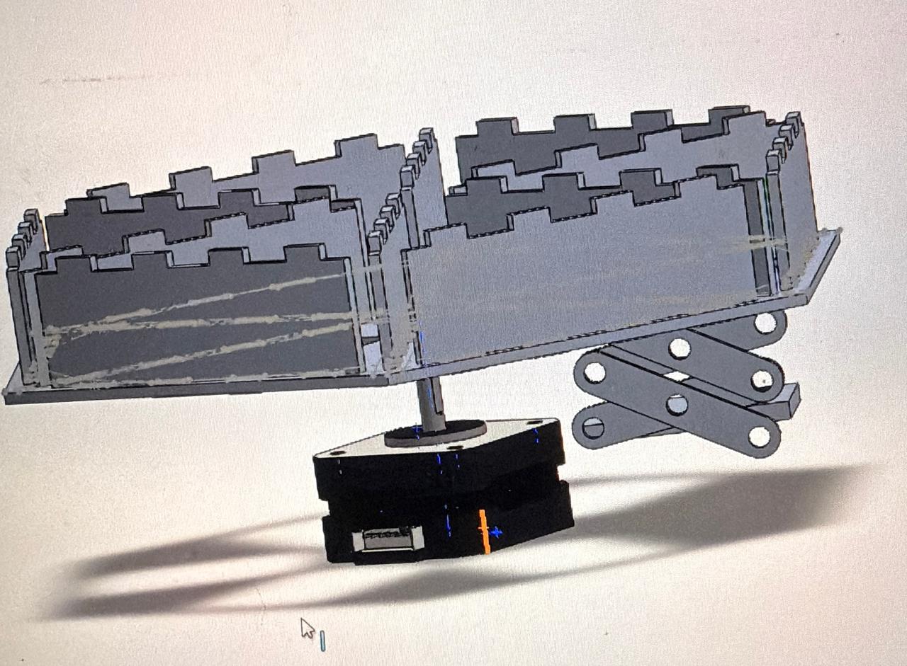
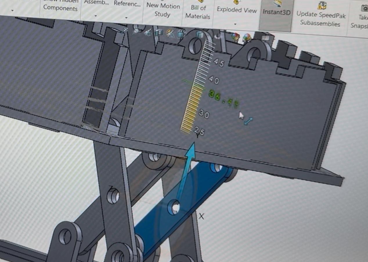
I started by checking the length and number of bars each bar needed to be so the mechanism could elevate to the required height.I made an assembly on SOLIDWORKS to see its behavior.
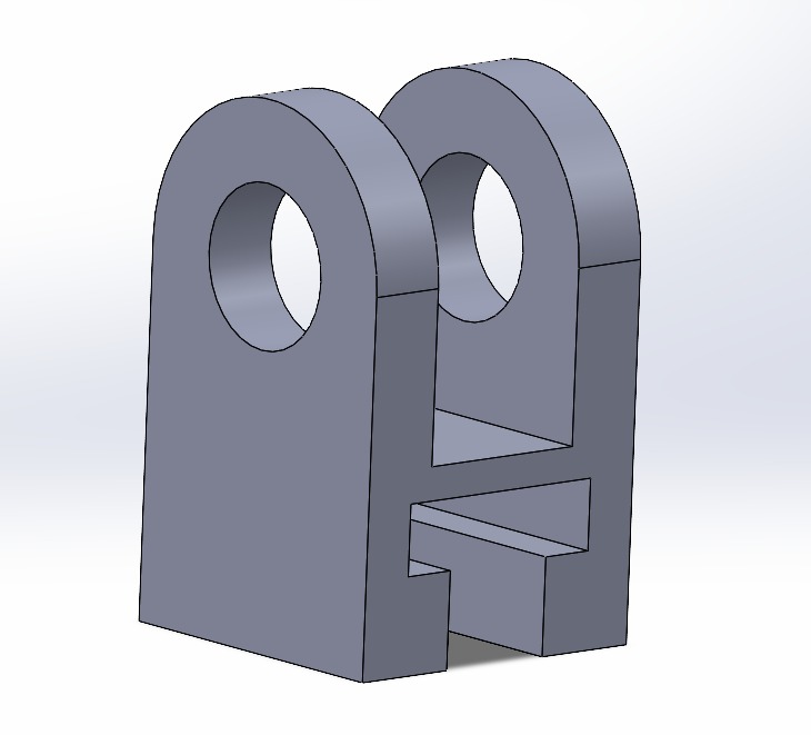
After I had the right measures I had to design a "rail" or something where the scissor mechanism could slide. So I made two pieces and I printed them to see if they could slide properly:
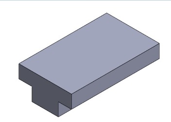
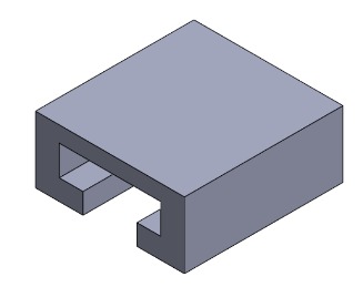
I made some adjustments to the tolerance between the pieces and I designed the parts that would fit together:
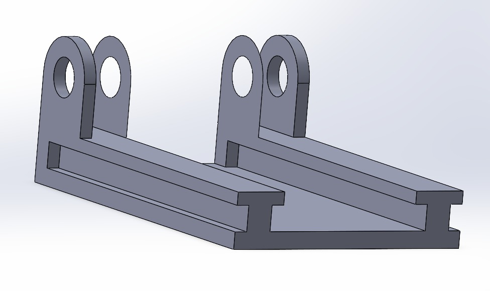
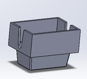
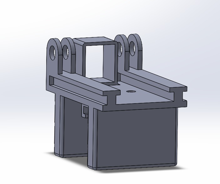
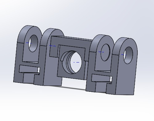
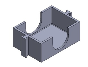
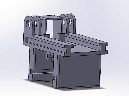
After I had the essential parts of the mechanisms, I made a bottom part which would hold the motor and a top part that would push the card stacks out. I made the top part with a square hole so it could fit the card stacks box in it.
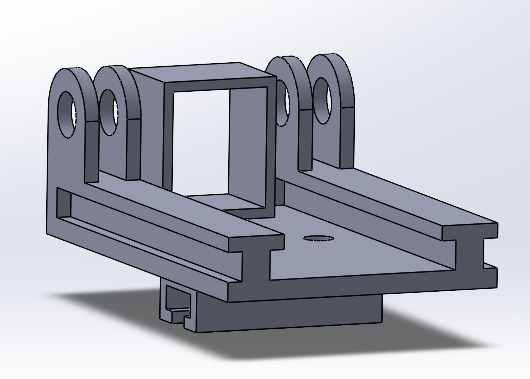
I design a way to screw and hold a timing band into that part.
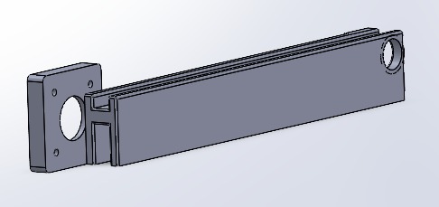
Instead of making a carousel I decided to make it linear, so the pushing mechanism had to be moved sideways. I designed a piece that would hold the stepper motor which would have a pulley with timing band that would move the pushing mechanism.
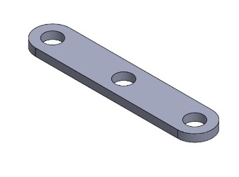
Before printing these parts I figured out a way to assemble the scissor mechanism, I didn´t wanted to use screws, so I designed two pieces that would hold the bars together.
Once I printed these parts I put them together and I tested it.
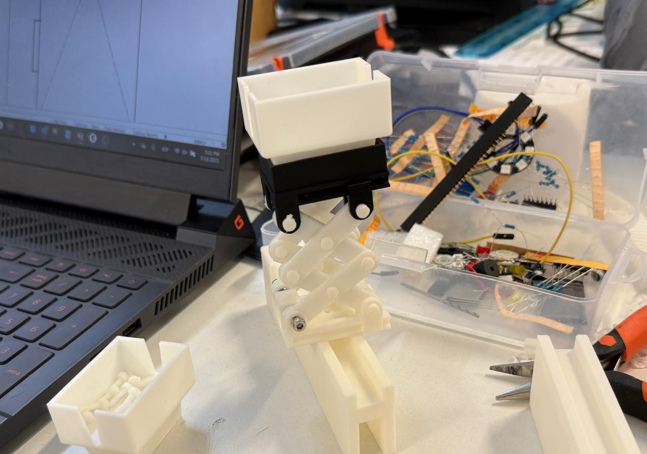
I also made some card holders:
After some tests I realized that the base I made for the push mechanism had some stability issues so I added some guides to the side:
Now it was working properly:
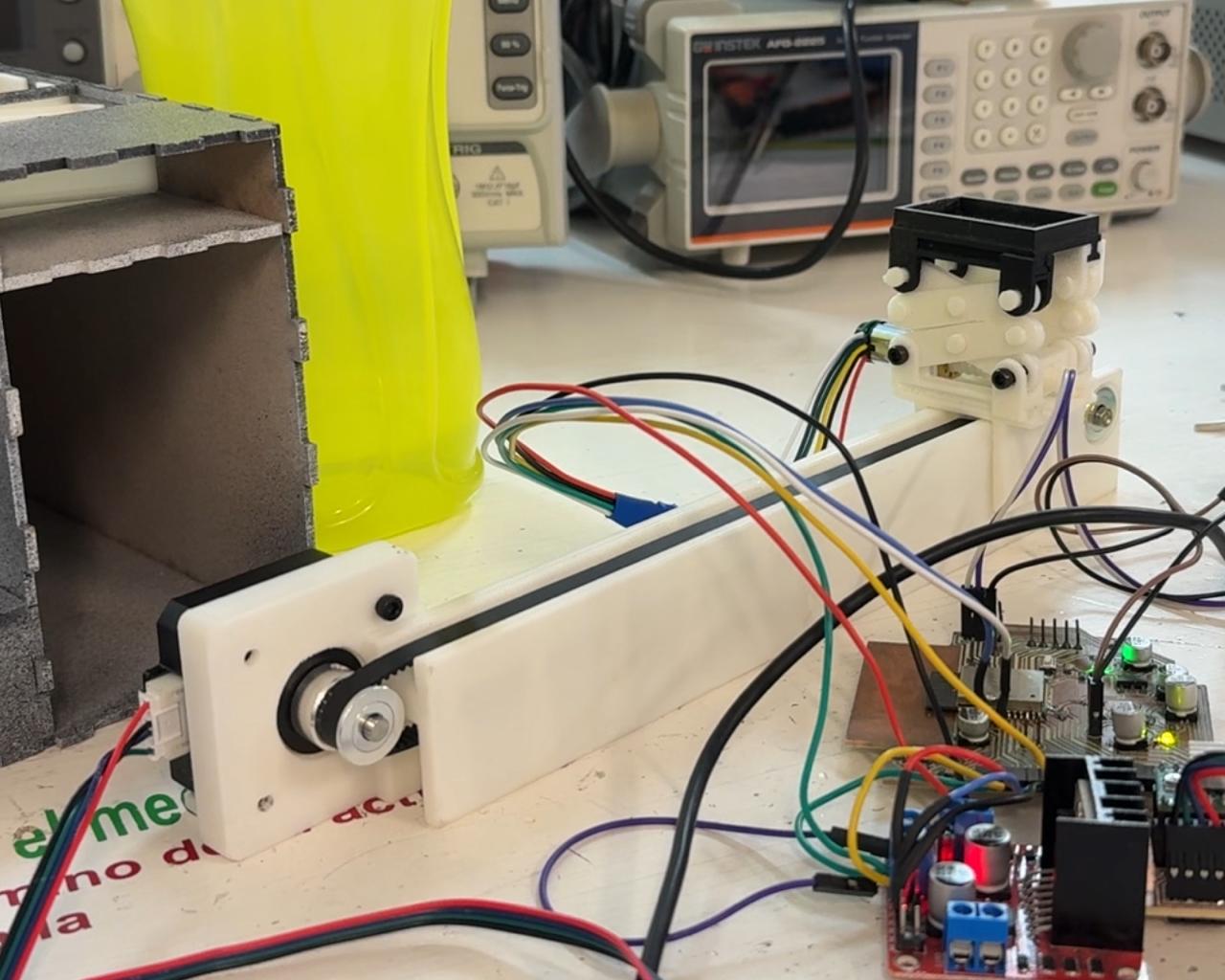
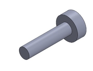
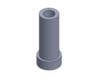
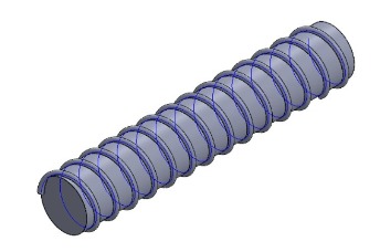
To move the scissor mechanism I made a threaded spindle that is connected to a DC motor.
I also made a sort of nut that is attached to the scissor mechanism, so when the threaded spindle rotates the nut moves two of the bars of the scissor mechanism back and forth so the top part goes up and down.
I made the proper testing and everything worked properly
week 15 System integration
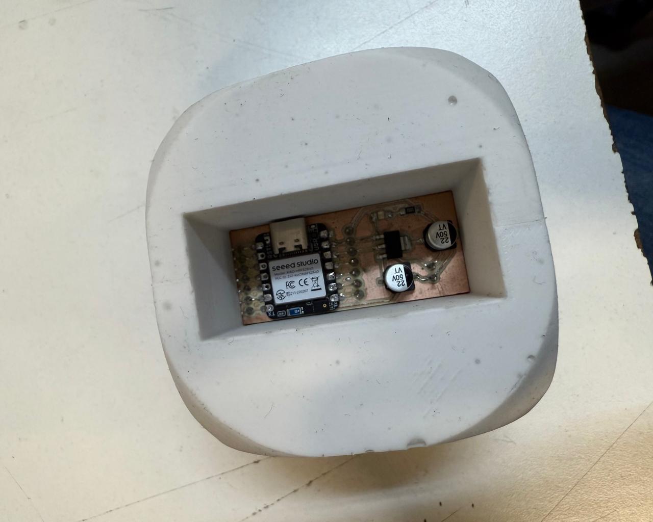
I´m still designing the mechanism for my final project, but I already have taken some design considerations for better integration. For the Die I made from silicone, I designed the mold with the correct dimensions to fit a PCB with the XIAO nfr52840 from which I´ll use the accelerometer:
After finishing the die, I started designing the mold. I was planning to put a XIAO nfr52840 inside the die, so I needed to be able to remove a face to insert the board. I opened a copy from my die to make some modifications.
To make the hole I measured the PCB I built for the board:
I considered a 54x24mm square so it could fit easily.
I extruded the face containing number one from the die:
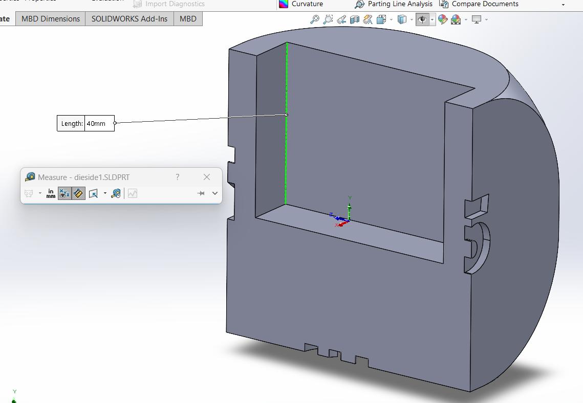
The hole I made is a little over half the die´s height, so I can place the board at its center.
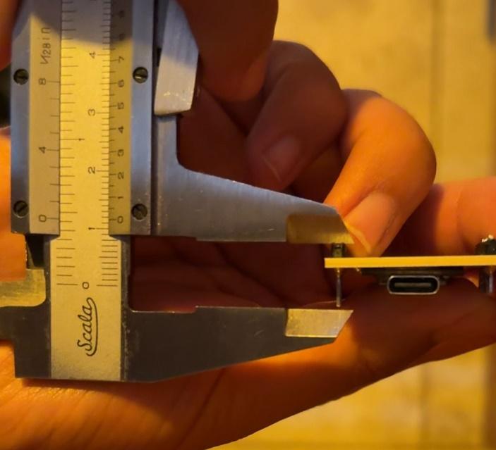
I measured the PCB´s height to make sure I left the right amount of space.
The XIAO fits perfectly inside the die:
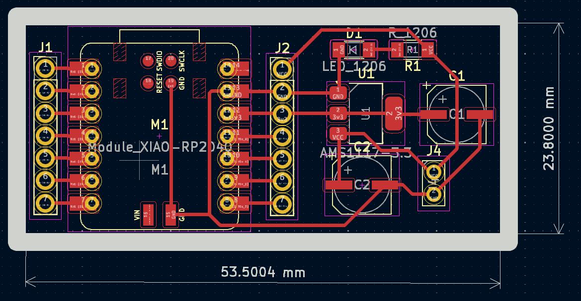
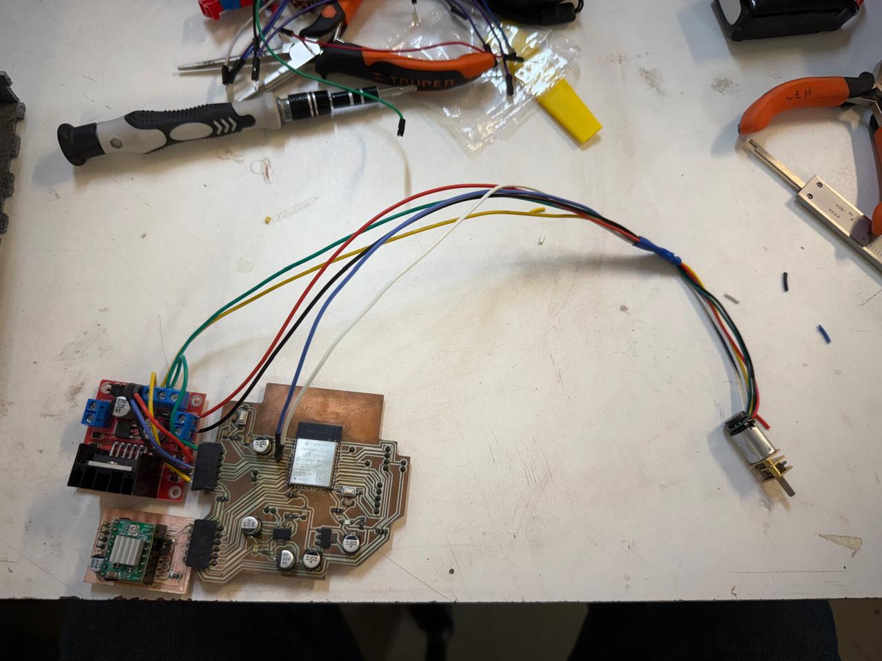
The mechanism I´m going to build for the cards will be controlled with an ESP32. To do so, I´ll use a small DC motor with an encoder and a stepper motor. During week 6 I designed the PCB for the ESP32 keeping in mind the connections I would need for the motors. I also designed the PCB for the stepper motor driver. These two PCBs are designed to be connected flawlessly.
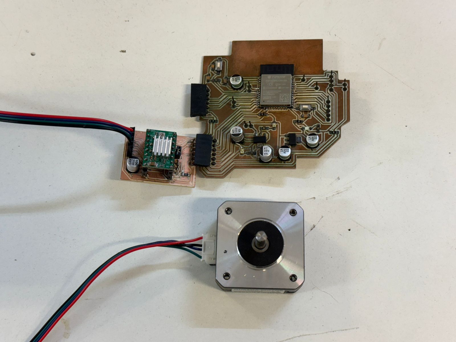
This design allowed me to connect both PCBs directly and I just needed a cable for the stepper motor which looks cleaner.
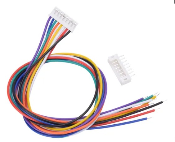
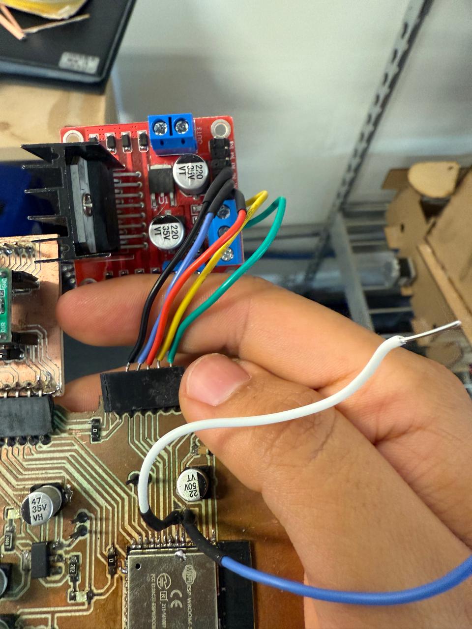
On previous weeks (week 10 and week 14) I´ve used a small DC motor with an encoder. Although I´ve successfully controlled the motor with an ESP32, The connection between the motor and the PCB is not ideal, because I use jumper wires to connect the motor to the PCB. I´m planning to use a Jst pin connector to make the connection more reliable and to look cleaner.
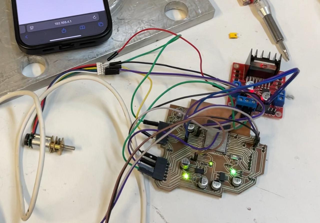
Messy cables
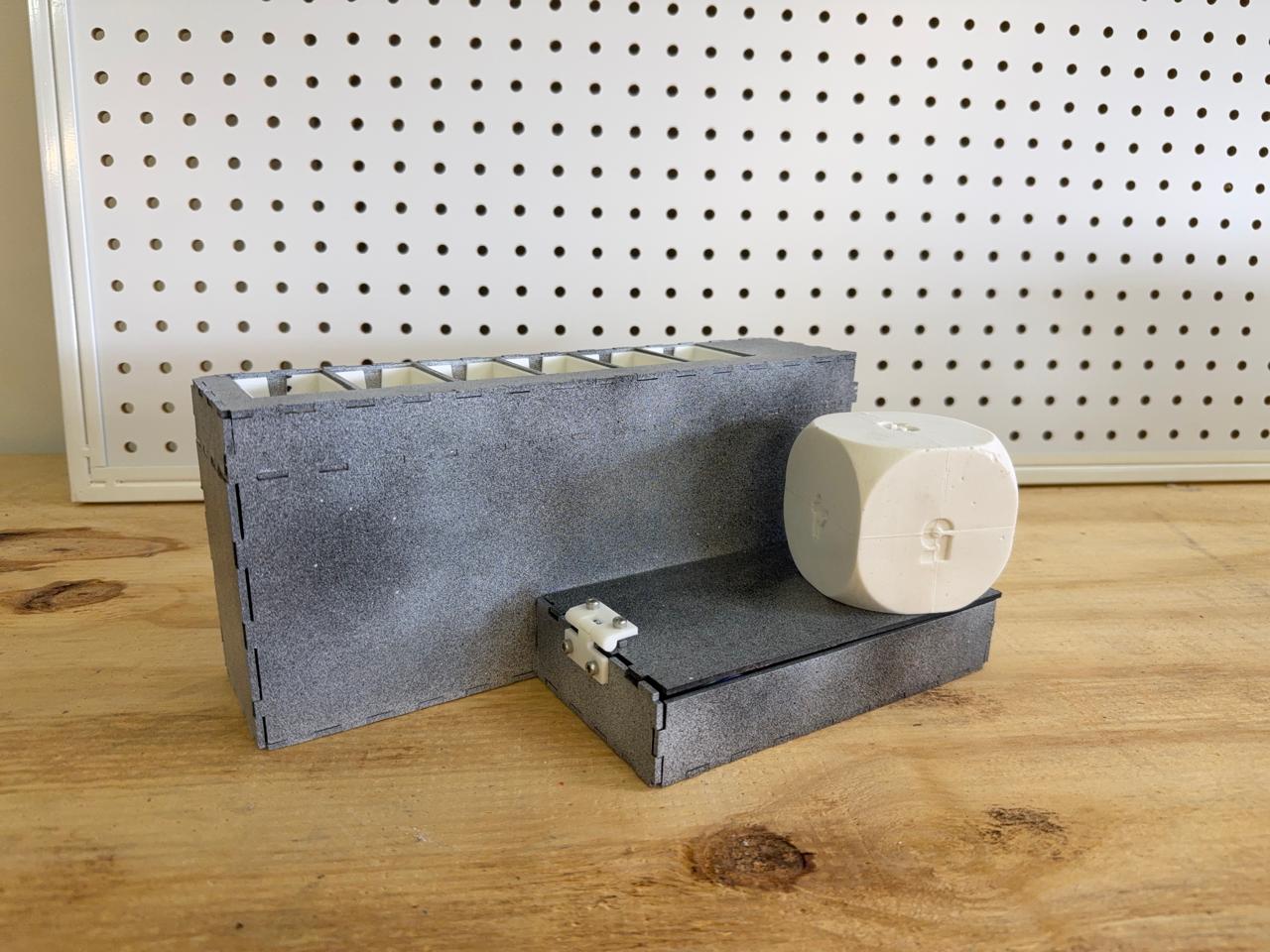
My final project is not intended to be a sold product, it´s more of a personal project which I plan to use with my brother, friends and family, so I´m not making a packaging for it, but I´m trying to make it look as good as possible and to be easy to travel with. What I´m trying to do is to make a box/base that can hold the die and the card dispenser.
Final Steps
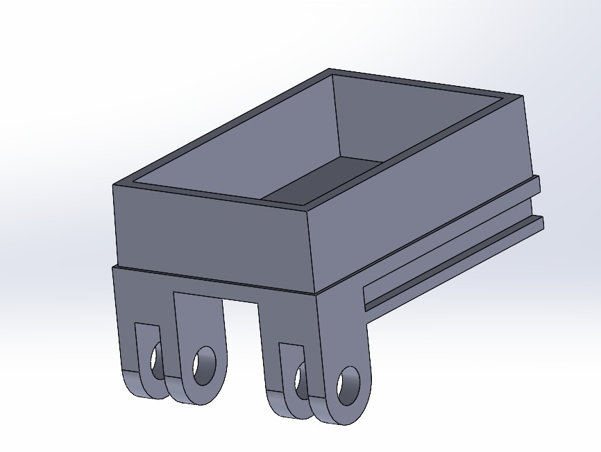
I started designing the box that would enclose the mechanism.
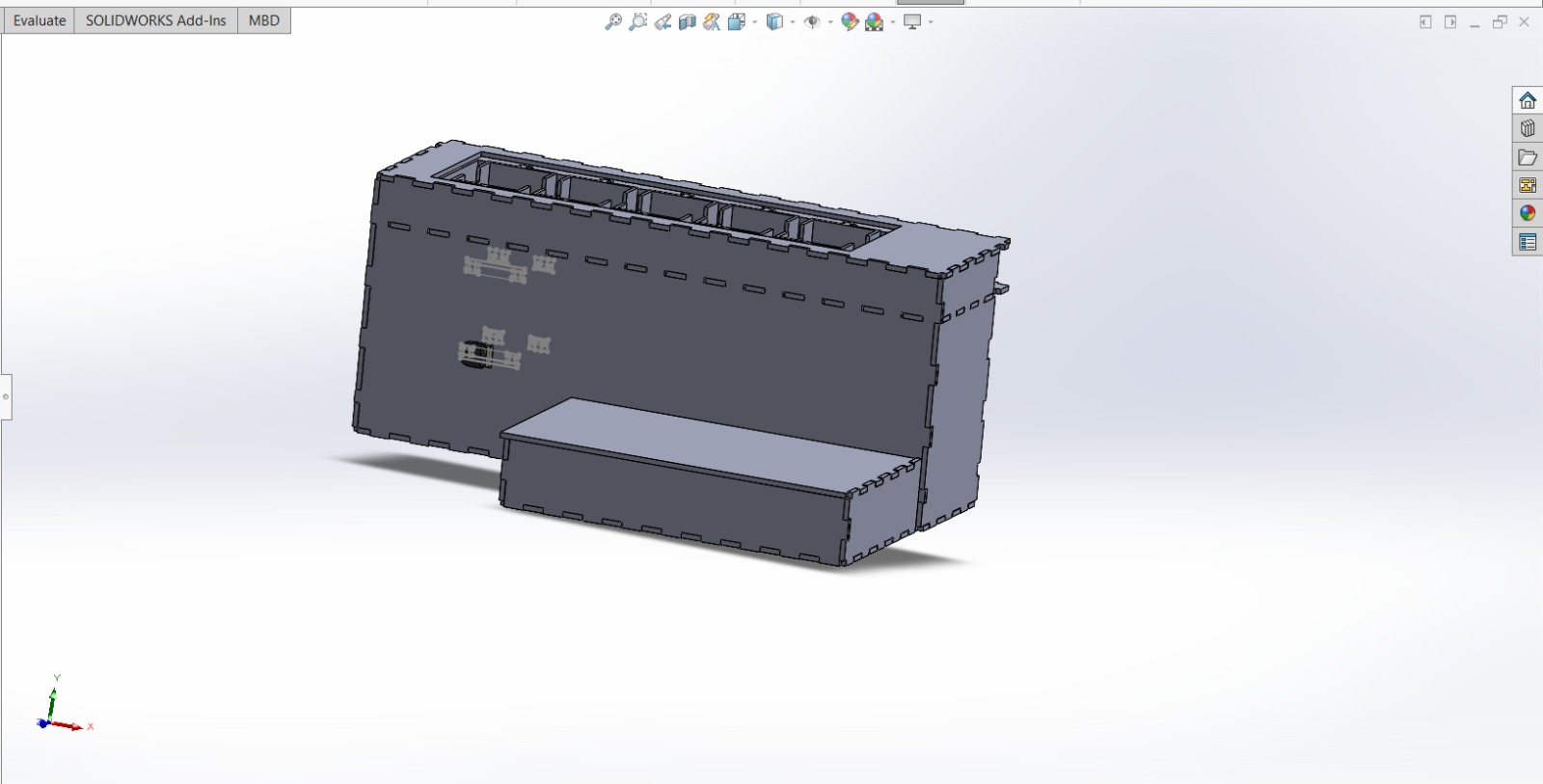
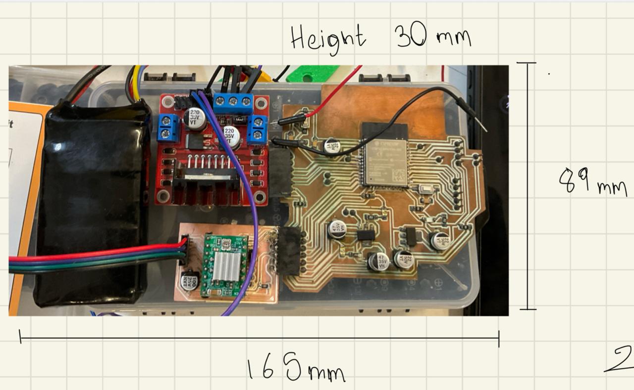
On the back of the mechanism I added a small box to fit all the electronics
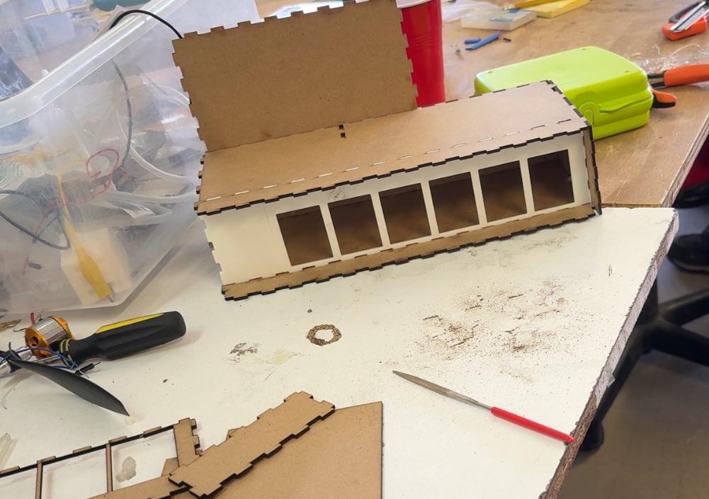
I laser cut the box and assembled it.
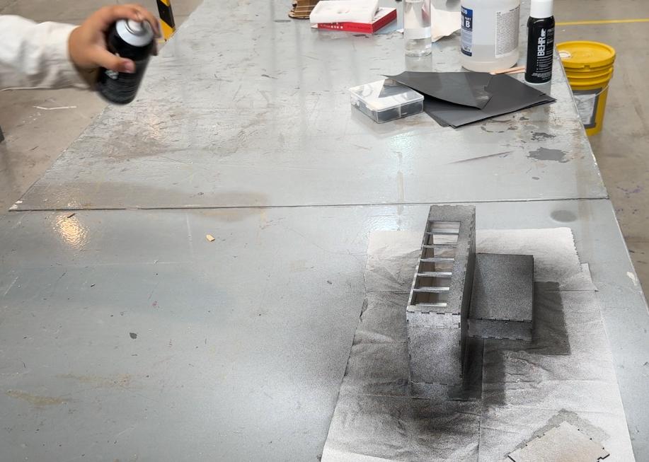
Then I painted it to make it look better:
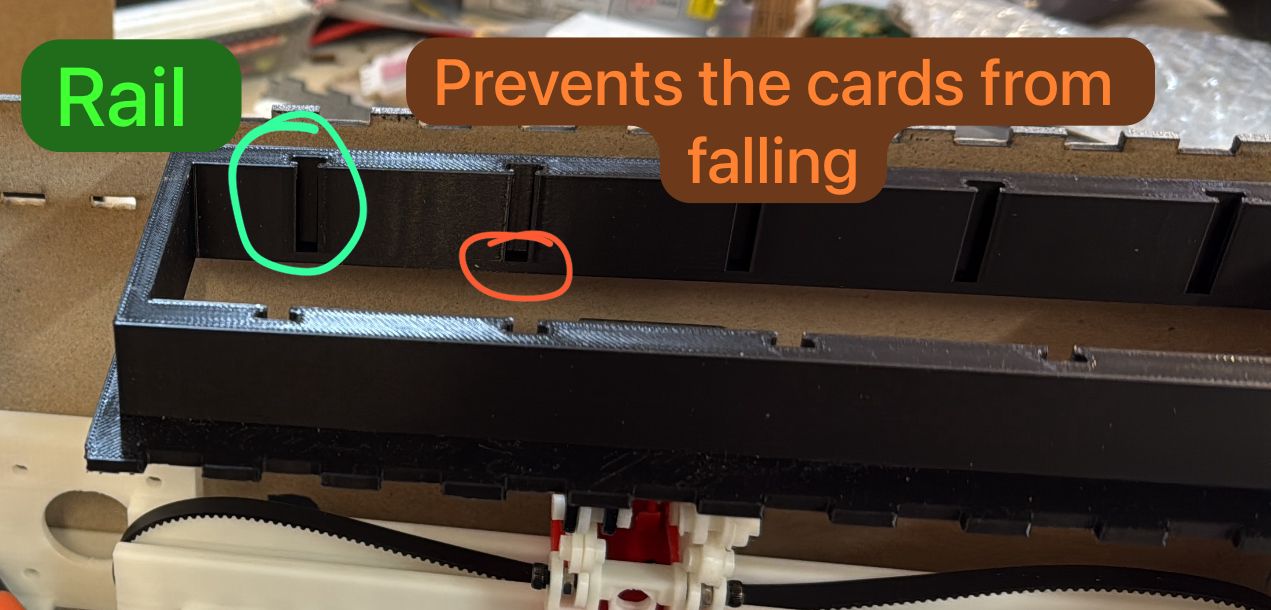
I made a "frame" where the card holders would sit and be pushed easily, but after making some tests I realized that me mechanism could get stuck if the card holders were not perfectly aligned, so I had to redesign this part so it could hold them in place and don´t get stuck.
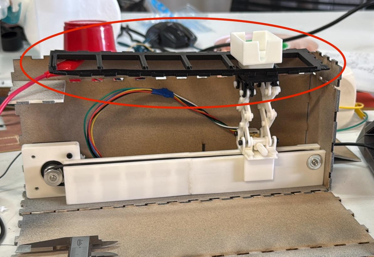
I came up with the idea of making a "rail" where the card holders would slide, so I designed a piece that would hold the card holders in place and allow them to slide. I also modified the card holders so the could follow the rail.
Now that it was working properly, I started wired the DC motor properly:
I tested how the wires interacted with the whe mechanism´s movement and they were too stiff so I changed them, I also made some changes to the mechanism to make it more stable since the wires made the "elevator" to tilt.
I added more rails to the mechanism, this time to the longest part I had which hold the stepper motor, and some guides for the base of the elevator.
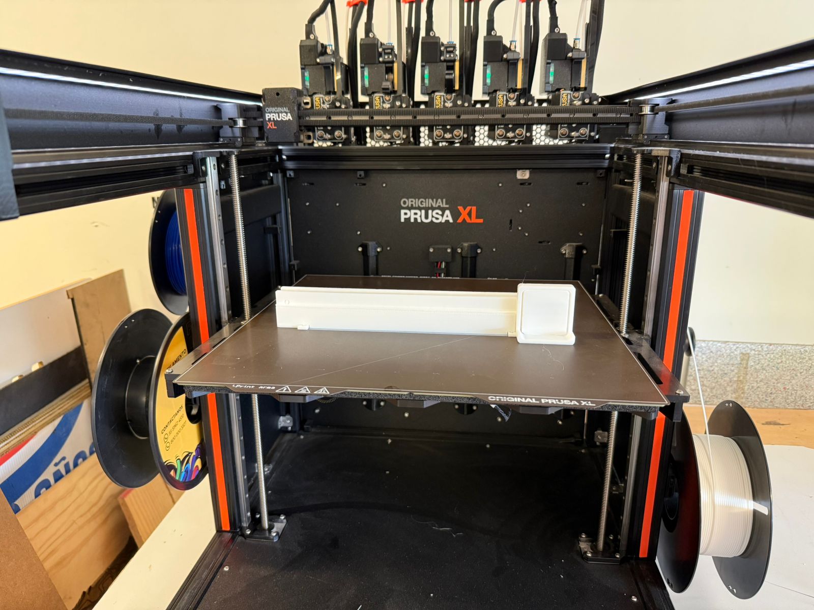
I made extra modifications to the longest part, and I used a PrusaXL to print it in a single piece.
Code
I tested all the mechanism with a simple code I had. I used the serial monitor to send the amount of steps/pulses to move each motor in both directions. You can download the code here.
Once I had the mechanism working properly I made the final version of the code, during week 11 I made a code that allowed me to send the accelerometer data from the die to the ESP32, on week week 10 I made a code that allowed me to control the DC motor with an encoder. With the last code I made I had also the stepper motor controlled, so I just had to combine the codes and add the logic to make the mechanism work properly.
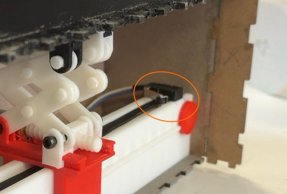
To make the programming easier I added a limit switch on the opposite side of the mechanism so I could detect when the elevator reach the end.
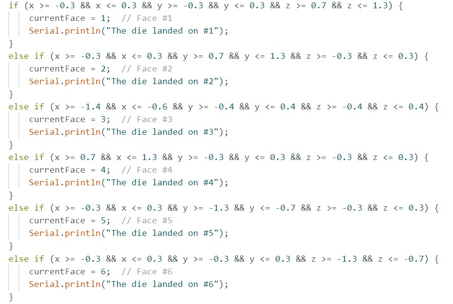
First I had to get the right logic to accurately detect on with face the die landed. I made some tests with the XIAO´s accelerometer to see how the data behaved depending on its position, I used the serial monitor to see the data and I added a simple logic to the code to detect the face.
It detected each face accurately but it couldn´t detect when the die stopped moving, after some research I discovered that I could use the gyroscope to detect when the die stopped moving, so I added the logic to receive and detect when the gyroscope data had low values. On the XIAO I activated the sensor and send the data via Bluetooth to the ESP32.
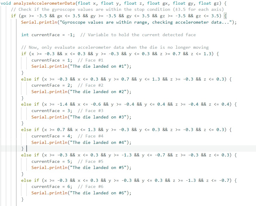
With this logic I could detect when the die stopped moving and which face was on top, so I could trigger the motor´s motion.
After I had the logic working, I added the code to control the motors, I used the limit switch to detect when the elevator reached the "origin", so I could stop the stepper motor, move it into the other direction the right amount of steps to reach the right card stack, and then trigger the DC motor to push the card stack out.
Here are the final codes:
Here is a video of the final mechanism working:
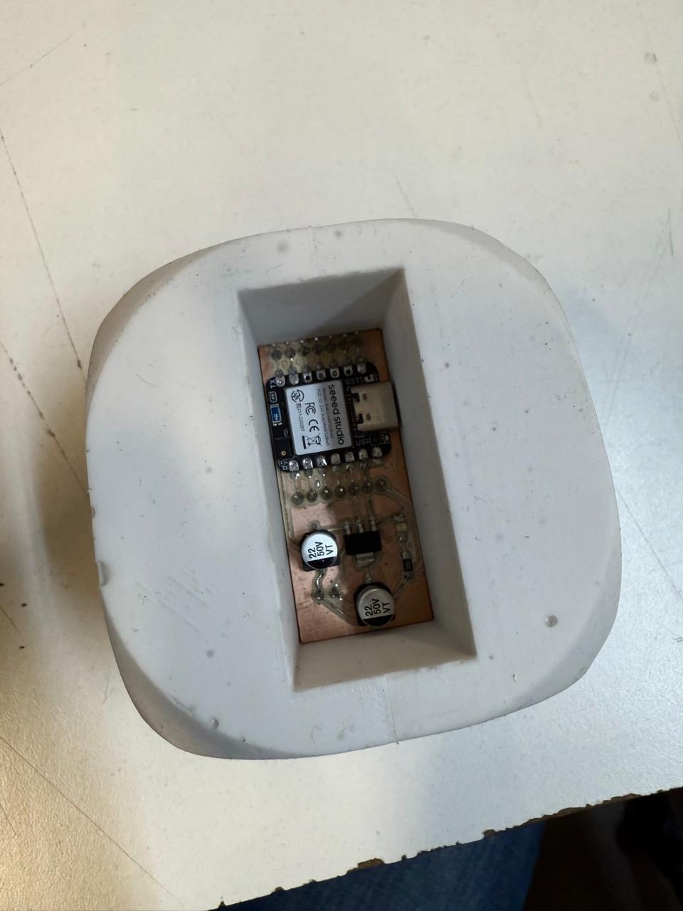
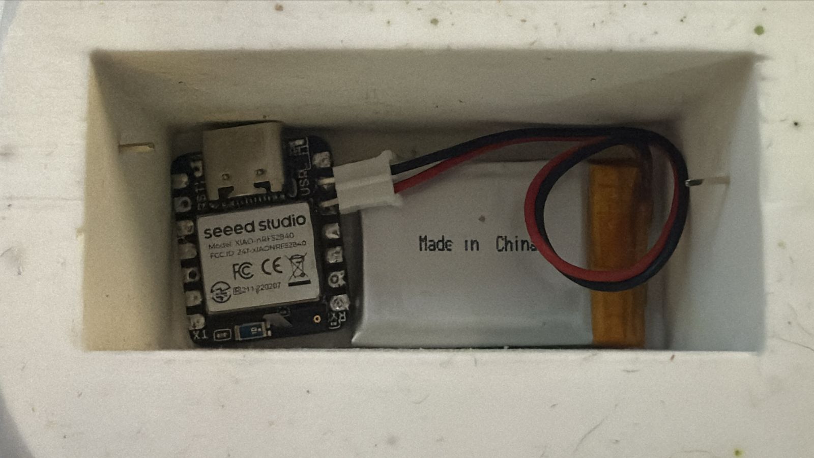
I realized that I didn´t need a PCB for the XIAO, thus the capacitors fell apart when I was making some durability tests, so I just used the XIAO with some male pins to connect it to the LiPo batery.
I tested everything worked properly, I trowed the die several times to see that the faces got detected accurately.
Files
You can download all the files I made on SOLIDWORKS:
All the files are .step so I was able to compress them and put them here.
Week 17 Applications and Implications
Charades is a classic game of silent acting and guessing that traces its roots to 18th-century France, where it began as a literary riddle game. It later evolved in 19th-century England into a familiar performance-based version, in which players mime words or phrases for others to guess. Over time, charades became a popular parlor game and party activity worldwide, known for encouraging creativity, teamwork, and quick thinking without speaking. “Charades – The Game" by John N. Hansen Co. is a boxed version created by The John N. Hansen Company, an American manufacturer and distributor of games, toys, and puzzles since 1952. The company's edition takes the traditional format and adds structure, like a custom die to determine categories (Movies, Songs, TV, etc.). Clue cards with curated titles. And a sand timer for the 60-second round.
My project is mainly based on this board game. But also inspired by a TV show that my little brother enjoys watching. The TV show has a slightly different use of the die. Instead of being used to select a category, it dictates a challenge or a special situation, like acting with their mouth filled with water.
The project will include a “smart die”, which was made from silicone during the molding and casting week, inside of it an XIAOnrf52840 sense will be used to send the accelerometer´s data into the “card dispenser”. The dispenser will have an ESP32 WROOM 32 soldered into a custom PCB, which will receive the data via Bluetooth and will control the mechanism. The mechanism will be 3D printed (additive fabrication). And it will be contained inside a Medium-Density Fiberboard box, the box will be made using a laser cutter (subtractive fabrication). I designed the custom PCB using KiCAD, and I made the 3D models of the dispenser using SOLIDWORKS. The box was designed using SOLIDWORKS as well.
Bill of Materials
| Custom PCB Components | Custom PCB Components | Custom PCB Components | Custom PCB Components | Custom PCB Components |
| Item | Details | Quantity | Unit Price | Source / Link |
| ESP32-wroom32 | - | 1 | $4 | link |
| 0.1uF capacitor | 1206 smd | 4 | - | - |
| 22uF capacitor | 6.3x6.1 mm smd | 5 | - | - |
| 2k resistor | 1206 smd | 2 | - | - |
| 10k resistor | 1206 smd | 1 | - | - |
| LED | 1206 smd | 3 | - | - |
| 0 resistor | 1206 smd | 4 | - | - |
| 6x3.5 mm button | - | 2 | - | - |
| Female pin | - | 10 | - | - |
| Male pin | - | 21 | - | - |
| AMSL117 3.3v regulator | - | 1 | - | - |
| AMSL117 5v regulator | - | 1 | - | - |
| Mechanical Components | ||||
| PLA filament | - | ~300g | $5 | link |
| 3M Screws | 10mm | 11 | - | - |
| Timing band | - | ~40cm | - | - |
| Pulley for Nema 17 | - | 2 | - | - |
| 3M hex nuts | - | 6 | - | - |
| Electronic Components | ||||
| Nema17HS4023 Steper motor | 12v | 1 | $10 | link |
| Lithium Polymer Batery | 3.7v 250mAh | 1 | $10 | link |
| DC motor with encoder | 6v | 1 | $12 | link |
| 3-cell 750 mAh LiPo batery | 11.1v | 1 | $17 | link |
| Multiple color wires | - | 6 | - | - |
| A4988 stepper driver | - | 1 | $3 | link |
| L298N motor driver | - | 1 | - | - |
week 18 Invention, Intellectual Property and Income
I´m not planning on selling my project, since the beginning it was thought of as a gift for my brother, or at least something we can play with family. Nonetheless, I think it is worth registering it as an idea. I entered the Creative Commons website to do so.
I didn´t know which type of license to choose, but the website was easy to use and gave me a recommendation after filling in some information.
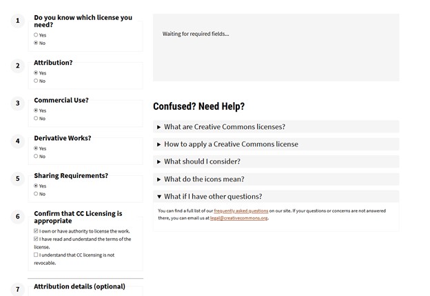
Now my project is licensed as follows:
Roll the Role © 2025 by Leonardo Zamora Hernández is licensed under CC BY-SA 4.0This license requires that reusers give credit to the creator. It allows reusers to distribute, remix, adapt, and build upon the material in any medium or format, even for commercial purposes. If others remix, adapt, or build upon the material, they must license the modified material under identical terms.
Future Possibilities
At this moment, I do not intend to sell this for profit, nonetheless, that might change in the future. My project is easy to replicate with a few machines needed for its fabrication. I would need a 3D printer for the mechanism, a laser cutter for the box, and a milling machine for the PCB. The parts were designed in such a way that they don´t require advanced mechanical manufacturing processes. The Die is made from a mold, so it can already be mass-produced.
I could make the mechanism much smaller so the box can be shorter and narrower. I could use a different board for the die dispenser, so the PCB gets a smaller footprint. And even add more elements to make it more colorful and eye-catching, like LEDs to the box, and maybe change the die´s size.
Final Video and Slide
I uploaded a draft of my final presentation slide and video, and I checked on my website and the Fab´s website as well.