10. OUTPUT DEVICES
This week, I created a code to move a DC motor for my final project. We also did a group assignment, which you can find here.
Motor and Encoder Setup
I bought a Gear Motor with a Magnetic Coded Disc Hall Encoder. This encoder is a rotary encoder that uses a Hall effect sensor to detect the position of a magnet attached to the motor shaft. The encoder generates two square wave signals, A and B, which are 90 degrees out of phase with each other. By analyzing these signals, we can determine the direction and speed of the motor's rotation.
Control System
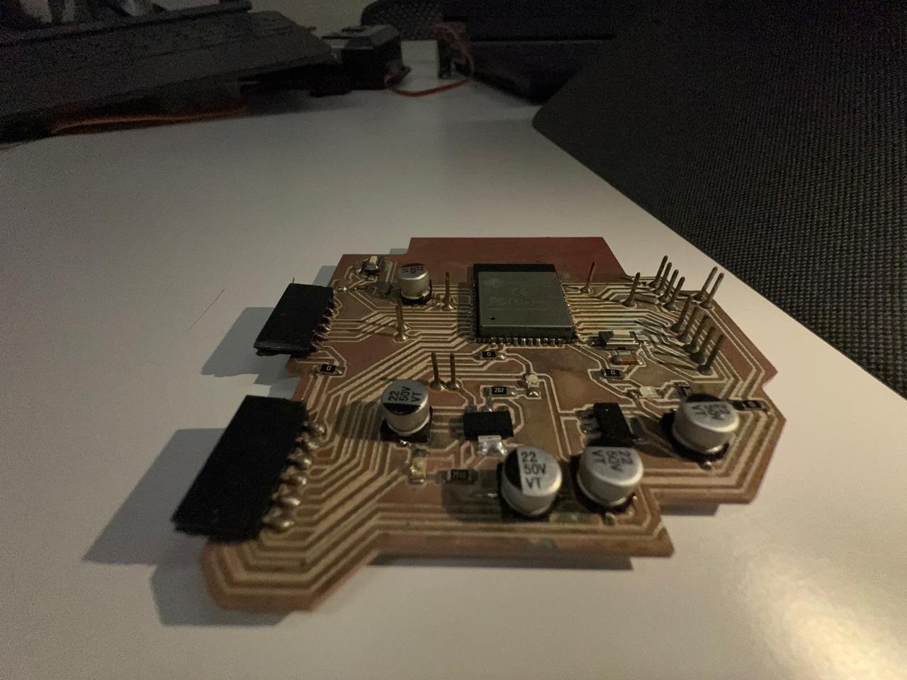
To control the motor, I used the ESP32 PCB I made on week08 and a L298N motor driver. The motor driver allowed me to control the direction of the motor using a signal from the ESP32. The code I wrote reads the encoder signals and moves the motor in both directions. This way, I can achieve precise control over the motor's position and speed.
Wiring the Motor
Before coding, I checked out the pinout of my motor to learn how to connect it. I bought this motor on Amazon, so I scrolled down the product information until I found the pinout:

This information was useful to know how my motor works. The motor I received had different colors. After some research, I found out how to wire my motor:
- red: motor power-
- black: motor power+
- yellow: encode power +
- green: encode power --
- blue: encode output A phase
- white: encode output B phase
I connected the red and black cables to OUT1 and OUT2 from the driver, the yellow cable to 3.3V, the green one to ground, and the blue and white cables to 2 pins from the ESP32 to send data. I also connected the IN1 and IN2 from the driver to 2 pins from the ESP32.
Encoder Reading Code
I didn't know how to read the data from the encoder, so I asked Chat GPT how to do it. Here's the code it gave me:
void updateEncoder() {
    int MSB = digitalRead(encoderPinA); // Reads the pin A state (blue)
    int LSB = digitalRead(encoderPinB); // Reads the pin B state (white)
    int encoded = (MSB << 1) | LSB; // transforms the state into a binary number
    int sum = (lastEncoded << 2) | encoded; // Combines with the previous state

    if (sum == 0b1101 || sum == 0b0100 || sum == 0b0010 || sum == 0b1011) {
        pulseCount++; // Increments the counter if the motor spins in a direction
    }
    if (sum == 0b1110 || sum == 0b0111 || sum == 0b0001 || sum == 0b1000) {
        pulseCount--; // Decrements the counter if the motor spins in the opposite direction
    }
    lastEncoded = encoded; // Saves the last state
}
Final Implementation
Here's the final code I uploaded to my ESP32:
// Pin definitions
const int in1Pin = 12; // Connect to IN1 pin of H-Bridge
const int in2Pin = 13; // Connect to IN2 pin of H-Bridge
const int enAPin = 14; // Connect to ENA pin of H-Bridge (PWM)
const int encoderPinA = 34; // Connect to Blue wire (A)
const int encoderPinB = 35; // Connect to White wire (B)

// Variables to store pulses
volatile int pulseCount = 0;
int lastEncoded = 0;

void setup() {
    Serial.begin(115200);

    // Configure pins as outputs
    pinMode(in1Pin, OUTPUT);
    pinMode(in2Pin, OUTPUT);
    pinMode(enAPin, OUTPUT);

    // Configure pins as inputs
    pinMode(encoderPinA, INPUT);
    pinMode(encoderPinB, INPUT);

    // Configure interrupts to detect pin changes
    attachInterrupt(digitalPinToInterrupt(encoderPinA), updateEncoder, CHANGE);
    attachInterrupt(digitalPinToInterrupt(encoderPinB), updateEncoder, CHANGE);
}

void loop() {
    // Rotate in one direction
    digitalWrite(in1Pin, HIGH);
    digitalWrite(in2Pin, LOW);
    analogWrite(enAPin, 200); // Speed (0-255)
    delay(2000); // Rotate for 2 seconds

    // Stop the motor
    digitalWrite(in1Pin, LOW);
    digitalWrite(in2Pin, LOW);
    delay(1000); // Pause for 1 second

    // Rotate in the opposite direction
    digitalWrite(in1Pin, LOW);
    digitalWrite(in2Pin, HIGH);
    analogWrite(enAPin, 200); // Speed (0-255)
    delay(2000); // Rotate for 2 seconds

    // Stop the motor
    digitalWrite(in1Pin, LOW);
    digitalWrite(in2Pin, LOW);
    delay(1000); // Pause for 1 second

    // Print the pulse count
    Serial.println(pulseCount);
}

void updateEncoder() {
    int MSB = digitalRead(encoderPinA); // Read pin A state (Blue)
    int LSB = digitalRead(encoderPinB); // Read pin B state (White)
    int encoded = (MSB << 1) | LSB; // Convert states to binary number
    int sum = (lastEncoded << 2) | encoded; // Combine with previous state

    if (sum == 0b1101 || sum == 0b0100 || sum == 0b0010 || sum == 0b1011) {
        pulseCount++; // Increment counter if motor rotates in one direction
    }
    if (sum == 0b1110 || sum == 0b0111 || sum == 0b0001 || sum == 0b1000) {
        pulseCount--; // Decrement counter if motor rotates in opposite direction
    }
    lastEncoded = encoded; // Store last state
}
Project Showcase

In the video, you can see the motor rotating in both directions. The encoder is working correctly, and I can read the number of pulses generated by the motor. This is a significant step towards completing my final project.
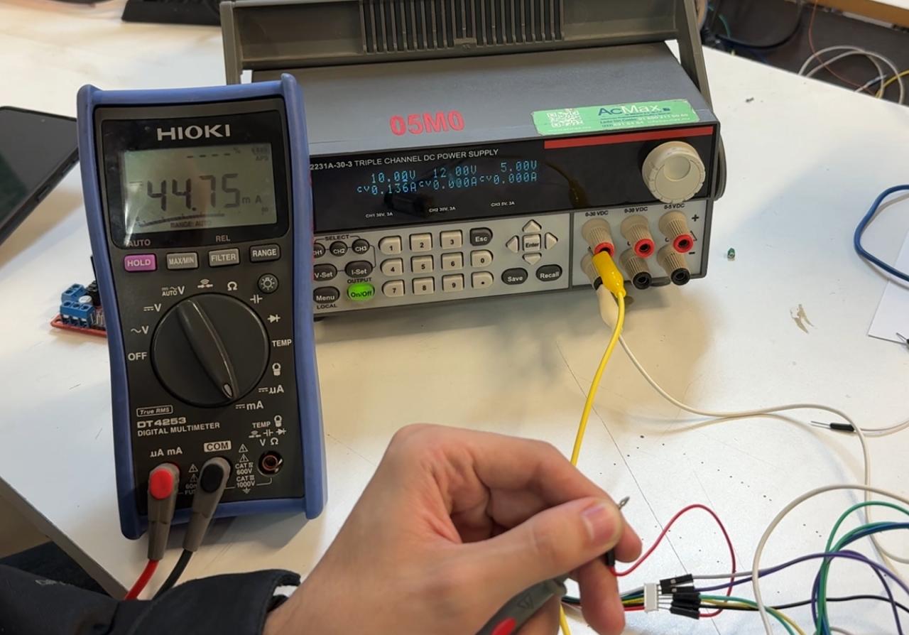
I used a multimeter to measure the motor´s power consumption by connecting the multimeter´s probes in series with the circuit and reading the current passing by.

When the motor is moving, the current is 0.044A. This means that the motor consumes 0.22 Watts.
Summary
This week, I successfully implemented a DC motor control system with encoder feedback using an ESP32 and L298N motor driver. I learned how to interpret encoder signals to determine motor direction and position, and created a system that can precisely control motor movement in both directions. The project brings me closer to completing my final project requirements.
