14. Interface and Application Programming
Summary
This week we wrote an application that interfaces a user with an input &/or output device of our own making. For our group assignment, we compared as many tool options as possible.
1. Introduction to Interfaces and Applications
In the context of digital systems, a User Interface (UI) is a visual or interactive medium through which a person interacts with a machine or software. Interfaces are essential to bridge the gap between a user's intent and the device's behavior, making systems accessible, efficient, and intuitive to control.
UIs are present everywhere — from smartphone screens and web pages to embedded device panels and physical buttons on appliances. They serve the primary function of capturing user input (e.g., clicks, commands, gestures) and providing feedback from the system (e.g., text, light, sound, or motion).
In FabAcademy, interfaces are particularly useful when working with microcontrollers or digital systems that require user input to trigger functions, control actuators, or monitor data.
1.1. Types of Interfaces
- Graphical User Interfaces (GUIs) - Visual elements like buttons, sliders, and fields that respond to clicks and touches. Examples include desktop applications and mobile apps.
- Command-Line Interfaces (CLIs) - Text-based systems that take keyboard input and return responses, like terminal or shell environments.
- Physical Interfaces - Buttons, knobs, and touch surfaces connected to electronics that allow tangible interaction.
- Web Interfaces - Browser-based GUIs built with HTML, CSS, and JavaScript that can run locally or remotely.
1.2. Interface Elements and Design Components
A well-designed interface includes both functional and aesthetic elements. These can include:
- Input Controls: Buttons, sliders, dropdowns, text fields.
- Output Displays: Text logs, status messages, graphs.
- Feedback Systems: Real-time response indicators such as logs or lights.
- Layout and Aesthetics: Color schemes, fonts, spacing, and animations that enhance usability.
1.3. What Are Applications?
Applications, or "apps," are software programs designed to perform specific tasks for users. In the context of interface programming, applications serve as the functional layer that receives input from the UI, processes it, and sends appropriate commands or feedback to connected systems.
An application might run on a desktop, mobile device, or microcontroller, and can vary in complexity from a simple command interpreter to an elaborate graphical control system. For projects involving microcontrollers (like those in FabAcademy), applications often serve as control bridges — interpreting user commands and relaying them through serial communication, Bluetooth, or network protocols to hardware.
A well-designed application ensures accurate communication with hardware components, allows debugging and testing through logs or visual feedback, and enhances the overall usability of a system.
1.4. Applications in Embedded Systems
In embedded systems and digital fabrication, applications play a critical role by providing human-readable interfaces for otherwise complex and invisible processes. Whether controlling motors, lighting LEDs, or collecting sensor data, applications help abstract low-level machine interactions into intuitive tools.
For instance, for this week's assignment, I developed a desktop application using Python and PyQt5 to interface with a XIAO RP2040 microcontroller. This application allowed me to:
- Connect to the microcontroller via USB serial.
- Send structured commands to control LEDs, servos, and stepper motors.
- Receive acknowledgments and feedback from the hardware.
- Log communication for troubleshooting and validation.
By building this interface application, I was able to focus more on my system's behavior, rather than the complexities of embedded protocol handling. It also provided a solid platform for possible future features such as live video integration, real-time feedback, and interactive visualization.
2. Tools and Technologies Used
For this assignment, I created a PC-based graphical interface to interact with my custom-made PCB featuring the Seeed XIAO RP2040 microcontroller. The application allows real-time control of various actuators including an onboard LED, two servos, and a NEMA17 stepper motor. Below are the tools and frameworks that made this possible:
2.1 PyQt5
PyQt5 is a set of Python bindings for the Qt application framework and was the primary toolkit used to design the graphical user interface. It enables rapid development of GUI applications with buttons, labels, dropdown menus, and more, all while maintaining full control over Python's logic.
2.2 Python 3
The main logic of the application was written in Python, a versatile language well-suited for serial communication, GUI integration, and hardware interfacing. Python libraries like pyserial were used to handle USB serial connections between the PC and the XIAO RP2040.
2.3 PySerial
PySerial is a Python library used to establish and manage serial communications. It enabled the application to open a USB COM port, send textual commands to the microcontroller, and listen for responses — creating a bi-directional communication channel essential for command acknowledgement and real-time control.
2.4 Custom Hardware (XIAO RP2040 PCB)
The application was designed specifically for a custom PCB based on the Seeed XIAO RP2040. This board was programmed to interpret commands such as LED_ON, MOVE_FORWARD, SERVO1_90, and respond with ACK for successful execution. The serial interface on the XIAO RP2040 serves as the primary communication line with the desktop app.
2.5 UI Design Considerations
While PyQt5 may not offer the same degree of aesthetic flexibility as HTML/CSS interfaces, the application was structured to provide a clear and intuitive user experience. Controls were laid out in logical groupings (e.g., LED toggle, motor direction, servo angles), and real-time status feedback was incorporated to improve usability and debuggability.
3. Programming
3.1 Application Code
The application was developed in Python, using the PyQt5 library for the graphical user interface (GUI) and pyserial for communication over the serial port. The GUI allows the user to control hardware connected to a XIAO RP2040 board, including an LED, two servo motors, and a NEMA17 stepper motor.
import sys
import serial
import serial.tools.list_ports
from PyQt5.QtWidgets import (QApplication, QWidget, QPushButton, QVBoxLayout, QHBoxLayout,
                             QLabel, QLineEdit, QTextEdit, QComboBox)
from PyQt5.QtCore import (QTimer)

class XiaoControlApp(QWidget):
    def __init__(self):
        super().__init__()
        self.ser = None
        self.initUI()

    def initUI(self):
        self.setWindowTitle("XIAO RP2040 Control Panel")
        self.setStyleSheet("background-color: #0a0a0a; color: #f0f0f0; font-family: Segoe UI;")

        layout = QVBoxLayout()

        # COM Port selection
        com_layout = QHBoxLayout()
        self.com_box = QComboBox()
        ports = serial.tools.list_ports.comports()
        for p in ports:
            self.com_box.addItem(p.device)
        com_layout.addWidget(QLabel("Port:"))
        com_layout.addWidget(self.com_box)

        self.baud_input = QLineEdit("9600")
        self.baud_input.setFixedWidth(80)
        com_layout.addWidget(QLabel("Baud:"))
        com_layout.addWidget(self.baud_input)

        self.connect_btn = QPushButton("Connect")
        self.connect_btn.setStyleSheet("background-color: #ff003c; color: white;")
        self.connect_btn.clicked.connect(self.connect_serial)
        com_layout.addWidget(self.connect_btn)

        layout.addLayout(com_layout)

        # LED Controls
        led_layout = QHBoxLayout()
        self.led_on_btn = QPushButton("LED ON")
        self.led_on_btn.clicked.connect(lambda: self.send_command("LED_ON"))
        self.led_off_btn = QPushButton("LED OFF")
        self.led_off_btn.clicked.connect(lambda: self.send_command("LED_OFF"))
        led_layout.addWidget(self.led_on_btn)
        led_layout.addWidget(self.led_off_btn)
        layout.addLayout(led_layout)

        # Servo Controls
        self.servo1_input = QLineEdit()
        self.servo1_btn = QPushButton("Set Servo1")
        self.servo1_btn.clicked.connect(lambda: self.send_command(f"SERVO1:{self.servo1_input.text()}"))
        layout.addWidget(QLabel("Servo1 Angle:"))
        layout.addWidget(self.servo1_input)
        layout.addWidget(self.servo1_btn)

        self.servo2_input = QLineEdit()
        self.servo2_btn = QPushButton("Set Servo2")
        self.servo2_btn.clicked.connect(lambda: self.send_command(f"SERVO2:{self.servo2_input.text()}"))
        layout.addWidget(QLabel("Servo2 Angle:"))
        layout.addWidget(self.servo2_input)
        layout.addWidget(self.servo2_btn)

        # Stepper Controls
        self.steps_input = QLineEdit()
        self.dir_input = QLineEdit()
        self.stepper_btn = QPushButton("Move Stepper")
        self.stepper_btn.clicked.connect(lambda: self.send_command(f"STEPPER:{self.steps_input.text()}:{self.dir_input.text()}"))
        layout.addWidget(QLabel("Steps:"))
        layout.addWidget(self.steps_input)
        layout.addWidget(QLabel("Direction (0 or 1):"))
        layout.addWidget(self.dir_input)
        layout.addWidget(self.stepper_btn)

        # Log Output
        self.log_box = QTextEdit()
        self.log_box.setReadOnly(True)
        self.log_box.setStyleSheet("background-color: #1a1a1a; color: white;")
        layout.addWidget(QLabel("Log Output:"))
        layout.addWidget(self.log_box)

        self.setLayout(layout)
        self.resize(400, 600)

        self.timer = QTimer()
        self.timer.timeout.connect(self.read_serial)
        self.timer.start(100)  # every 100 ms


    def connect_serial(self):
        port = self.com_box.currentText()
        baud = int(self.baud_input.text())
        try:
            self.ser = serial.Serial(port, baud, timeout=1)
            self.log(f"Connected to {port} at {baud} baud.")
        except Exception as e:
            self.log(f"Error connecting: {e}")

    def send_command(self, cmd):
        if self.ser and self.ser.is_open:
            try:
                self.ser.write((cmd + '\n').encode())
                self.log(f"Sent: {cmd}")
            except Exception as e:
                self.log(f"Error sending command: {e}")
        else:
            self.log("Serial not connected.")

    def read_serial(self):
        if self.ser and self.ser.in_waiting:
            try:
                data = self.ser.readline().decode().strip()
                if data:
                    self.log(f"< {data}")
            except Exception as e:
                self.log(f"[Error reading]: {e}")


    def log(self, msg):
        self.log_box.append(f"> {msg}")

if __name__ == "__main__":
    app = QApplication(sys.argv)
    window = XiaoControlApp()
    window.show()
    sys.exit(app.exec_())
1. Libraries and Initialization
import sys
import serial
import serial.tools.list_ports
from PyQt5.QtWidgets import (QApplication, QWidget, QPushButton, QVBoxLayout, QHBoxLayout,
                             QLabel, QLineEdit, QTextEdit, QComboBox)
from PyQt5.QtCore import QTimer
These import statements bring in necessary modules. sys is used for application control, serial and serial.tools.list_ports are part of pyserial for managing the serial communication, and PyQt5 modules are used to construct and manage the GUI.
2. Main Class and Constructor
class XiaoControlApp(QWidget):
    def __init__(self):
        super().__init__()
        self.ser = None
        self.initUI()
This defines the main GUI class. It inherits from QWidget, a base class for all user interface objects in PyQt. self.ser is used to store the serial connection. The initUI() method sets up the layout and widgets.
3. User Interface Setup
def initUI(self):
    self.setWindowTitle("XIAO RP2040 Control Panel")
    self.setStyleSheet("background-color: #0a0a0a; color: #f0f0f0; font-family: Segoe UI;")

    layout = QVBoxLayout()
This sets the window title and style. The layout is organized vertically using QVBoxLayout for stacking elements.
4. Serial Port Selector
    com_layout = QHBoxLayout()
    self.com_box = QComboBox()
    ports = serial.tools.list_ports.comports()
    for p in ports:
        self.com_box.addItem(p.device)
    com_layout.addWidget(QLabel("Port:"))
    com_layout.addWidget(self.com_box)
This section detects available serial ports and lets the user select one using a dropdown menu. It's part of a horizontal layout to align widgets side by side.
    self.baud_input = QLineEdit("9600")
    self.baud_input.setFixedWidth(80)
    com_layout.addWidget(QLabel("Baud:"))
    com_layout.addWidget(self.baud_input)
Adds an input for the user to specify the baud rate (communication speed), defaulting to 9600.
    self.connect_btn = QPushButton("Connect")
    self.connect_btn.setStyleSheet("background-color: #ff003c; color: white;")
    self.connect_btn.clicked.connect(self.connect_serial)
    com_layout.addWidget(self.connect_btn)
    layout.addLayout(com_layout)
The "Connect" button initiates the serial connection when clicked, calling the connect_serial function.
5. LED Control Buttons
    led_layout = QHBoxLayout()
    self.led_on_btn = QPushButton("LED ON")
    self.led_on_btn.clicked.connect(lambda: self.send_command("LED_ON"))
    self.led_off_btn = QPushButton("LED OFF")
    self.led_off_btn.clicked.connect(lambda: self.send_command("LED_OFF"))
    led_layout.addWidget(self.led_on_btn)
    led_layout.addWidget(self.led_off_btn)
    layout.addLayout(led_layout)
These two buttons send commands to turn the LED on and off. The use of lambda allows inline command sending.
6. Servo Motor Controls
    self.servo1_input = QLineEdit()
    self.servo1_btn = QPushButton("Set Servo1")
    self.servo1_btn.clicked.connect(lambda: self.send_command(f"SERVO1:{self.servo1_input.text()}"))
    layout.addWidget(QLabel("Servo1 Angle:"))
    layout.addWidget(self.servo1_input)
    layout.addWidget(self.servo1_btn)
Input and button for Servo 1 angle, which sends a command like SERVO1:90 to rotate it to 90 degrees.
    self.servo2_input = QLineEdit()
    self.servo2_btn = QPushButton("Set Servo2")
    self.servo2_btn.clicked.connect(lambda: self.send_command(f"SERVO2:{self.servo2_input.text()}"))
    layout.addWidget(QLabel("Servo2 Angle:"))
    layout.addWidget(self.servo2_input)
    layout.addWidget(self.servo2_btn)
Same functionality for Servo 2.
7. Stepper Motor Controls
    self.steps_input = QLineEdit()
    self.dir_input = QLineEdit()
    self.stepper_btn = QPushButton("Move Stepper")
    self.stepper_btn.clicked.connect(lambda: self.send_command(f"STEPPER:{self.steps_input.text()}:{self.dir_input.text()}"))
    layout.addWidget(QLabel("Steps:"))
    layout.addWidget(self.steps_input)
    layout.addWidget(QLabel("Direction (0 or 1):"))
    layout.addWidget(self.dir_input)
    layout.addWidget(self.stepper_btn)
Allows the user to send step and direction data to move the stepper motor accordingly. Commands look like STEPPER:200:1.
8. Serial Monitor Log
    self.log_box = QTextEdit()
    self.log_box.setReadOnly(True)
    self.log_box.setStyleSheet("background-color: #1a1a1a; color: white;")
    layout.addWidget(QLabel("Log Output:"))
    layout.addWidget(self.log_box)
A read-only text area displays logs and feedback from the board, including acknowledgments or errors.
9. Timer for Reading Serial Data
    self.timer = QTimer()
    self.timer.timeout.connect(self.read_serial)
    self.timer.start(100)
A timer checks the serial port every 100 ms for any incoming messages from the microcontroller.
10. Serial Connection Function
def connect_serial(self):
    port = self.com_box.currentText()
    baud = int(self.baud_input.text())
    try:
        self.ser = serial.Serial(port, baud, timeout=1)
        self.log(f"Connected to {port} at {baud} baud.")
    except Exception as e:
        self.log(f"Error connecting: {e}")
Opens the selected port with the specified baud rate. Any errors are logged for debugging.
11. Command Function
def send_command(self, cmd):
    if self.ser and self.ser.is_open:
        try:
            self.ser.write((cmd + '\n').encode())
            self.log(f"Sent: {cmd}")
        except Exception as e:
            self.log(f"Error sending command: {e}")
    else:
        self.log("Serial not connected.")
Formats and sends commands over the serial
12. Reading Responses
def read_serial(self):
    if self.ser and self.ser.in_waiting:
        try:
            data = self.ser.readline().decode().strip()
            if data:
                self.log(f"< {data}")
        except Exception as e:
            self.log(f"[Error reading]: {e}")
Reads data from the serial buffer, decodes it, and displays it in the log. This supports two-way communication.
13. Logging Function
def log(self, msg):
    self.log_box.append(f"> {msg}")
Simple utility to format and append messages to the log window.
14. Main Function
if __name__ == "__main__":
    app = QApplication(sys.argv)
    window = XiaoControlApp()
    window.show()
    sys.exit(app.exec_())
This block initializes and displays the GUI. It also ensures a proper exit when the window is closed.
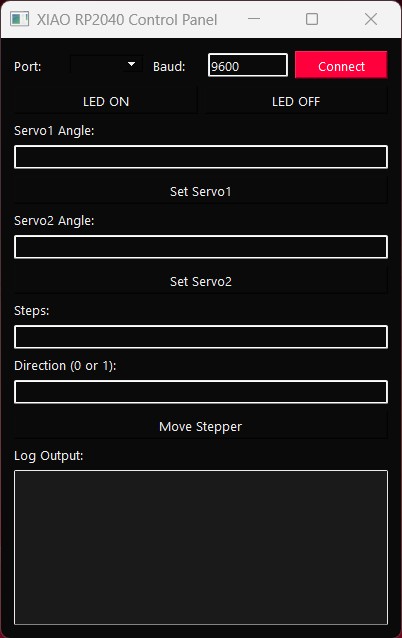
Once complete, this is how the UI came out:
3.2 Microcontroller Code
The following Arduino sketch was uploaded to the XIAO RP2040 board. It interprets commands received via the serial port to control an LED, two servo motors, and a stepper motor. It uses the Servo.h library and standard Arduino functions for GPIO manipulation.
1. Library and Pin Definitions
#include <Servo.h>

#define LED_PIN D8
#define SERVO1_PIN D9
#define SERVO2_PIN D10
#define DIR_PIN D3
#define STEP_PIN D4
The Servo.h library enables easy control of servo motors. Pin constants are defined for easier configuration and readability.
2. Global Servo Objects
Servo servo1;
Servo servo2;
These two objects represent the servo motors and will be used to set their angles.
3. Setup Function
void setup() {
  Serial.begin(9600);

  pinMode(LED_PIN, OUTPUT);
  pinMode(DIR_PIN, OUTPUT);
  pinMode(STEP_PIN, OUTPUT);

  servo1.attach(SERVO1_PIN);
  servo2.attach(SERVO2_PIN);

  servo1.write(90);  // center
  servo2.write(90);  // center

  Serial.println("XIAO RP2040 ready.");
}
The setup() function initializes serial communication, sets pin modes for outputs, attaches servos to their pins, and centers them at 90°. A welcome message is printed to indicate the board is ready.
4. Main Loop
void loop() {
  if (Serial.available()) {
    String cmd = Serial.readStringUntil('\n');
    cmd.trim();
Inside the loop(), the board waits for a complete line (ending with newline) over the serial port, trims whitespace, and then processes the command.
5. LED Control
    if (cmd == "LED_ON") {
      digitalWrite(LED_PIN, HIGH);
      Serial.println("ACK:LED_ON");
    } else if (cmd == "LED_OFF") {
      digitalWrite(LED_PIN, LOW);
      Serial.println("ACK:LED_OFF");
Commands LED_ON and LED_OFF switch the LED on and off. A confirmation (ACK) is printed back for feedback in the GUI log.
6. Servo Control
    } else if (cmd.startsWith("SERVO1:")) {
      int angle = cmd.substring(7).toInt();
      servo1.write(constrain(angle, 0, 180));
      Serial.println("Servo1 moved to " + String(angle));

    } else if (cmd.startsWith("SERVO2:")) {
      int angle = cmd.substring(7).toInt();
      servo2.write(constrain(angle, 0, 180));
      Serial.println("Servo2 moved to " + String(angle));
Servo angle commands are formatted like SERVO1:90. The angle is parsed from the string, constrained to a valid range (0–180°), and passed to the servo object. Feedback is provided via serial.
7. Stepper Motor Control
    } else if (cmd.startsWith("STEPPER:")) {
      int firstColon = cmd.indexOf(':');
      int secondColon = cmd.indexOf(':', firstColon + 1);

      int steps = cmd.substring(firstColon + 1, secondColon).toInt();
      int direction = cmd.substring(secondColon + 1).toInt();

      digitalWrite(DIR_PIN, direction);
      for (int i = 0; i < steps; i++) {
        digitalWrite(STEP_PIN, HIGH);
        delayMicroseconds(800);
        digitalWrite(STEP_PIN, LOW);
        delayMicroseconds(800);
      }
      Serial.println("Stepper moved " + String(steps) + " steps in direction " + String(direction));
    }
  }
}
The command format STEPPER:200:1 contains the number of steps and direction. It splits the string at the colons, extracts the values, and then toggles the STEP_PIN that many times while setting the direction pin. The delay controls speed. A status message is returned to the GUI.
4. Setup
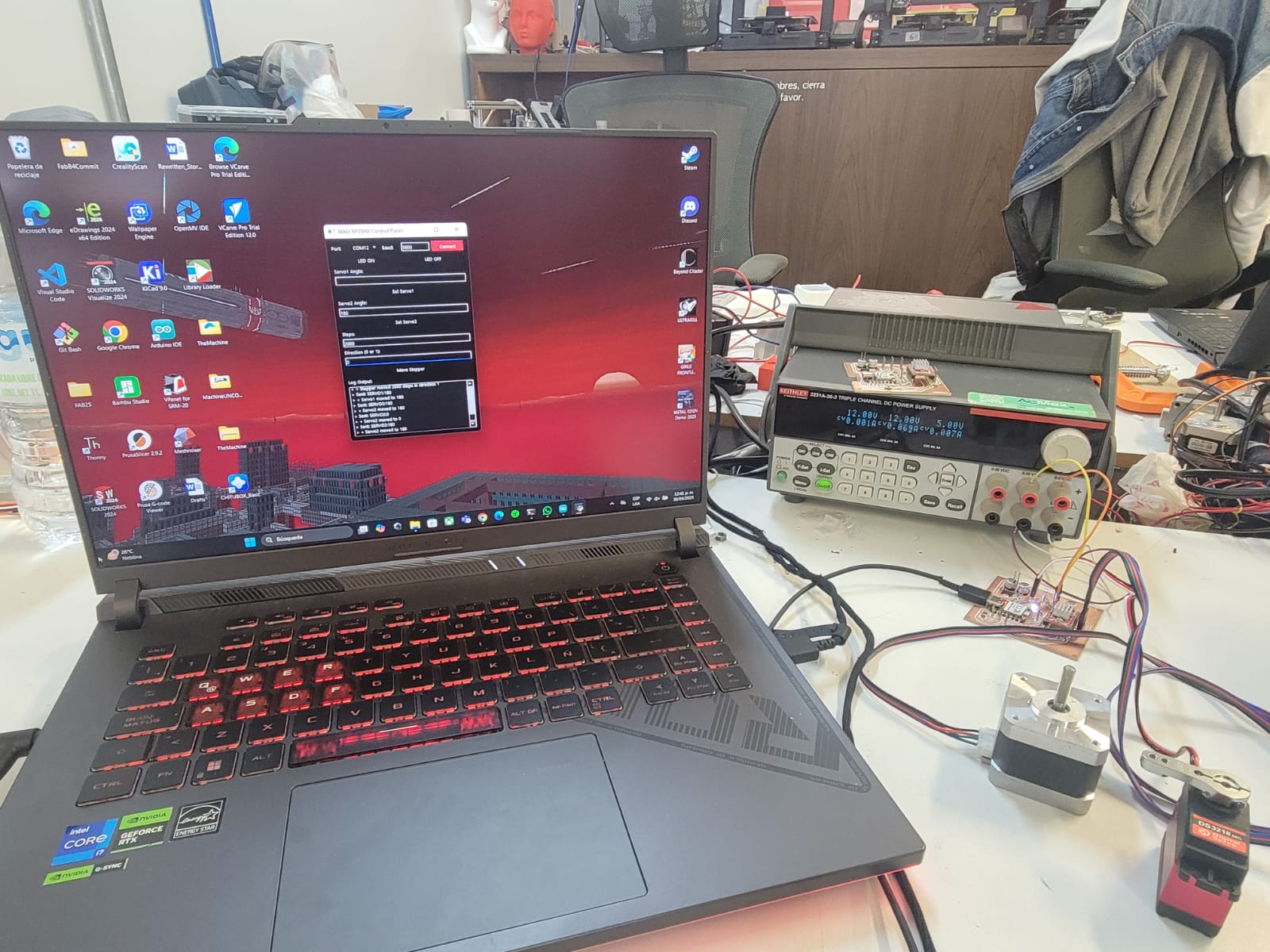
The physical setup for this project was straightforward yet essential for ensuring reliable communication and control. The DS3218 servo motors and the NEMA 17 stepper motor were connected to the designated pins on my V3 PCB, developed during week 11. Each component was powered using an external power supply connected to the board, with control signals routed to their respective digital I/O pins: D9 and D10 for the servos, and D3 and D4 for the stepper motor's direction and step control. Additionally, an onboard LED connected to pin D8 served as a simple output for testing serial command reception.
Once the hardware was correctly wired, the board was connected to the PC via a USB cable. This USB connection not only supplied power but also enabled the serial communication link between the desktop application and the microcontroller. With the proper configuration on both the software and firmware sides, this setup allowed for real-time, bidirectional control and feedback.
This is this week's hero shot:
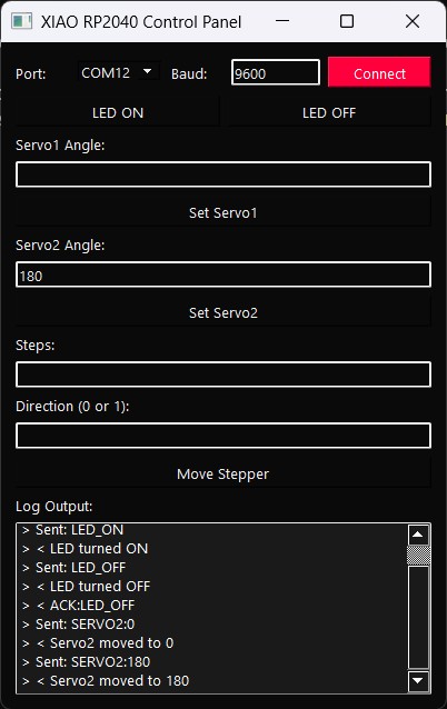
5. Testing and Results
Once intitialized, I selected the correct COM port and baud rate, and began sending commands, in responce, our UI's log correctly registered the inputs and responses, and the board followed said commands just as intended.
6. Comments and Recommendations
At the beginning of this assignment, I attempted to implement the interface using an HTML/JavaScript-based approach, specifically leveraging the Electron framework. While the initial idea was promising — given the flexibility and aesthetic potential of web technologies — several complications emerged during development.
A key issue was the difficulty of accessing the serial port from within the sandboxed environment of Electron. Despite multiple attempts and different bundling methods, the application consistently failed to load the preload scripts, and modules like serialport were either not recognized or lacked permissions to execute.
This experience highlighted that while web-based interfaces can be powerful, they also come with a significant overhead in terms of security configurations, module dependencies, and cross-platform compatibility — all of which can become bottlenecks if not expertly managed.
7. Learning Outcomes
7. Learning Outcomes
This assignment served as a valuable exercise in bridging the gap between physical hardware and software interfaces. By developing a desktop application capable of communicating with a XIAO RP2040-based board, I learned to manage both sides of the interaction, the application code and the embedded firmware. The project challenged me to build a user-friendly graphical interface using PyQt5, enabling the control of LEDs, servos, and a stepper motor. This process reinforced my understanding of GUI design principles, particularly the importance of organizing inputs, feedback mechanisms, and control logic in a way that eases usability.
While I initially attempted to create a web-based interface using Electron, I encountered several compatibility and communication issues related to accessing hardware resources through the browser. These difficulties highlighted the necessity of choosing tools that align well with the project's hardware requirements. Ultimately, shifting to a PyQt-based solution allowed me to achieve a more stable and effective result. This experience reminded me that understanding the limitations of tools is just as crucial as knowing their features.