13. Molding and Casting
Summary
This week we had to design a mold, produce it with a smooth surface finish that does not show the production process toolpath, and use it to cast parts. For our group assignment, we reviewed the safety data sheets for each of our molding and casting materials, then made and compared test casts with each of them, as well as comparing our mold making processes.
1. Introduction to Molding and Casting
Molding and casting are ancient but essential processes that continue to play a critical role in modern manufacturing. These techniques involve creating a mold — a negative impression of an object — and then pouring a material into the mold to reproduce the object's shape once it hardens. This allows for rapid replication of complex shapes with a high degree of accuracy.
Molding refers to the creation of the mold itself, which can be made from soft or hard materials depending on the application. Casting is the act of filling this mold with a liquid material that later solidifies, forming the final object. These processes are extremely versatile and are used across industries like automotive, aerospace, medical devices, jewelry, and prototyping.
Advantages of molding and casting include:
- High repeatability for mass production.
- Ability to produce complex geometries.
- Flexibility to use a wide range of materials (resins, plastics, metals, etc.).
- Cost-effective for medium to large production runs.
Disadvantages of molding and casting include:
- Initial mold production can be time-consuming and costly.
- Material limitations based on mold properties (temperature resistance, chemical compatibility).
- Potential for defects like bubbles, warping, or incomplete fills.
- Handling and environmental safety concerns, especially with resins and curing agents.
2. Mold Design
The first step in the molding and casting process was the design of the molds. My objective was to create a pawn chess piece using a hard material, which required me to design molds of molds, following the fundamental rule of moving from hard to soft materials, and vice-versa.
I designed two different sets of molds using SolidWorks:
- Two large half-molds of a pawn for 3D printing using an Elegoo Saturn 2 resin printer.
- Two smaller half-molds of the same pawn, adapted for milling out of a block of Ferris® Turquoise machinable wax.
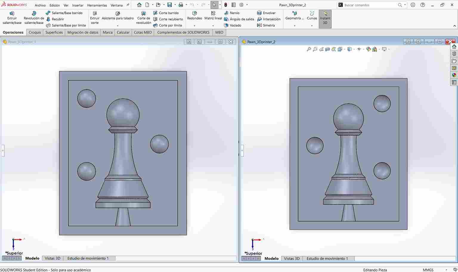
2.1 3D Printed Molds
For the printed molds, I designed two rectangular boxes that each contained the positive impression of half the pawn, integrating a cone-shaped pouring channel at the base for introducing casting material. The walls of the boxes were designed at 5 mm thickness, which proved strong enough to maintain structural integrity without excessive material usage. Upon reflection, a 3 mm wall thickness would likely have been sufficient.
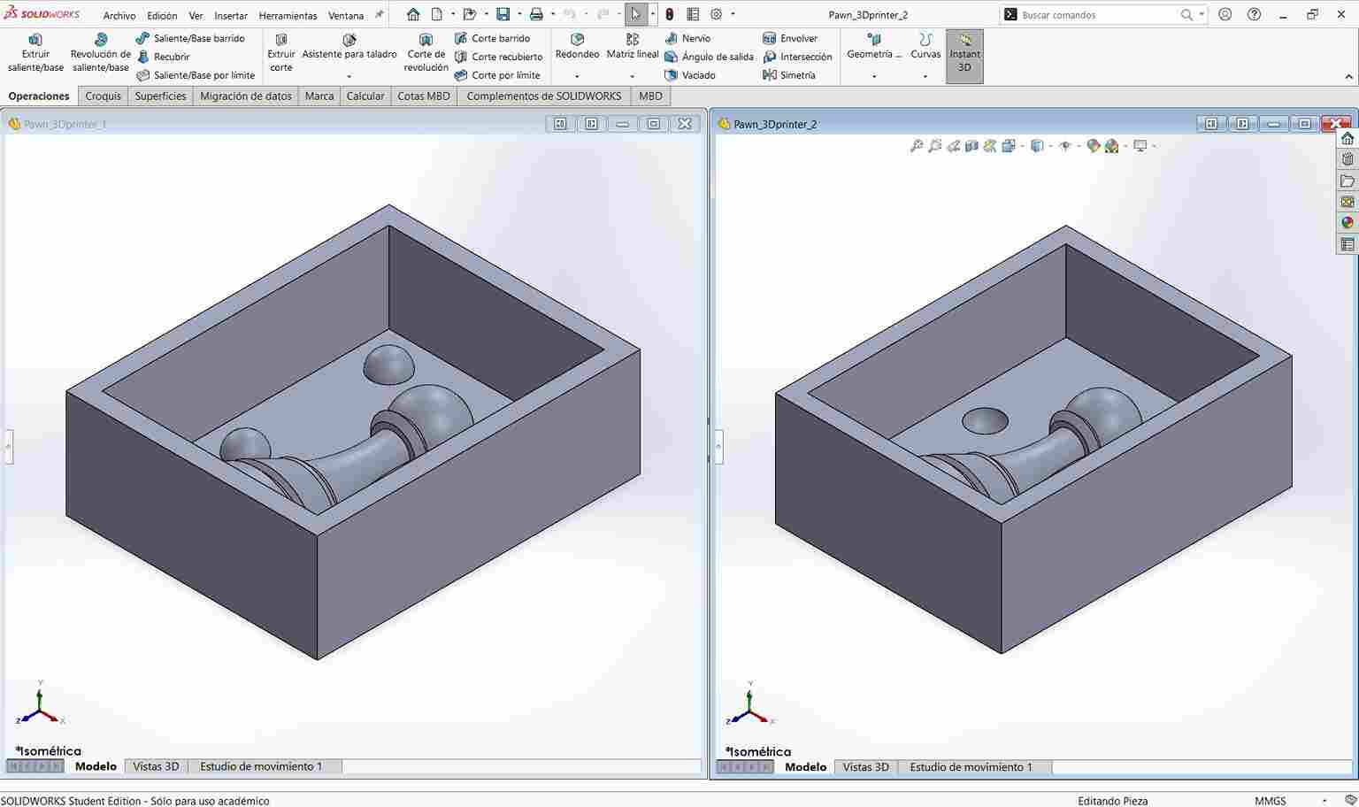
A critical design consideration was maintaining at least 10 mm of material thickness between the pawn and the mold walls (including the back side), to ensure robustness during casting.
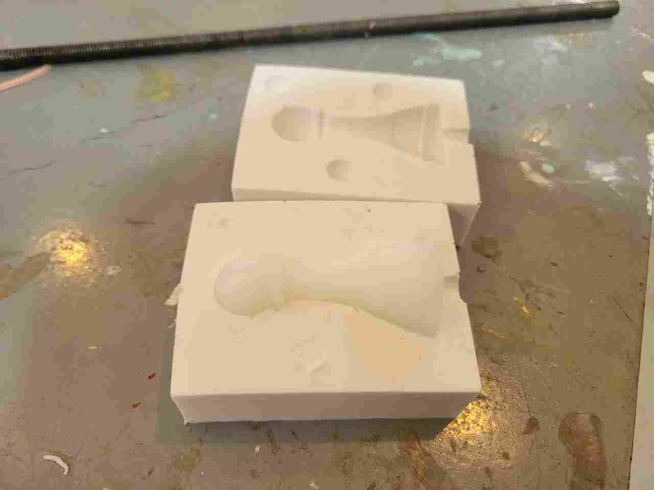
2.2 Wax Molds
For the wax molds, the design followed the same concept, but with additional constraints:
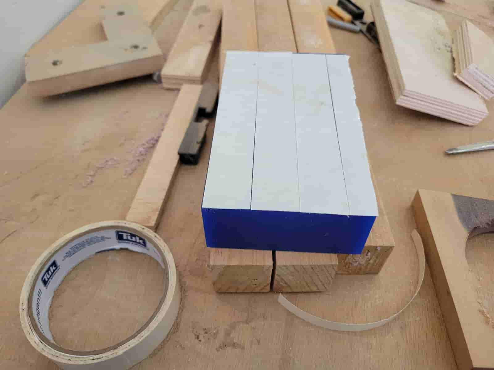
- The available wax block measured 147 mm x 88 mm x 35 mm.
- The milling tools had limited flute lengths and diameters, requiring careful geometric adaptations.
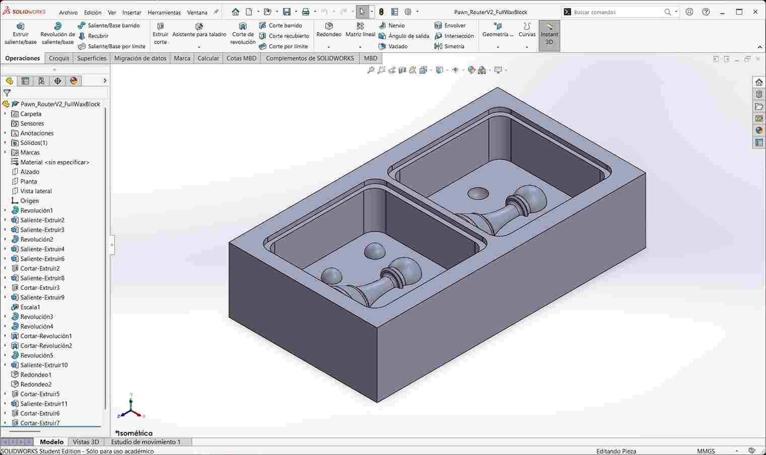
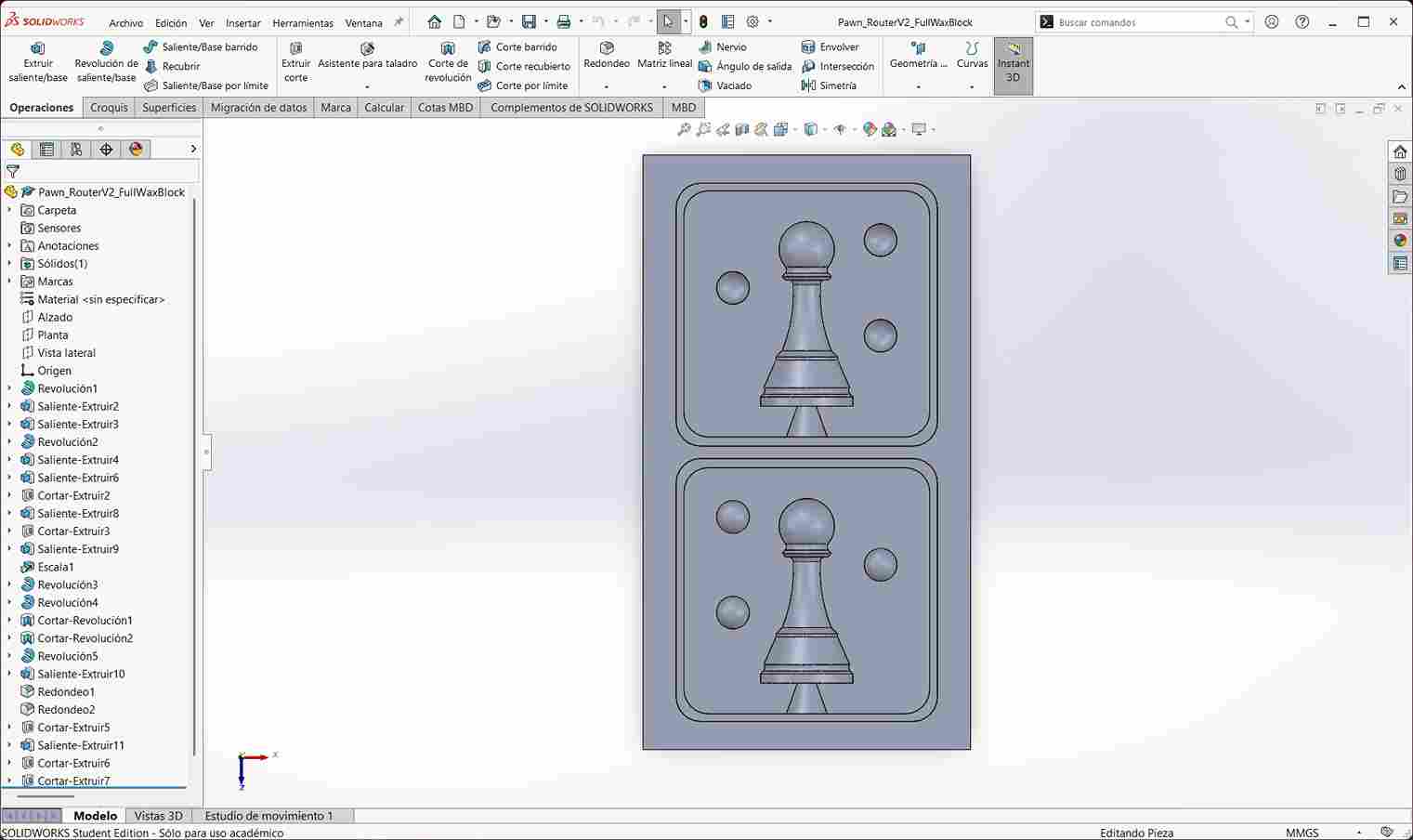 The pawn was scaled down by 25%, and sharp internal corners were avoided to accommodate the limitations of the milling tools.
A crucial limitation was the depth of the mold, restricted to 22.5 mm, slightly less than the 25 mm flute length of my shortest end mill. This precaution avoided collisions between the tool shank and the mold walls, preventing possible tool breakage.
DESIGN FLAW
One design flaw I encountered was the improper creation of the alignment spheres intended to guide the mold halves during assembly. Instead of mirroring the sphere placements correctly between halves, I accidentally duplicated the same configuration on both sides. As a result, the spheres could not fit into the intended cavities. To avoid additional material and machine-time consumption that would affect my peer's own assigments, I decided to cut off the spheres manually, instead of making new molds accepting the loss of automatic alignment features in the molds. This flaw has been corrected for the final design files and the images above to represent the ideal version of the molds, in case someone wishes to use them for future reference.
3. 3D Resin Mold Production
3.1 CHITUBOX Slicer
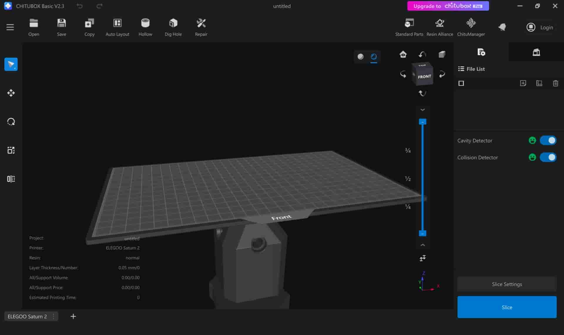
I began by installing CHITUBOX Basic software and selecting my printer, an Elegoo Saturn 2 resin 3D printer.
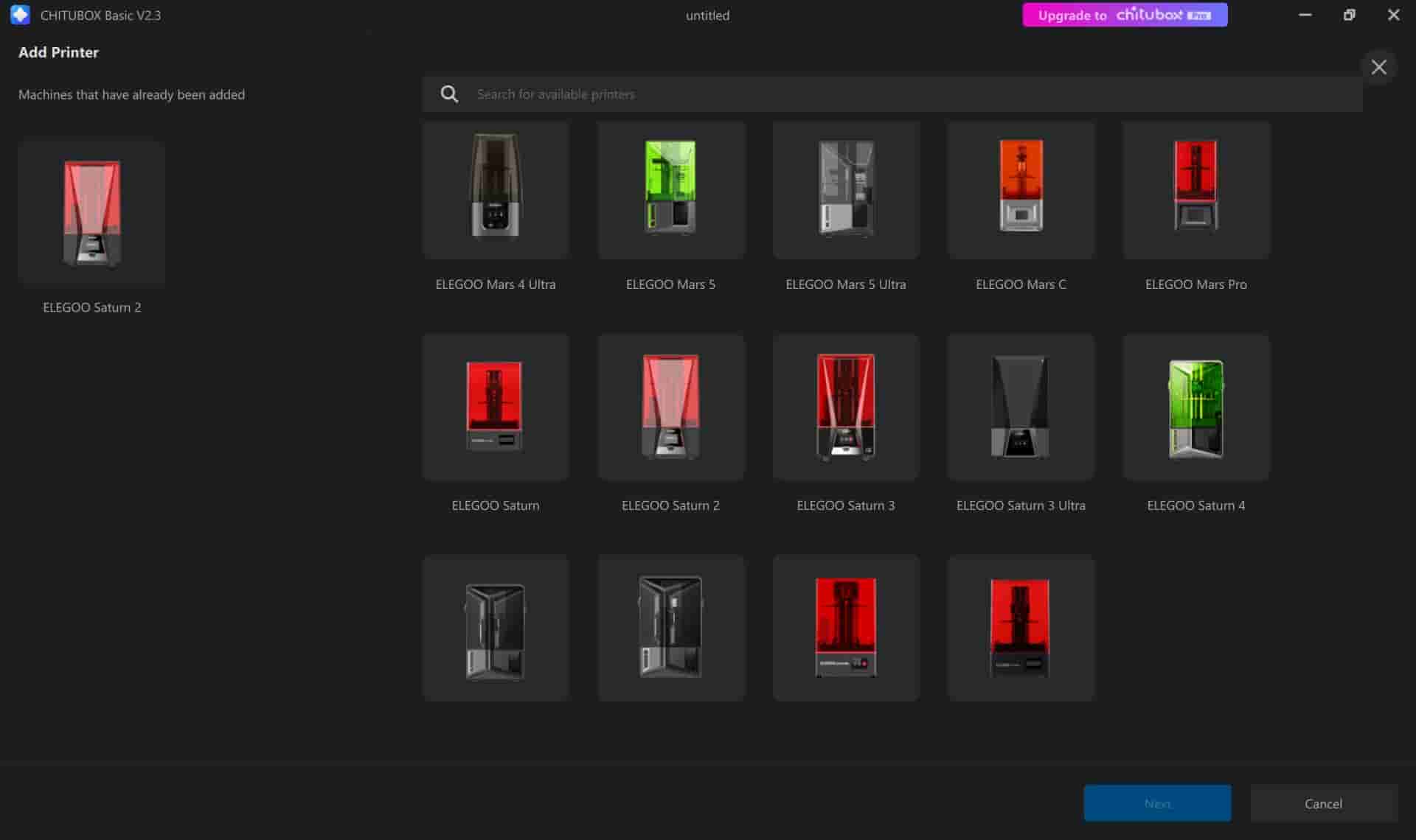
Upon first setup, the software prompted me to create a printing profile, which defines critical machine operations such as:
- Layer Exposure Time - How long UV light cures each layer of resin
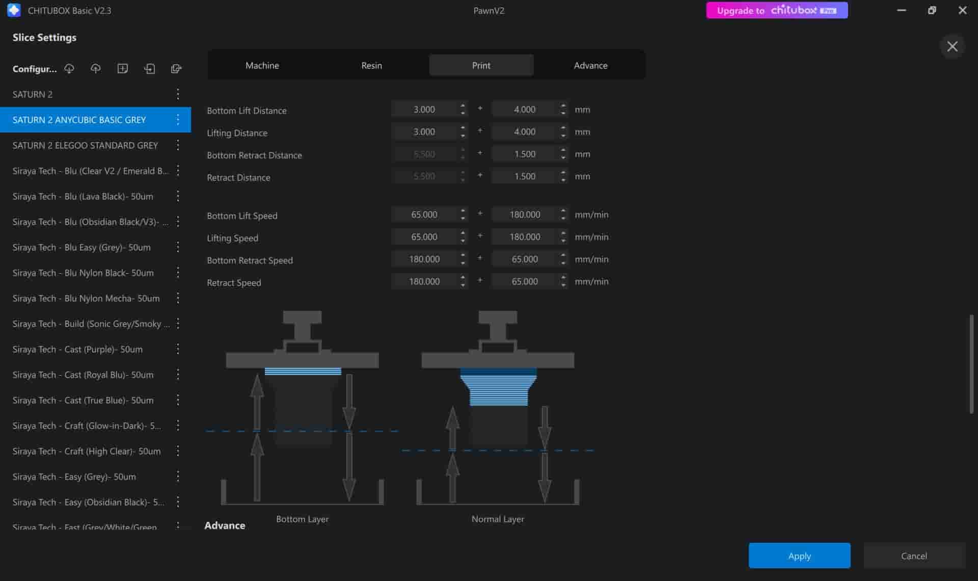
- Bottom Exposure Time - Special curing time for the first few layers for stronger adhesion
- Lift Speed and Retraction Distance - How fast and how far the platform moves between layers
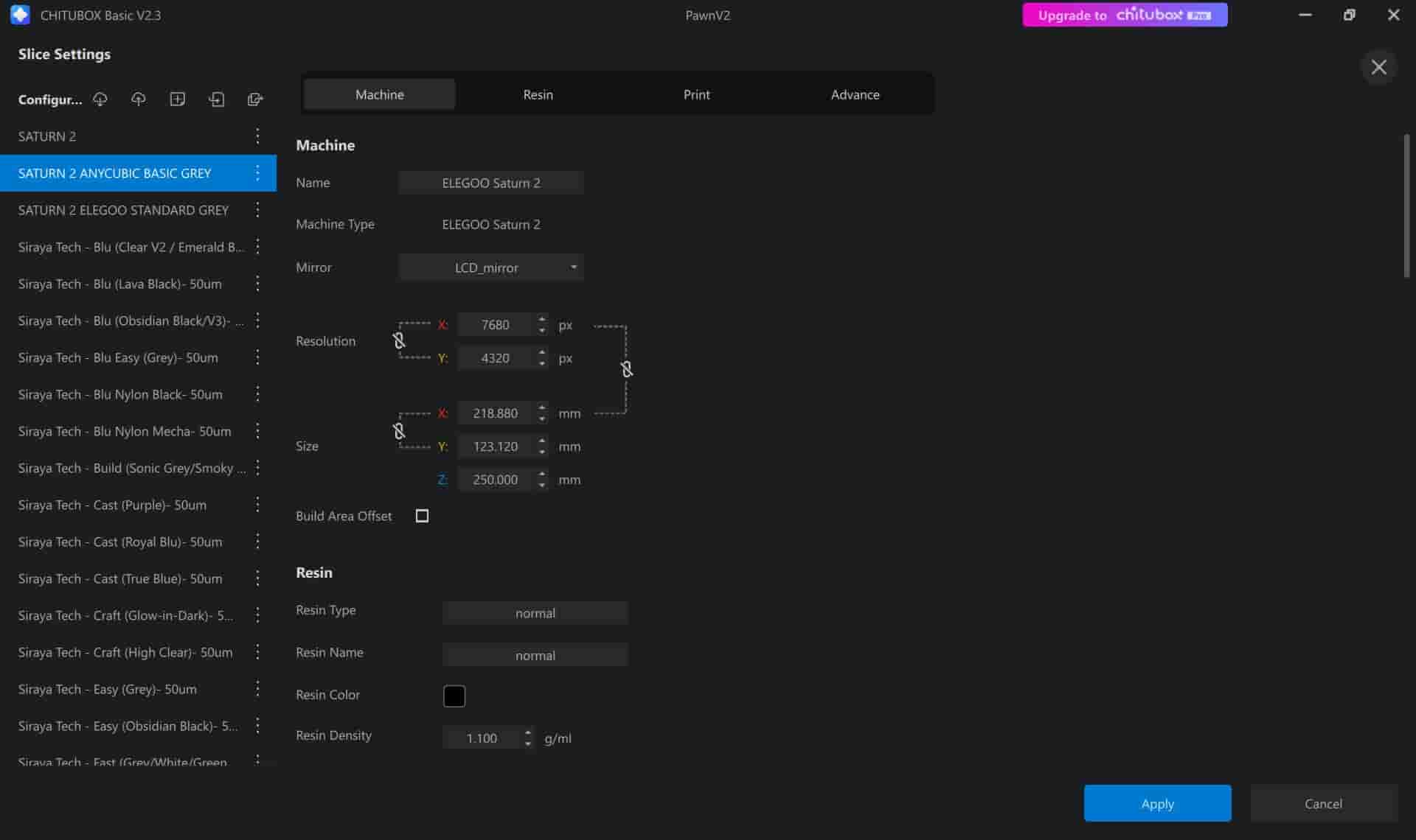
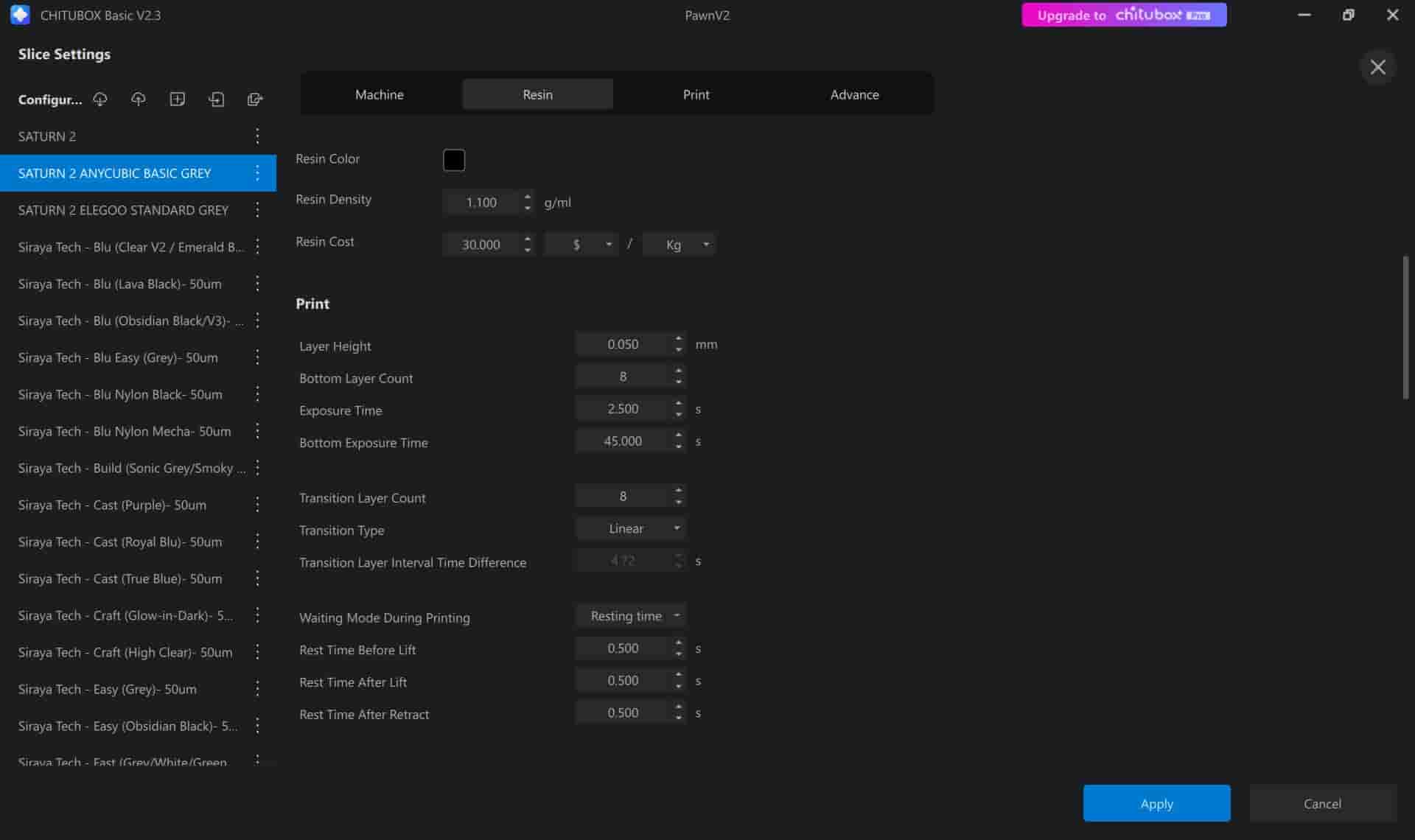
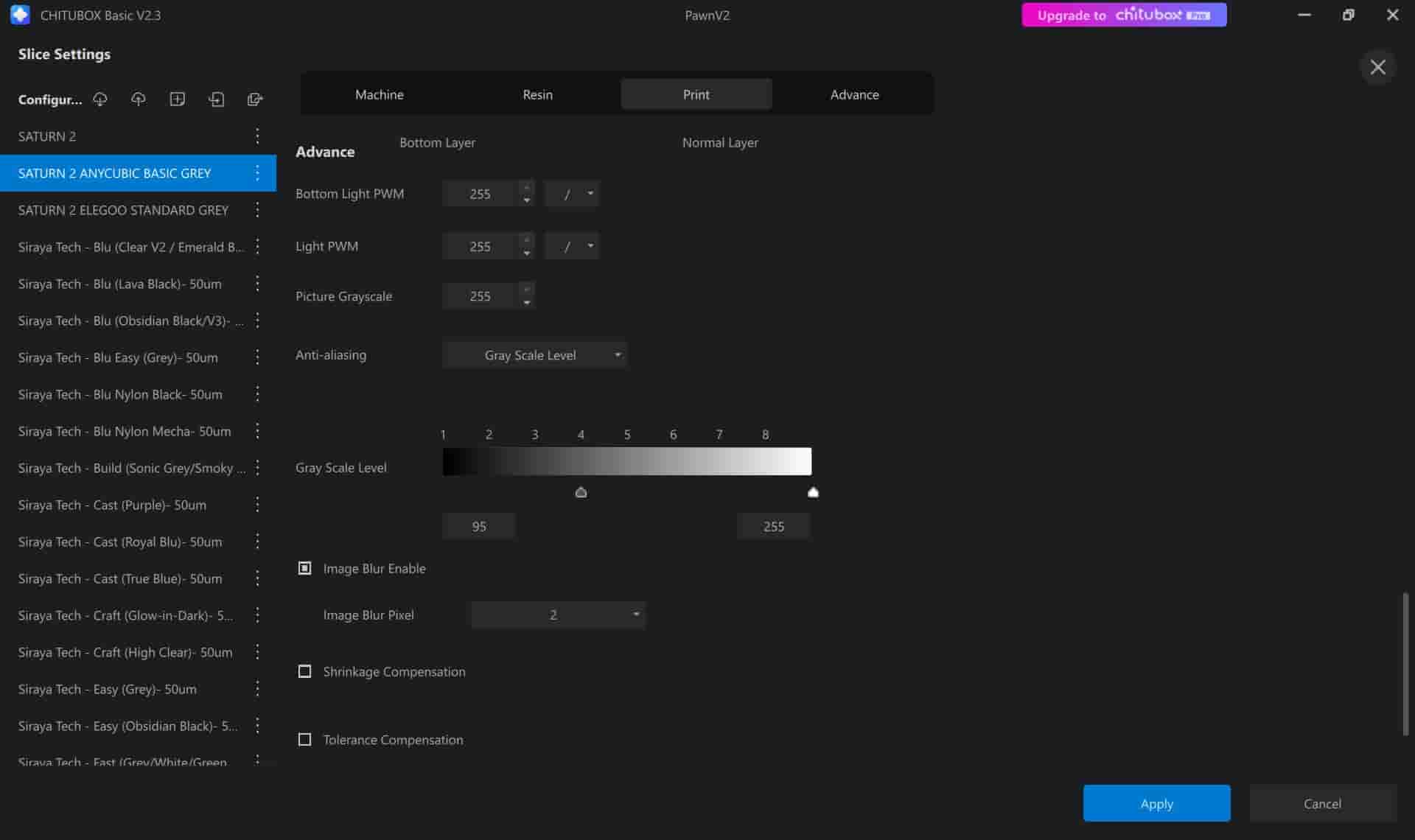 Each resin has unique characteristics, so every material requires specific parameters. Companies usually provide these recommended settings, but if they are not available, users often consult online forums and communities for guidance. It is crucial to configure the correct profile for the material and printer combination to ensure print quality and avoid failures.
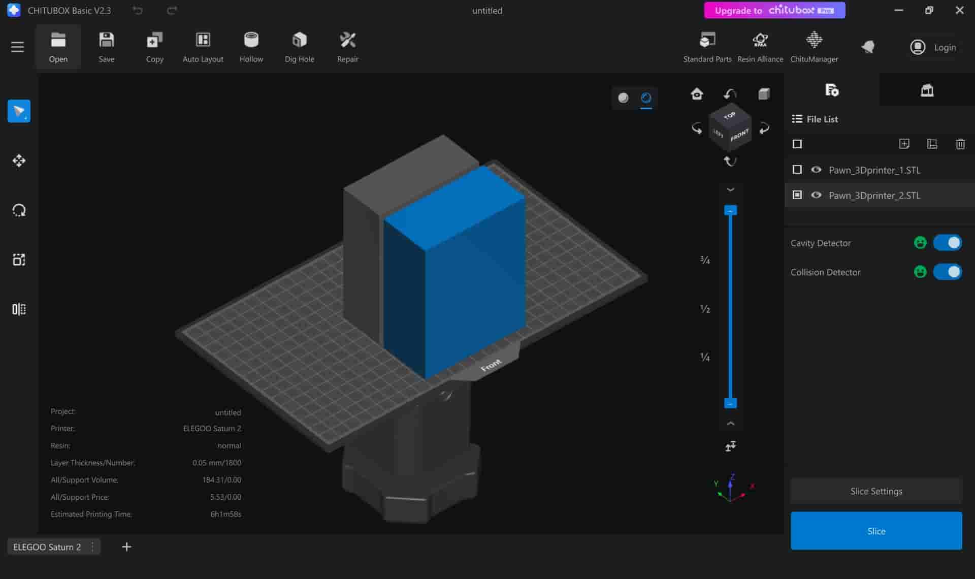
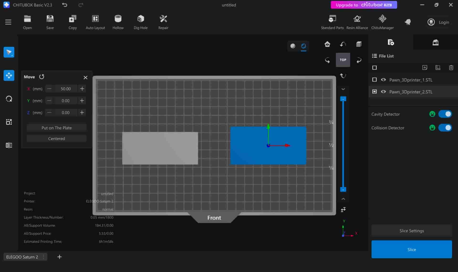
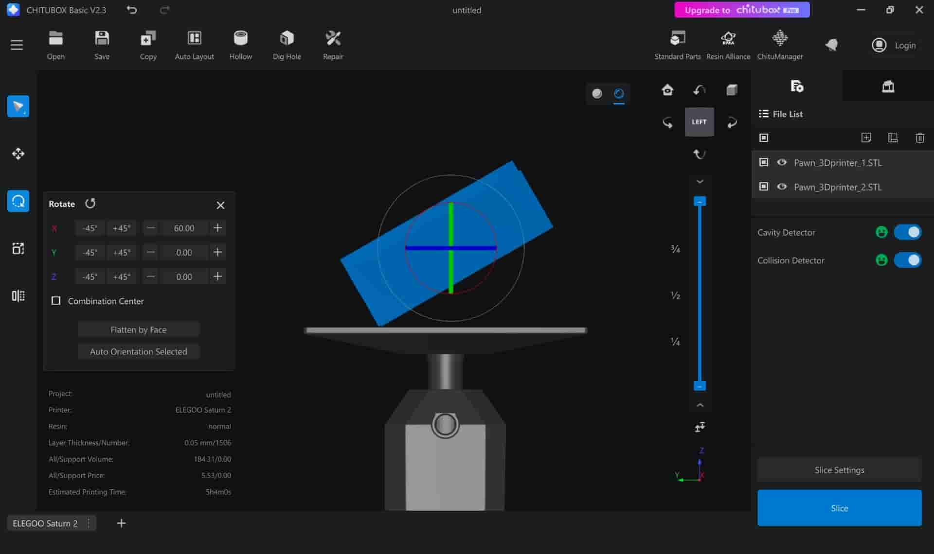
Once the profile was configured, I imported the STL file of my mold design. Proper placement on the build plate is critical. Ideally:
- Faces where fine detail is required should be positioned facing upwards, away from the bed.
- Models should be tilted slightly (~10-15°) to avoid creating large flat surfaces at once, which can lead to suction forces or layer failures.
If a model is thick (typically thicker than 5mm), it should be hollowed to reduce resin use. Drain holes are added to allow uncured resin to escape, preventing internal defects and reducing curing stresses.
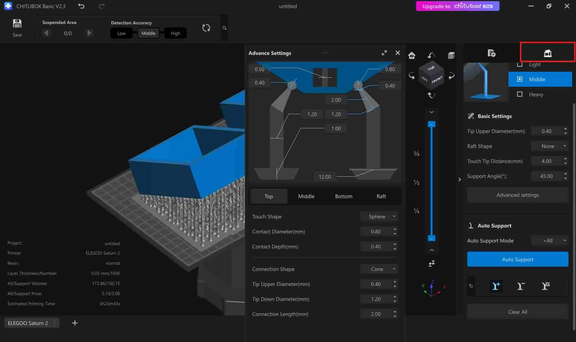
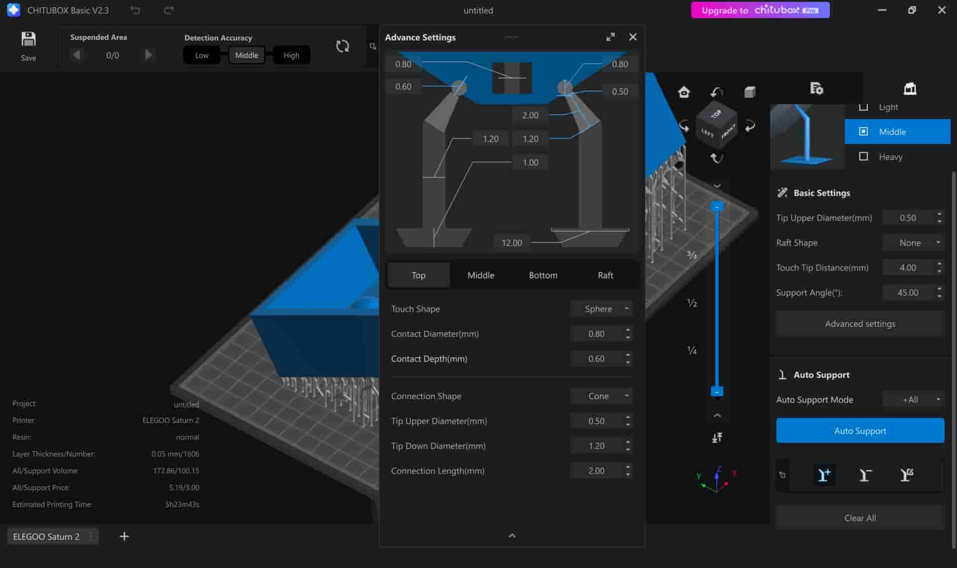
Before slicing, I added support structures to hold the model securely during the printing process. Support parameters such as contact point size, thickness, and density can be adjusted. It is worth noting that removing resin supports can leave very noticeable marks and usually requires sanding or post-processing.
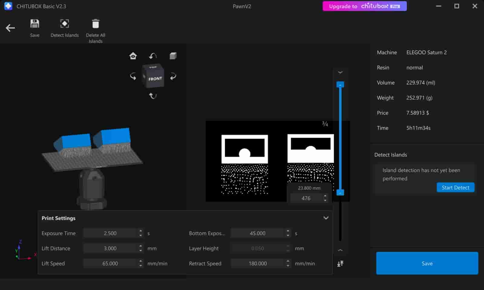
Finally, I sliced the model, generating a layer-by-layer preview of the print, and saved the result as a .ctb file onto a thumb drive.
3.2 Printing the Mold
My first physical interaction with the Elegoo Saturn 2 involved observing one of my classmates' prints, learning the workflow, and safety protocols. Resin 3D printing involves hazardous materials, so it is mandatory to work with gloves and preferably under good ventilation.
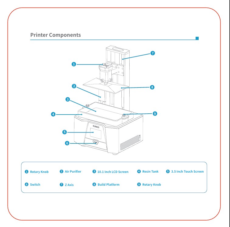
The basic procedure followed:
- Filling the resin vat with liquid photopolymer resin
- Ensuring the platform is correctly leveled
- Sealing the machine's cover to protect against UV light exposure
- Loading the sliced .ctb file from the thumb drive and starting the print
The Elegoo Saturn 2 then begins layer-by-layer curing using UV light, gradually building up the mold in high detail. Resin prints take longer than FDM prints but produce smoother and more detailed surfaces, making them ideal for mold masters.
3.3 First 3D Print: Failure
My first 3D printing attempt, using Elegoo rapid standard grey resin, and its official profile parameters, ended in a catastrophic failure. During the print, I observed that one of the parts failed at approximately 10% completion, and the second part failed around 40% completion. In both cases, the primary cause was the detachment of the base raft from the build plate, resulting in the first part not being fabricated at all, and the second sagging heavily beyond usability.
Unfortunately, since I left the printer running overnight, I did not detect the failure until the following day. This first print was made using Elegoo Rapid Standard Grey Resin with the official Elegoo profile parameters for the Saturn 2.
After consulting with my local instructor, the cause of the failure was determined to be a combination of slight printer miscalibration and insufficient raft exposure time and number of bottom layers. These factors likely contributed to weak adhesion between the print and the plate.
To recover, I first removed the failed print carefully, placing the damaged pieces on sheets of paper to allow excess resin to drain. Then, I started cleaning the machine:
- Wiped the build plate and the plate mount with paper towels to remove resin residue.
- Unscrewed the resin vat and poured the remaining resin back into its original bottle.
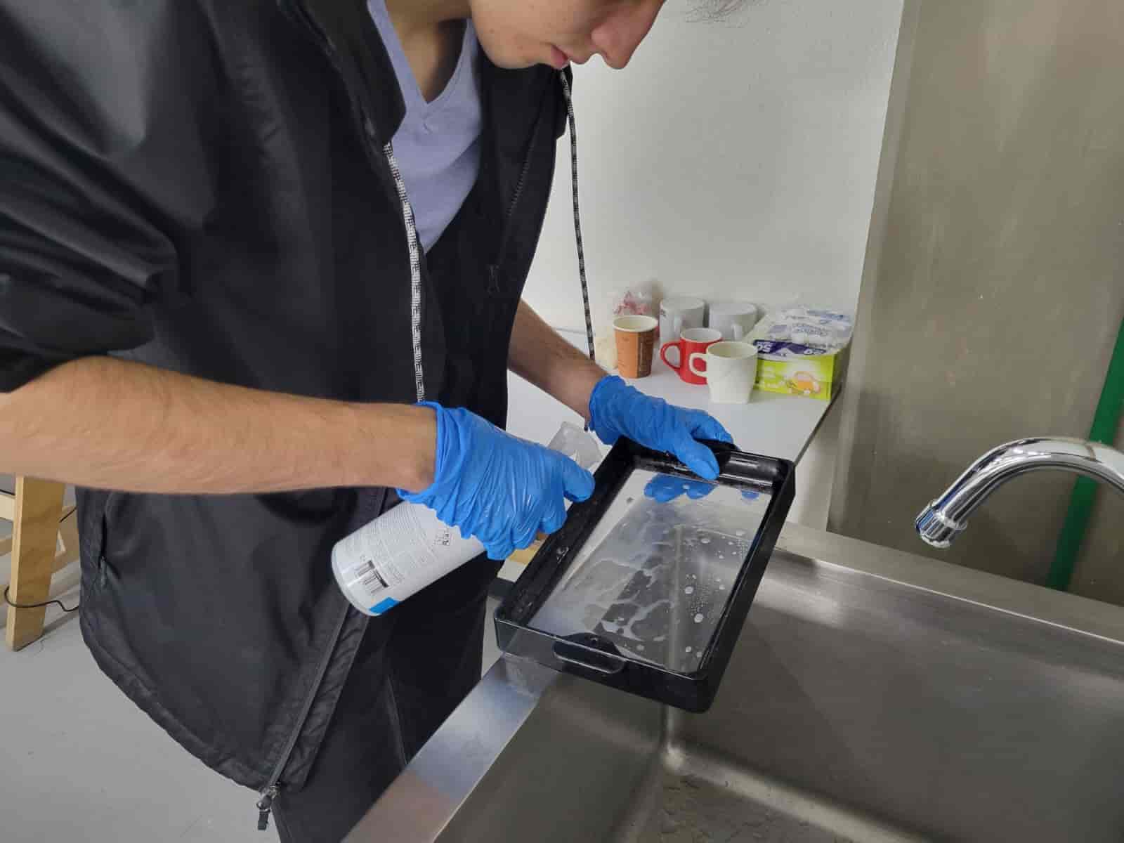
To clean the printer:
- I gently wiped the build plate and mount using paper towels soaked with isopropyl alcohol (IPA) until fully clean.
- For the resin vat, I moved to a sink area (for safety, not to dispose resin down the drain), and sprayed the FEP film with copious amounts of IPA, gently rubbing to avoid damaging the delicate surface.
- I absorbed the dissolved resin with disposable towels and discarded them in a contaminated solids waste bin.
Once the printer was fully clean and dry, I opened a new bottle of Anycubic Basic Grey Resin. Since this resin does not have official parameters for the Saturn 2, I researched various 3D printing forums and community guides to approximate proper settings, giving special attention to raft parameters and initial layer exposure.
After re-slicing the models with the updated profile, I began printing again. This time, I manually paused the print at 10% intervals to visually verify adhesion and printing quality.
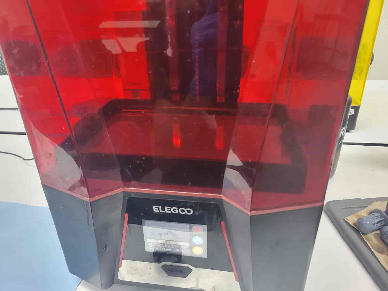
While the second print was much more successful, I did notice a minor raft detachment at around 60% progress. However, the sagging was minimal compared to the first failure, and I allowed the print to complete fully.
Once the print finished:
- I carefully removed the printed parts from the build plate using a scraper.
- Removed the support structures, although they left noticeable marks that will require post-processing.
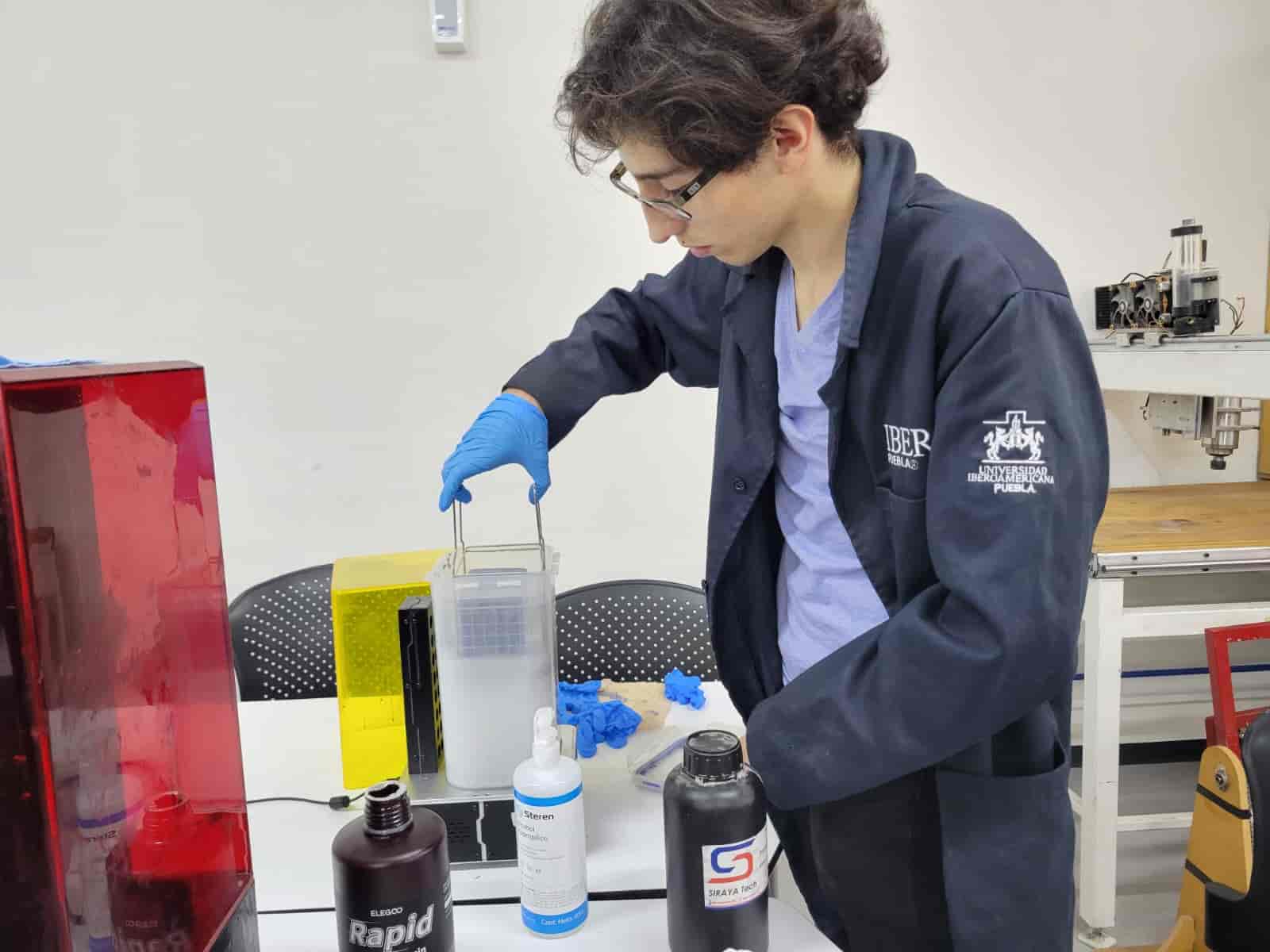
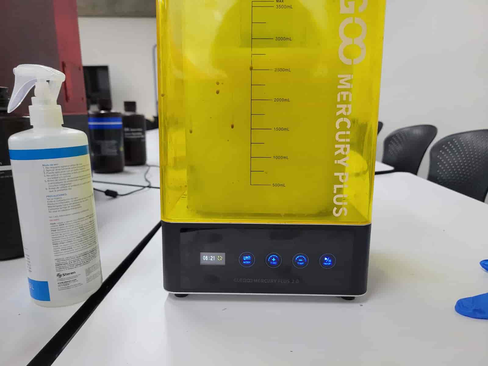
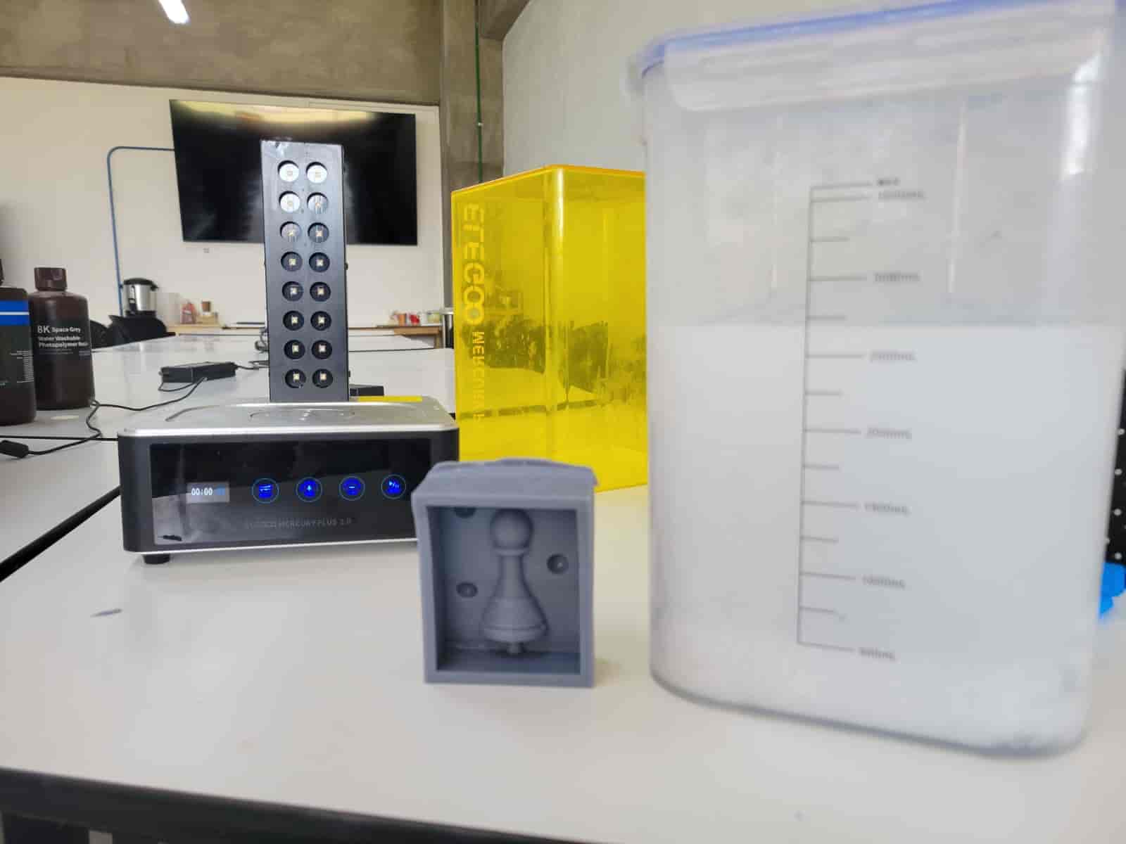
3.4 Post-Processing: Washing and Curing
Post-processing was performed using the Elegoo Mercury 2 washing and curing station:
- The freshly printed parts were immersed in a vat filled with isopropyl alcohol inside the washing unit, where a rotating magnetic stirrer generated a current for effective cleaning.
- After 10 minutes of washing, I removed the parts, dried them thoroughly with paper towels, and prepared them for curing.
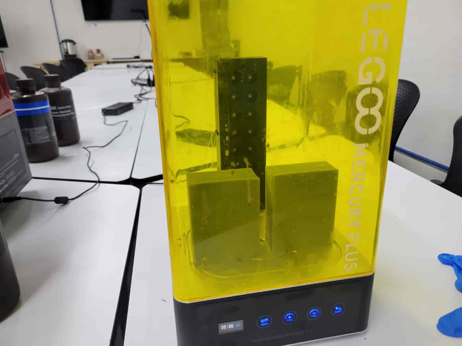
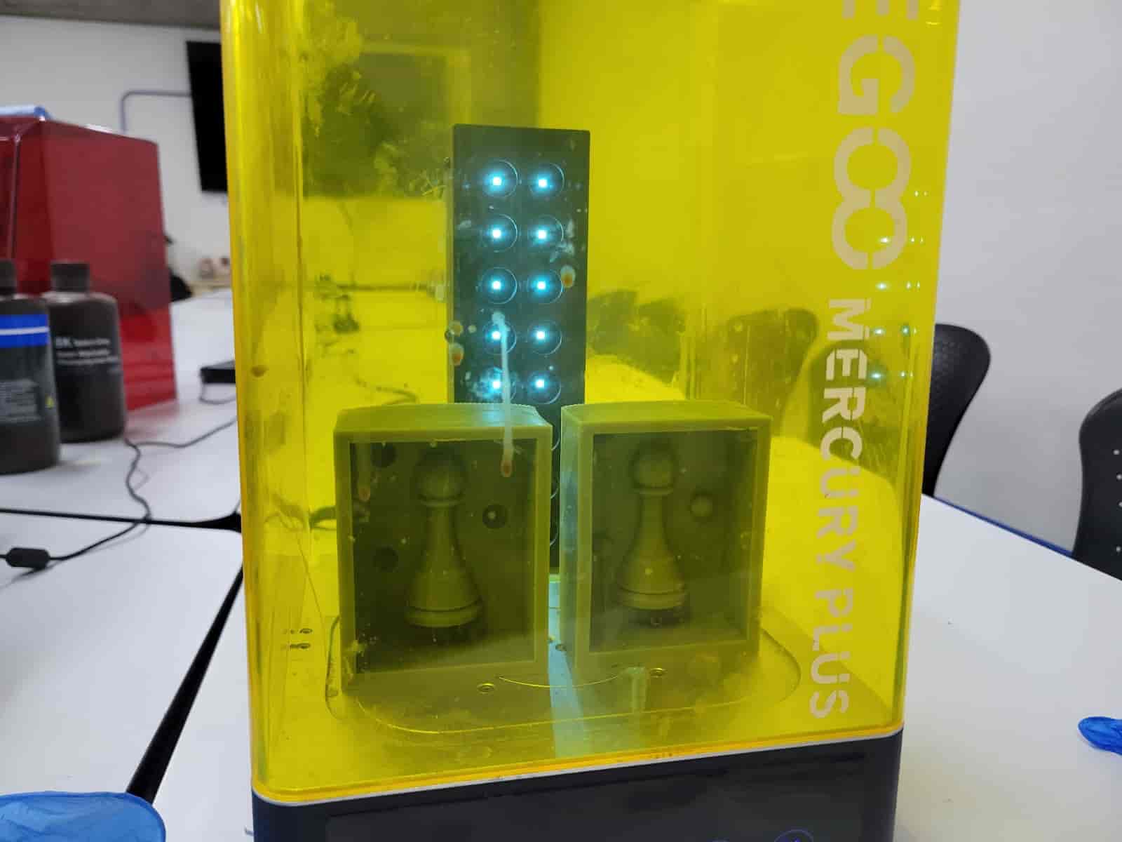
- The parts were placed back inside the Mercury 2 (without the wash vat), and subjected to UV light curing.
- I cured each side for 4 minutes, rotating the parts to ensure even exposure, for a total of approximately 16 minutes per piece.
Interestingly, I also subjected the original failed prints to the same cleaning and curing process. While they remain structurally unusable, curing them ensures they are safely handled and environmentally stable for disposal or archiving as failure examples.
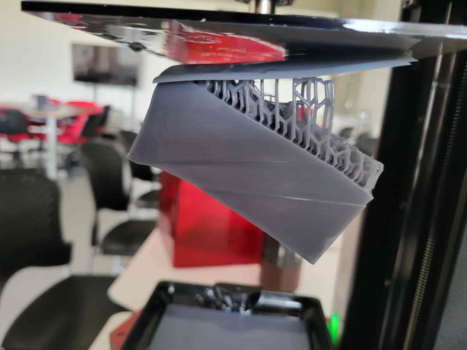
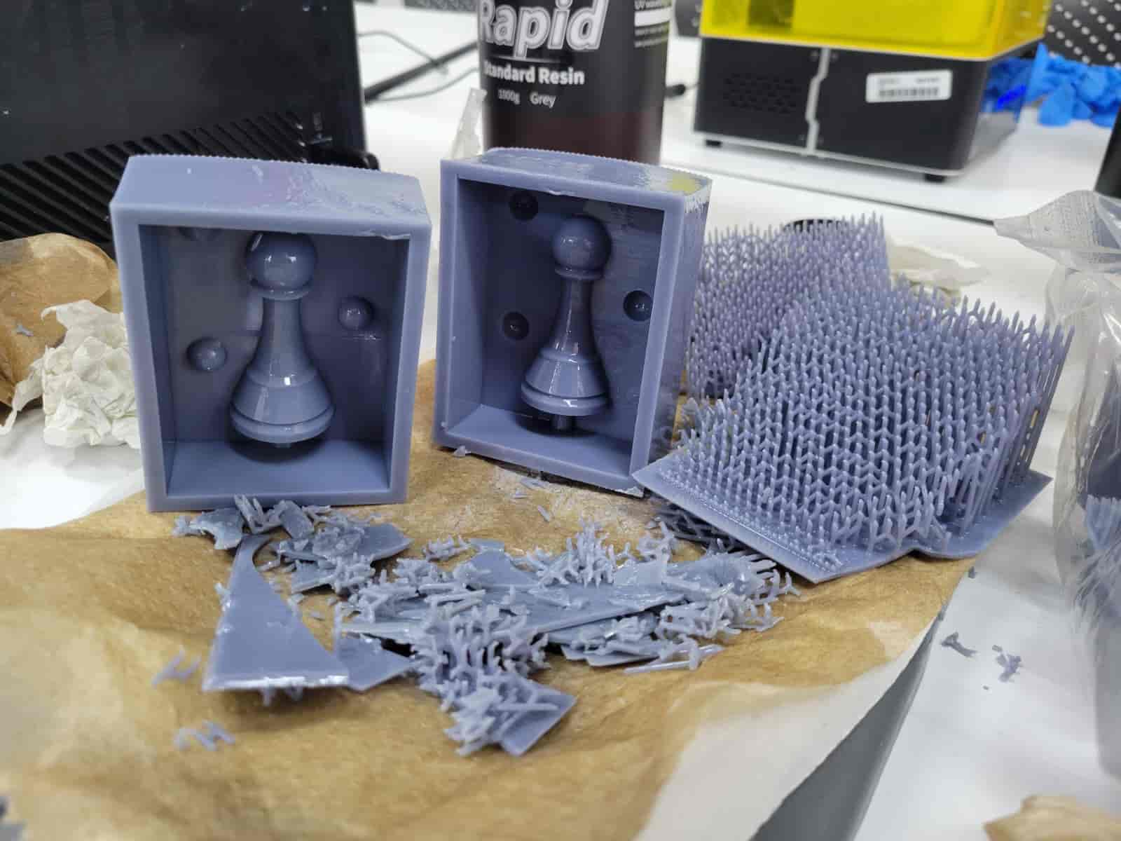
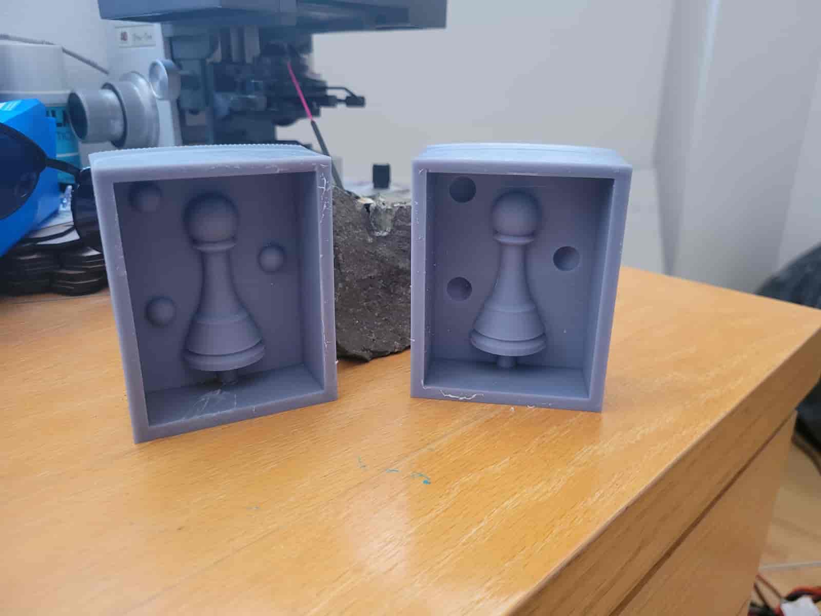
 Here are the results:
4. CNC Wax Milling Mold
4.1 VCarve
Building upon the foundations established during Week 7: Computer-Controlled Machining, we now move beyond flat vector cuts into the carving of a full 3D model.
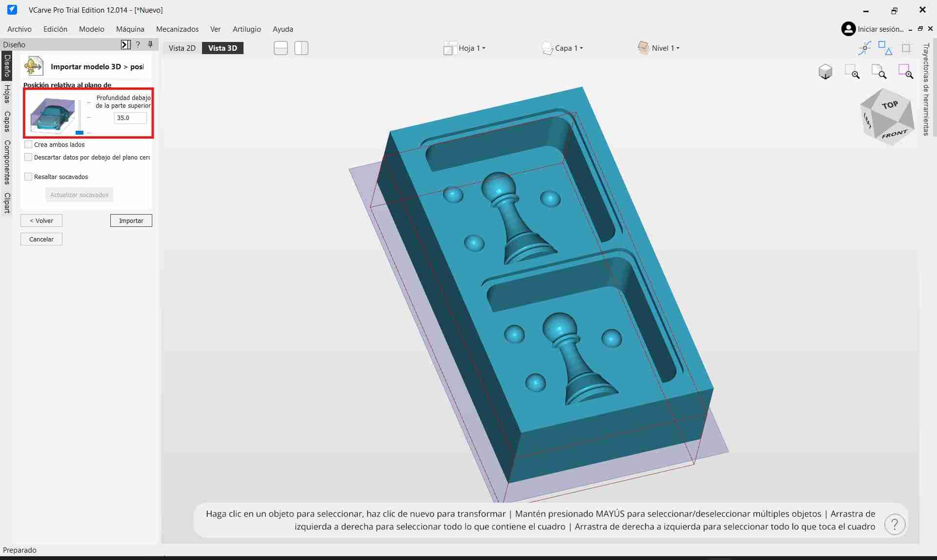
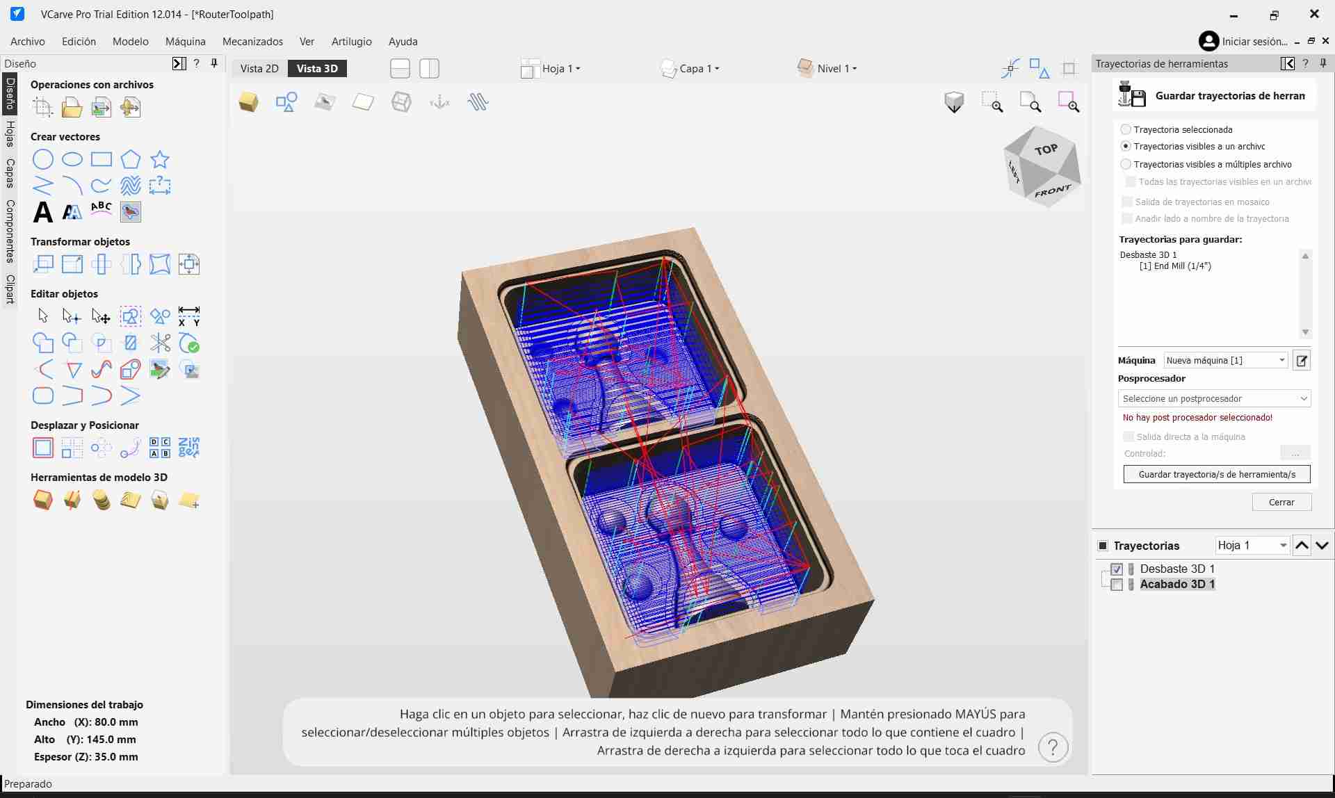
The first step was to configure the workspace dimensions in VCarve. I set the workspace to 80 mm x 145 mm x 35 mm, slightly smaller than our actual wax block to ensure we stayed safely within the available material volume.
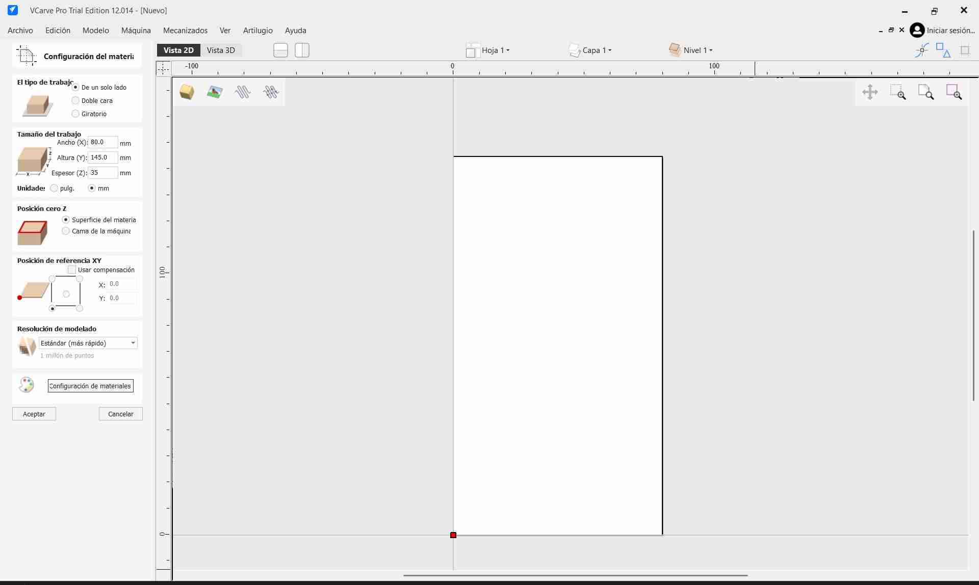
Once the workspace was configured, I imported the STL file of my model. Upon import, I carefully selected the correct orientation, placed the model at the center of the workspace, and ensured it sat entirely above the base plane. This guarantees that all features are properly captured during the generation of the toolpaths.
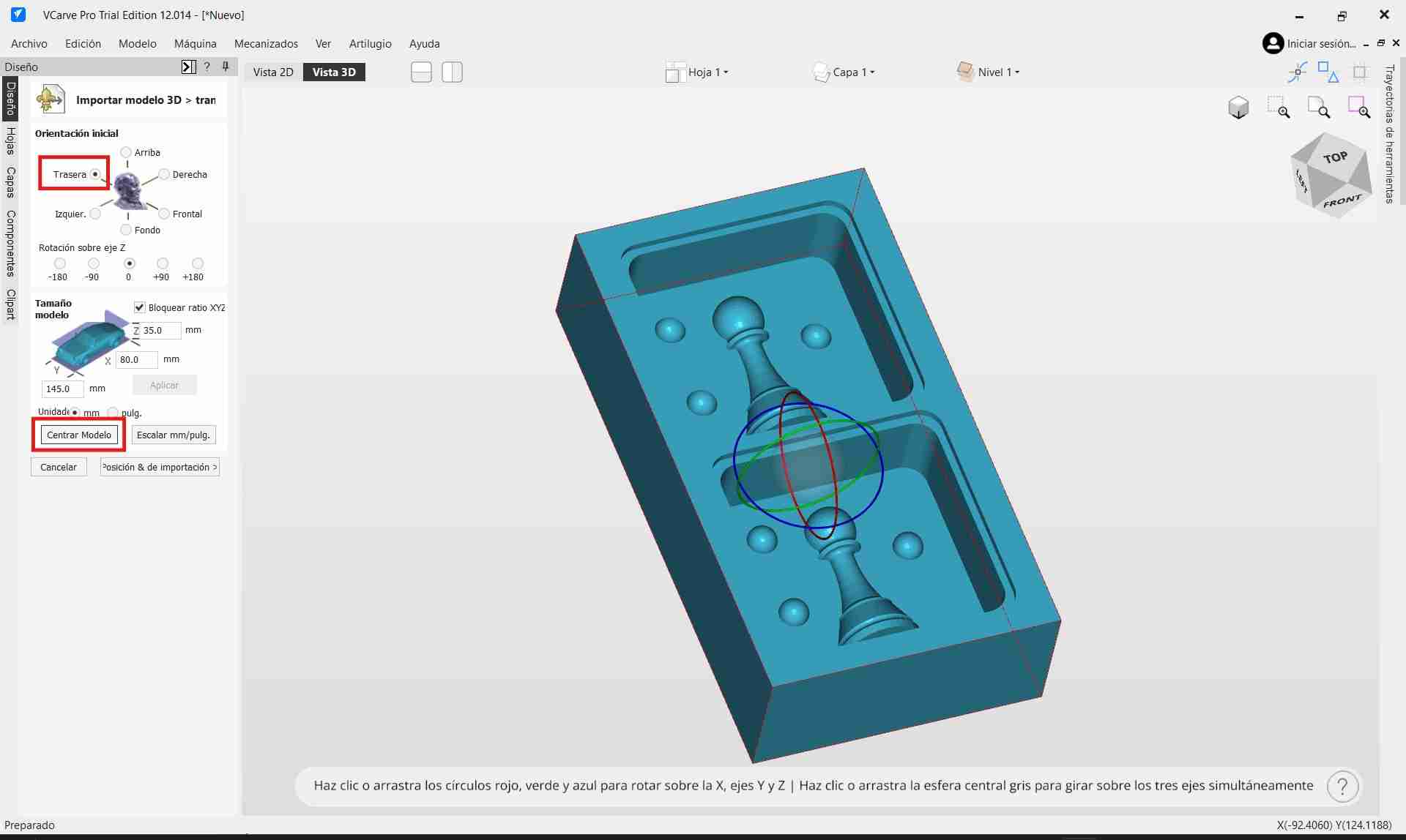
With the model ready, I proceeded to generate the Roughing Toolpath using the options available on the right-hand side menu:
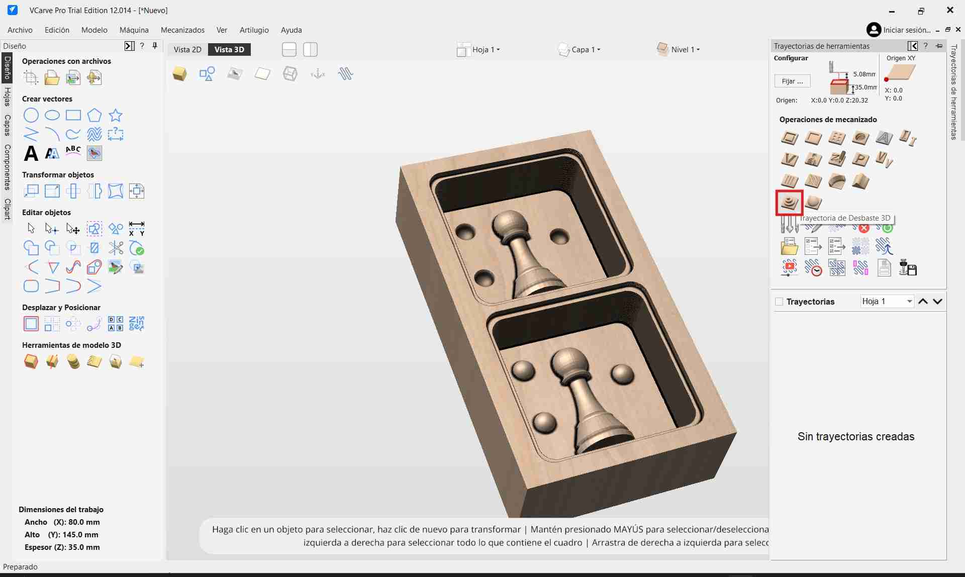
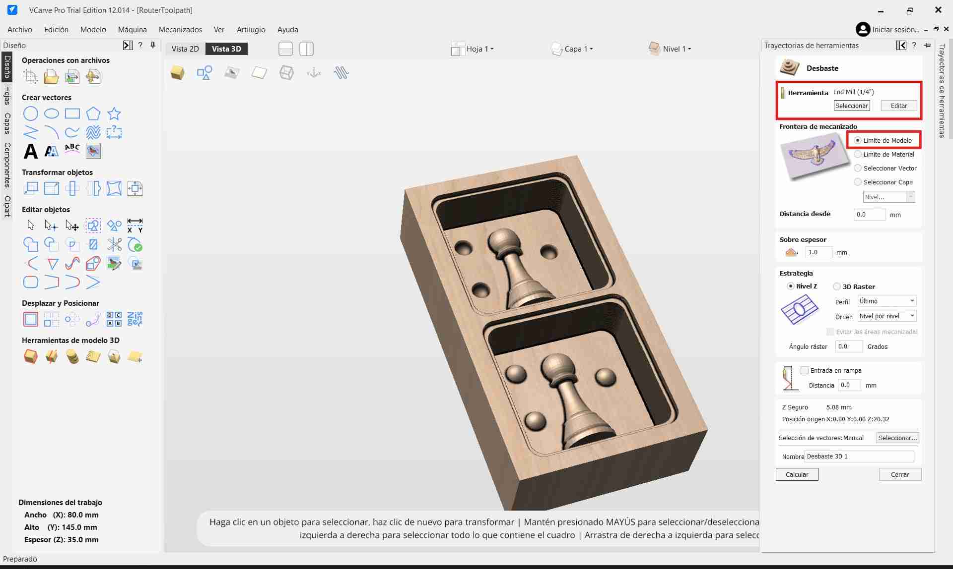
- I configured the toolpath limit to match the 3D model boundaries, allowing VCarve to automatically detect the carving area.
- Other default parameters were left as is, focusing efforts on the correct tool configuration.
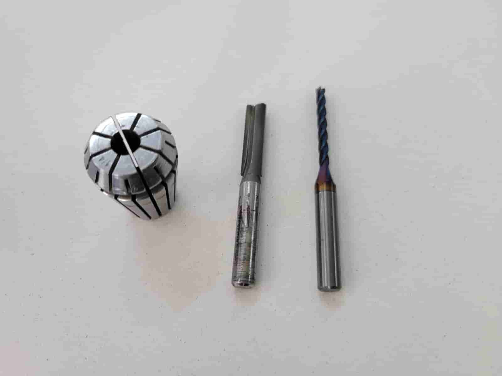
The Tool Setup was one of the most critical steps. Our instructor provided two tools:
- 1/4" 2-flute straight flat endmill with 25 mm flute length for roughing.
- 1/8" 4-flute upcut endmill with 27 mm flute length for finishing.
Since we were roughing first, I configured the 1/4" endmill based on strict rules:
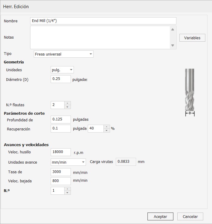
- Tool Diameter and Number of Flutes were correctly entered (0.25" diameter, 2 flutes).
- Depth per Pass was limited to half the tool diameter (approximately 0.125") to ensure safe cutting.
- Stepover was set to 40% of the tool diameter, balancing material removal speed with acceptable surface quality.
The final and most delicate parameters were related to Speed and Feed:
- Spindle Speed -18,000 RPM
- Feed Rate -3000 mm/min
- Plunge Rate -800 mm/min
These values were chosen to respect the material properties of the Ferris® Machinable Wax and to ensure appropriate chip load, preventing tool damage and achieving a clean, controlled machining process.
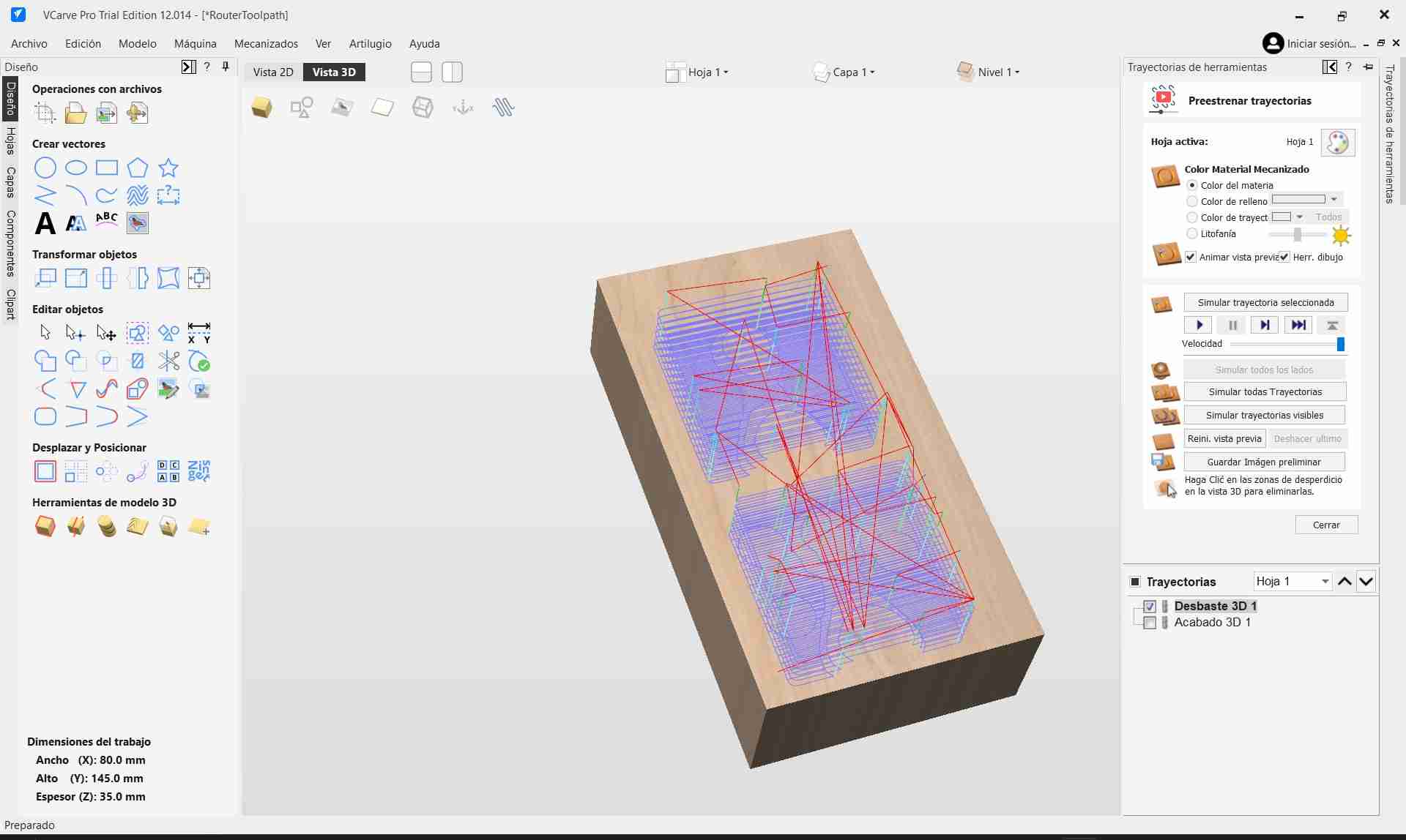
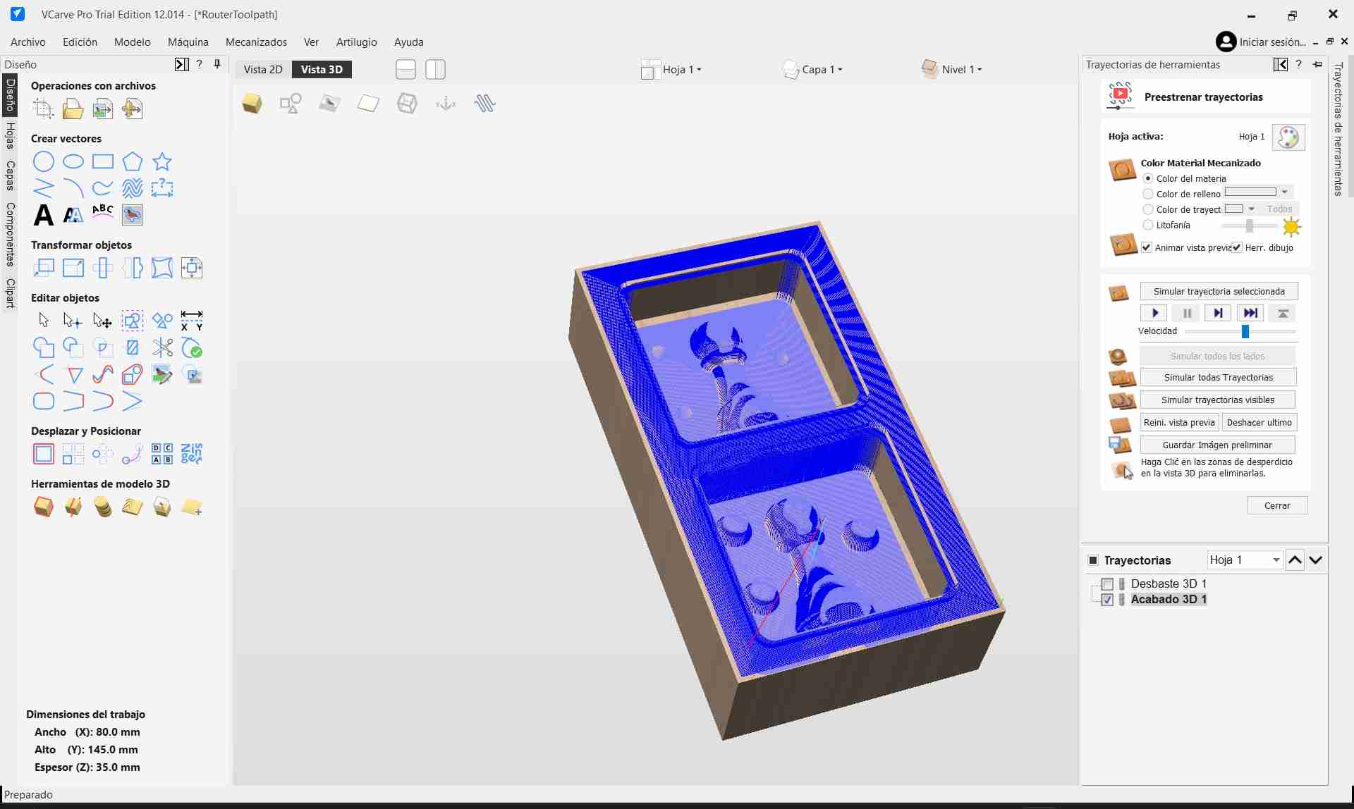
Once all tool parameters were correctly configured, I calculated the roughing toolpath and performed a simulation to verify tool behavior, material removal, and overall job safety.
After completing the roughing setup, I proceeded to configure the Finishing Toolpath for the wax mold.
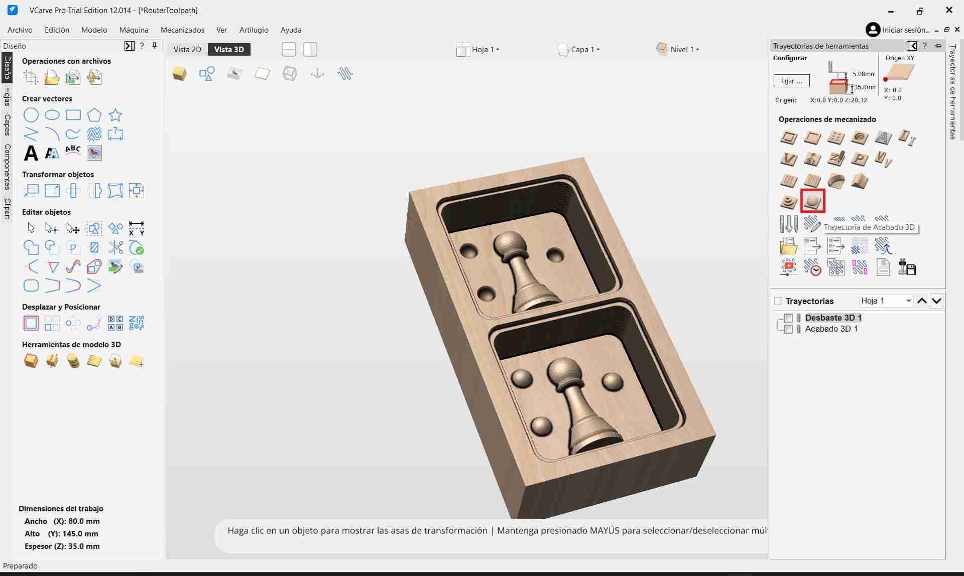
Unlike the roughing pass, the finishing process focuses primarily on precision and surface quality, meaning the default general settings were adequate — only the tool parameters required careful adjustment.
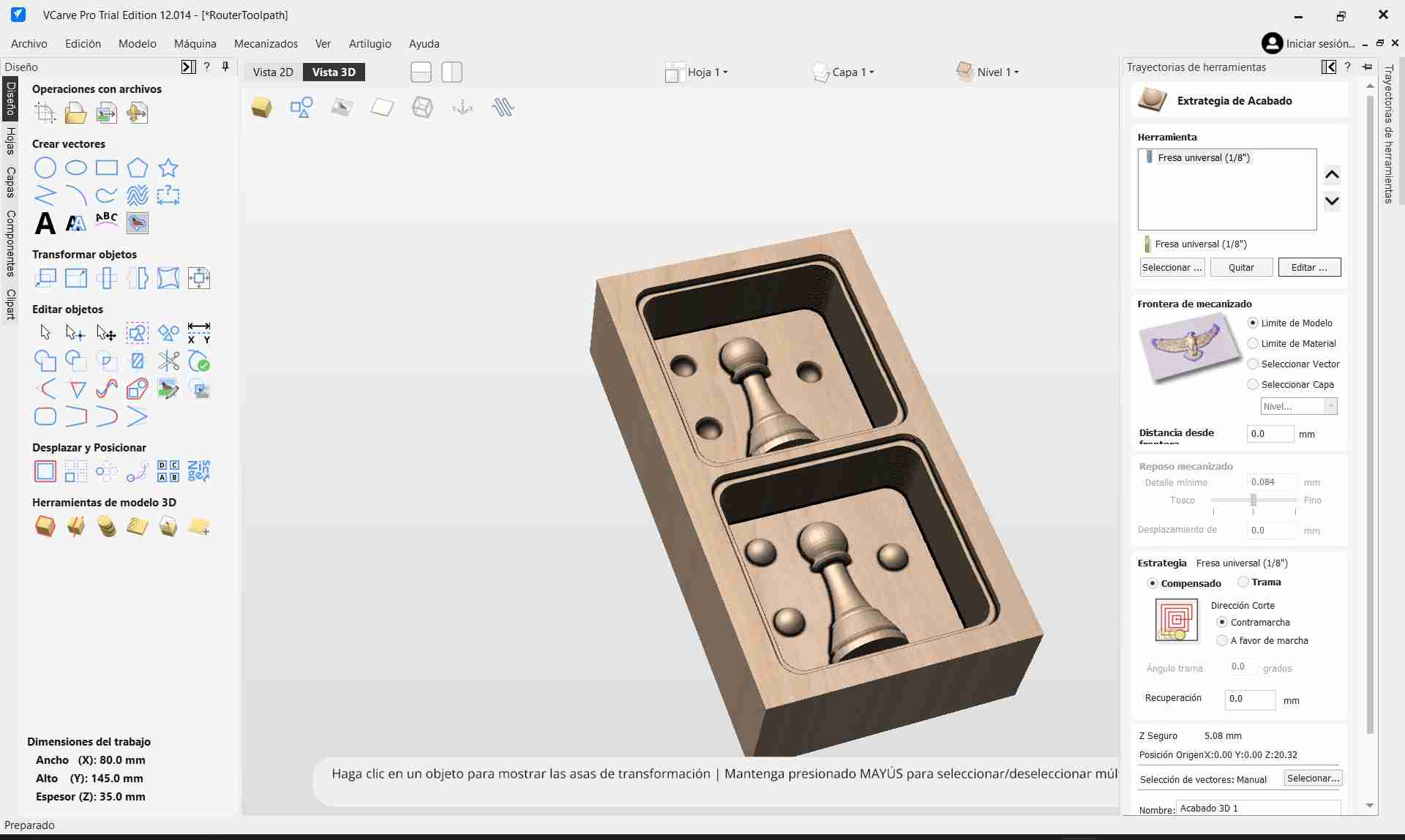
For finishing, I used the provided 1/8" 4-flute upcut endmill, and configured it with the following parameters:
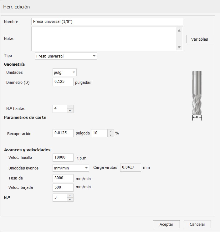
- Tool Diameter - 0.125 inches
- Number of Flutes - 4
- Stepdown Depth - Minimal, letting the software automatically manage depth for delicate final passes
- Stepover - 10% of the tool diameter (extremely fine to achieve a smooth surface finish)
- Spindle Speed - 18,000 RPM
- Feed Rate - 3000 mm/min
- Plunge Rate - 500 mm/min
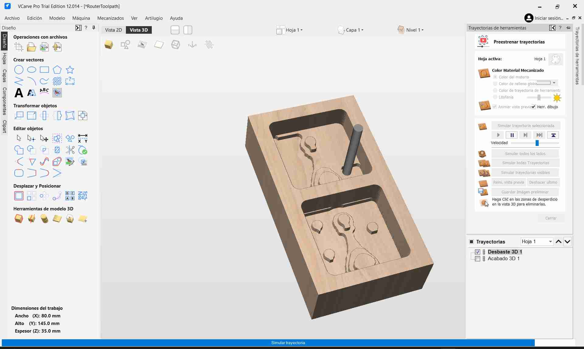
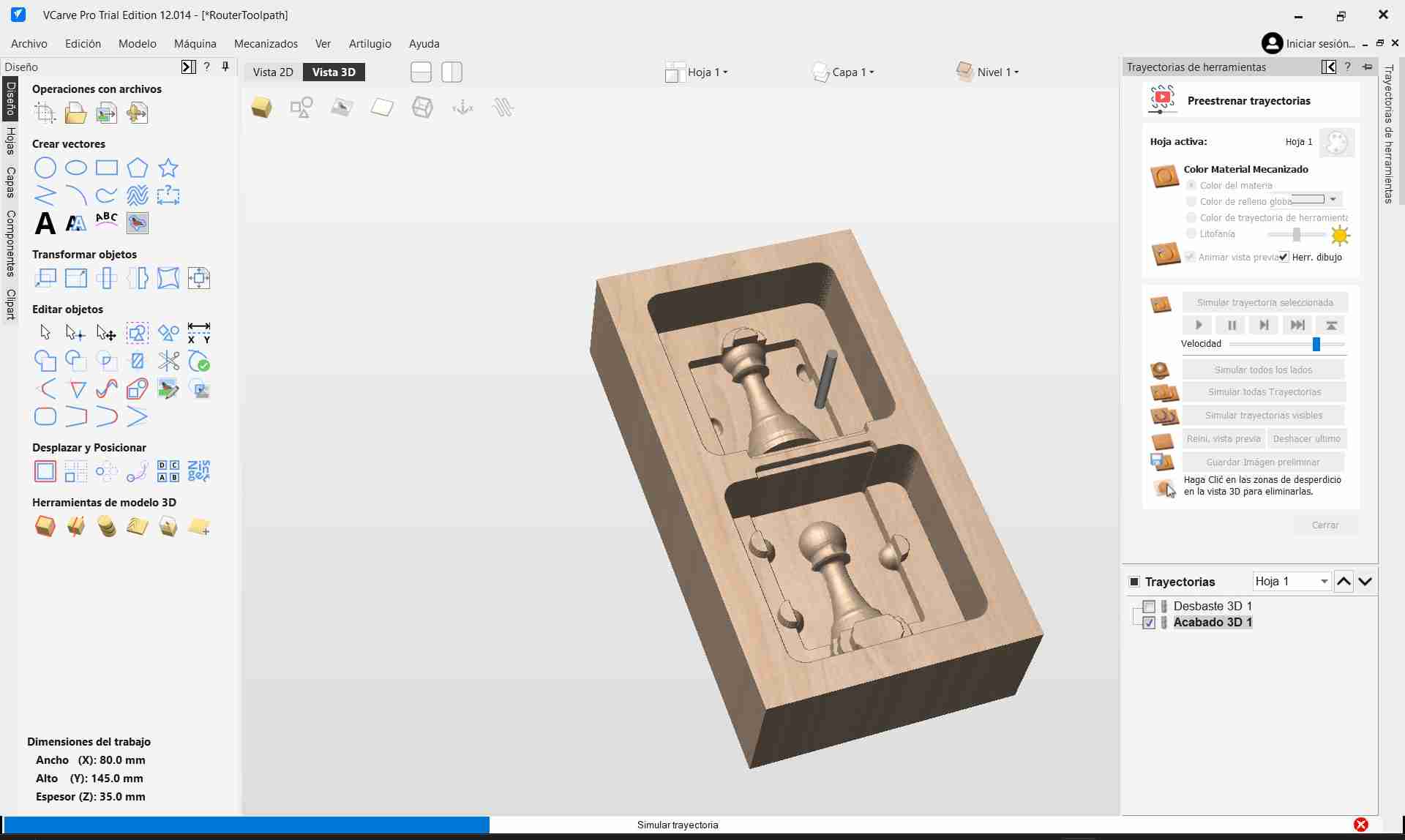
With the tool correctly set up, I simulated both the roughing and finishing toolpaths. The simulation confirmed proper material removal without collisions or excessive tool engagement.
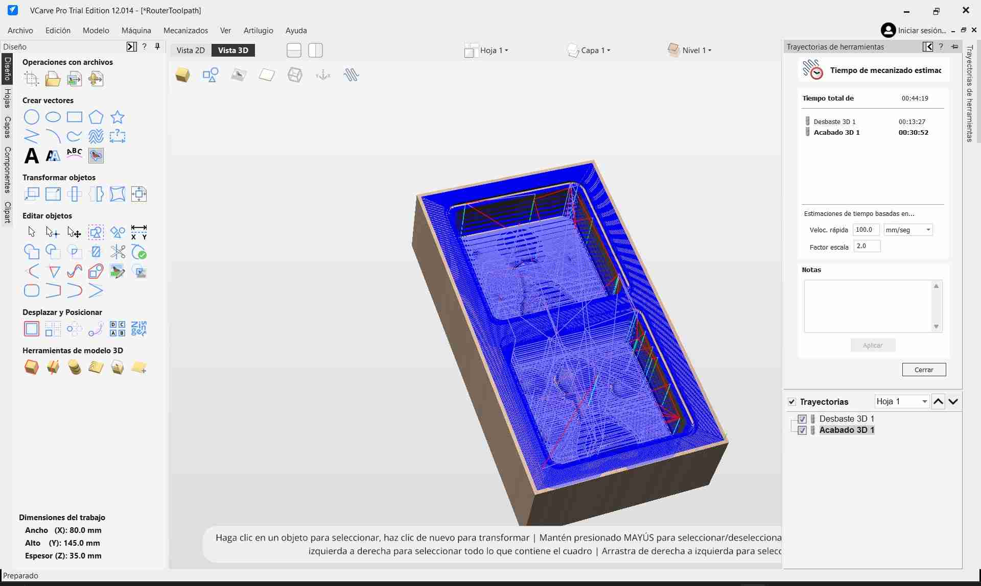
Satisfied with the virtual results, I saved the VCarve project onto a thumb drive. Since my personal computer does not have the necessary post-processor installed, I transferred the file to a computer equipped with the AsiaRobotica-NK105.3-arcs (*.nc) post-processor.
There, I exported the final machine code files (.nc format) required for the CNC router, completing the CAM preparation stage and getting everything ready for the physical milling process.
4.2 Machining Process
To carry out the wax mold machining, I used the AsiaRobotica CNC router with two different tools: a 1/4" 2-flute straight endmill for roughing and a 1/8" 4-flute upcut endmill for finishing. The process began by setting up the machine with the roughing tool.
Tool installation was performed using a collet chuck, which securely holds the bit and is fastened to the spindle using a nut. For the roughing operation, I used a 1/4" collet matching the tool's diameter.
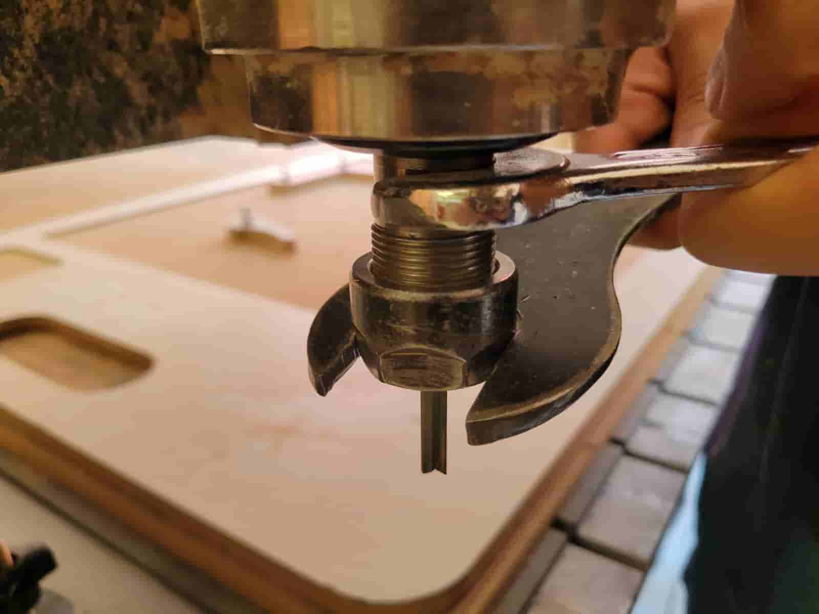
Next, I secured the machining wax block to the machine bed. This was achieved by placing the wax on a sacrificial board equipped with pre-drilled screw holes for clamping assemblies. In addition to using metal clamps to fix the board itself, I applied double-sided tape between the wax and the board to ensure a tight grip.
With the material in place, I proceeded to set the machine's zero points. These were established at the corner of the wax block, aligning the tool's center with the block's edges. The Z-axis zero was set by slowly lowering the spindle while manually rotating the bit until it just scratched the wax surface.
At this point, I noticed a small chip at the tip of one of the flutes on the roughing tool. Concerned, I consulted my local instructor. Since this tool was the only one with the necessary 25 mm flute length, we decided to proceed, but with caution — reducing the feed rate to 70% of the calculated value to reduce stress on the tool.
I uploaded the roughing toolpath to the machine, raised the toolhead to a safe height, and began the machining process. The roughing stage completed successfully, clearing the bulk of the material.
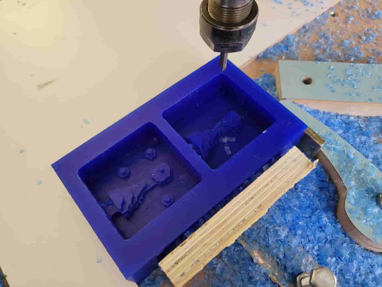
Afterward, I swapped in the 1/8" upcut endmill and re-zeroed the Z-axis. With the finishing file loaded, I initiated the final toolpath. While the operation completed without issue, the finish quality left something to be desired, as visible tool marks remained on the surface.
This was likely due to the use of a flat endmill instead of a ball nose bit, and a relatively high stepover of 10%. A ball endmill and reduced stepover could have significantly improved the finish.
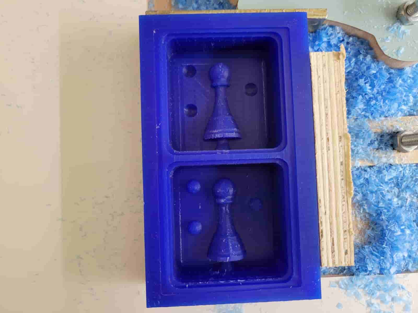
Despite these minor imperfections, the milling process was complete, and I was ready to move on to the silicone casting stage — turning the positive wax mold into a negative silicone mold.
5. Silicone Mold Production
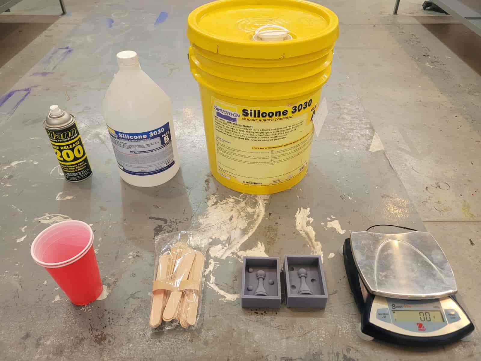
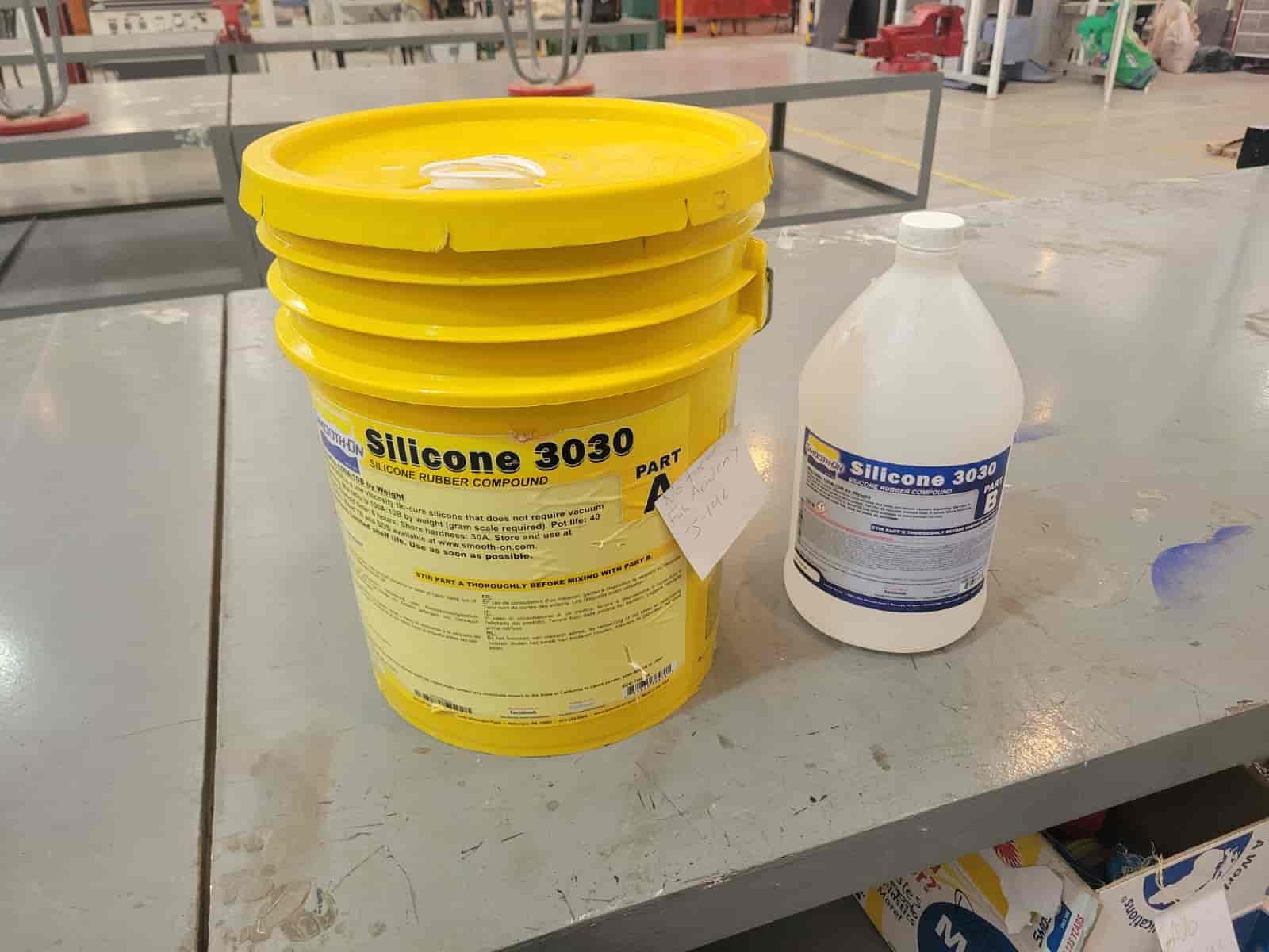
For the production of the negative molds, we used Smooth-On Silicone 3030, a two-part silicone rubber that cures upon the chemical reaction between components A and B. The process is relatively straightforward but requires careful calculation and execution to ensure a proper mold.
Here's the datasheet.
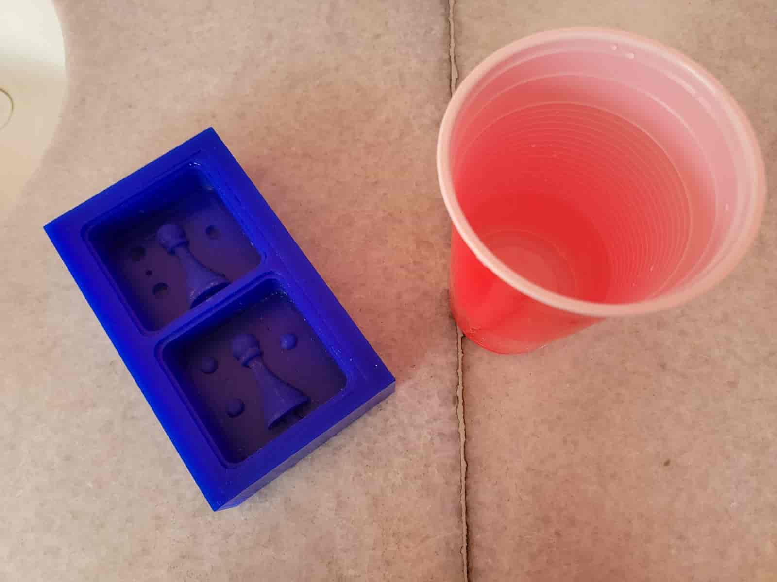
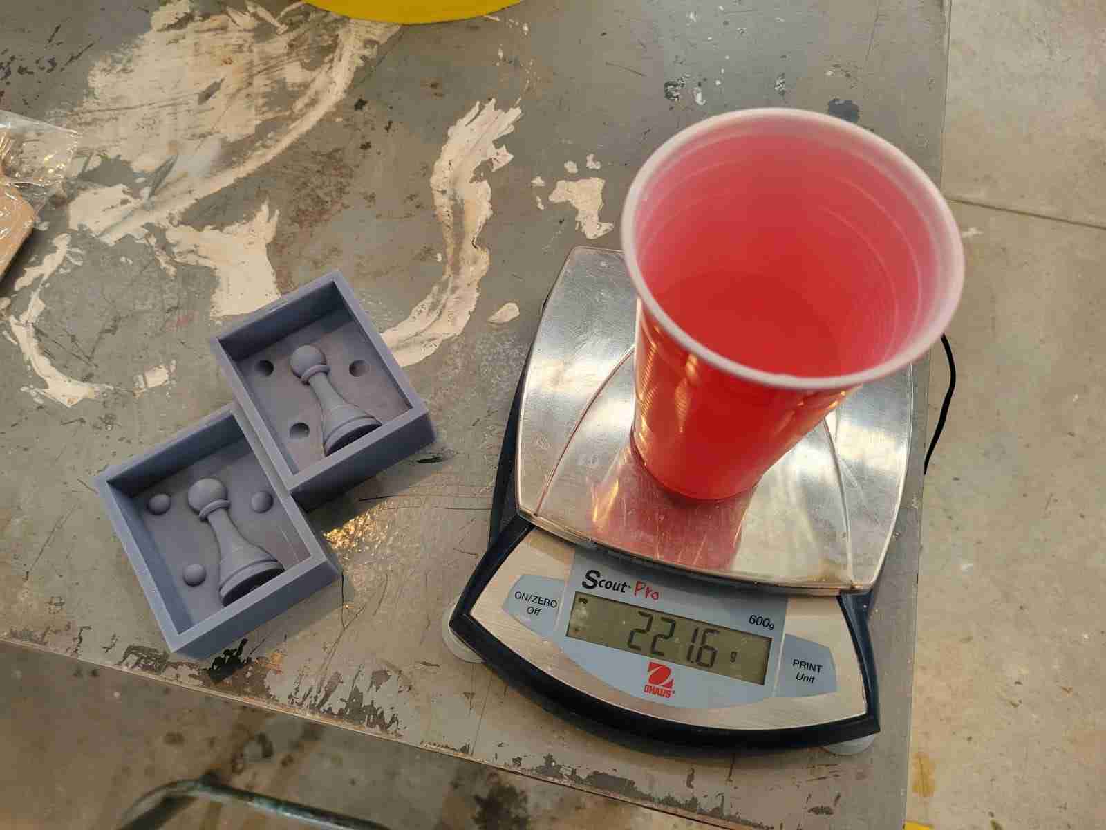
The first step was determining the total volume of silicone needed. We began by measuring the weight of water that each positive mold could hold:
- Wax mold - 144 g of water
- 3D printed molds - 221.6 g of water
Since the specific gravity of Silicone 3030 is approximately 1.18, we calculated the needed silicone weight by multiplying the water weight by 1.18:
- Wax mold: 144 g x 1.18 = 169.92 g
- 3D printed molds: 221.6 g x 1.18 = 261.49 g
To compensate for material loss during the mixing and pouring stages (due to material sticking to the container walls), we added an extra 5% to each value:
- Wax mold final weight: 169.92 g x 1.05 = 178.42 g, rounded to 178 g
- 3D printed molds final weight: 261.49 g x 1.05 = 274.56 g, rounded to 275 g
Since Smooth-On Silicone 3030 uses a 10:1 ratio of Part A to Part B by weight, we divided the total amount by 11 to determine the quantity of Part B:
- Wax mold:
- Part B: 178.42 g ÷ 11 ≈ 16.18 g
- Part A: 178.42 g - 16.22 g = 161.81 g
- 3D printed molds:
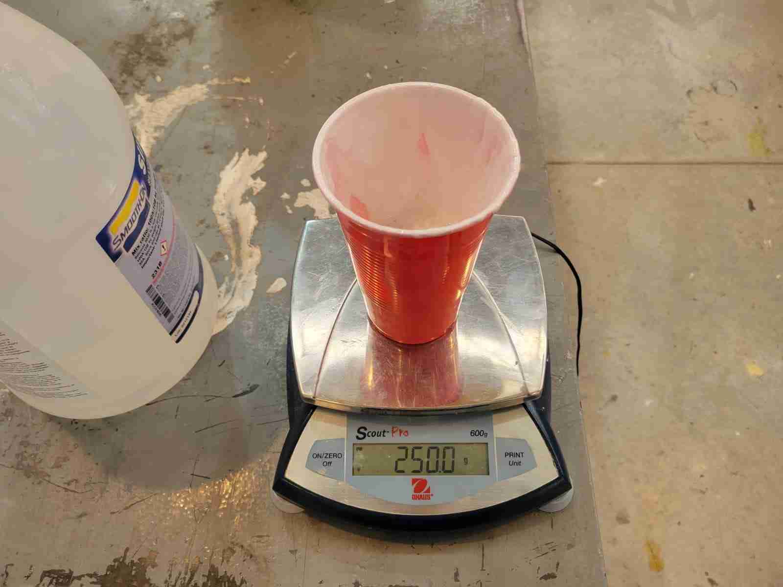
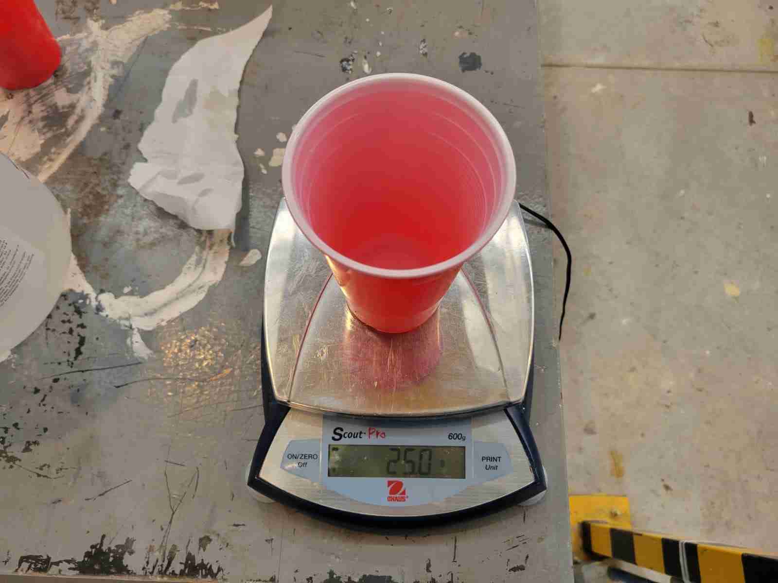
- Part B: 275 g ÷ 11 = 25 g
- Part A: 275 g - 25 g = 250 g
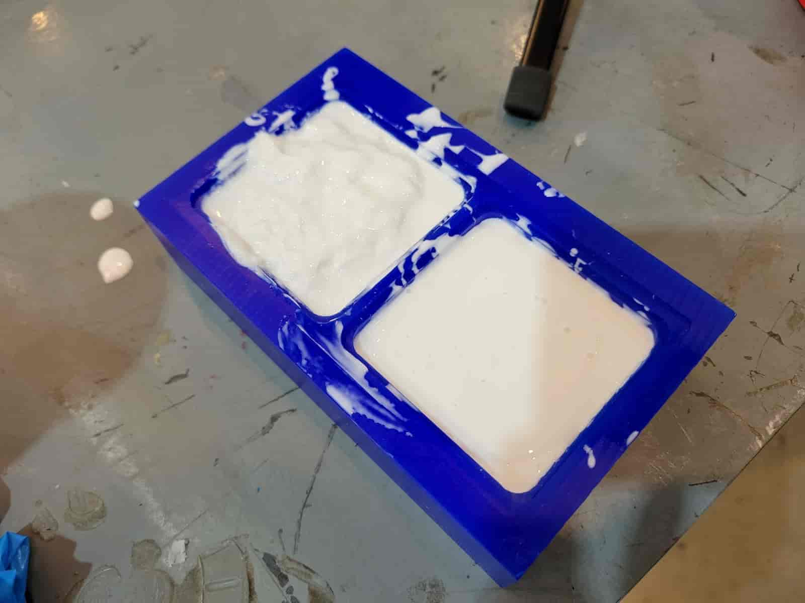
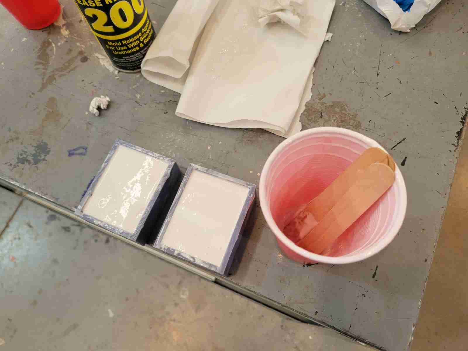
After calculating the amounts, we carefully poured the appropriate weights of each component into separate containers, being extremely precise to respect the 10:1 mixing ratio. We then slowly added Part B into Part A, stirring gently to minimize the introduction of air bubbles.
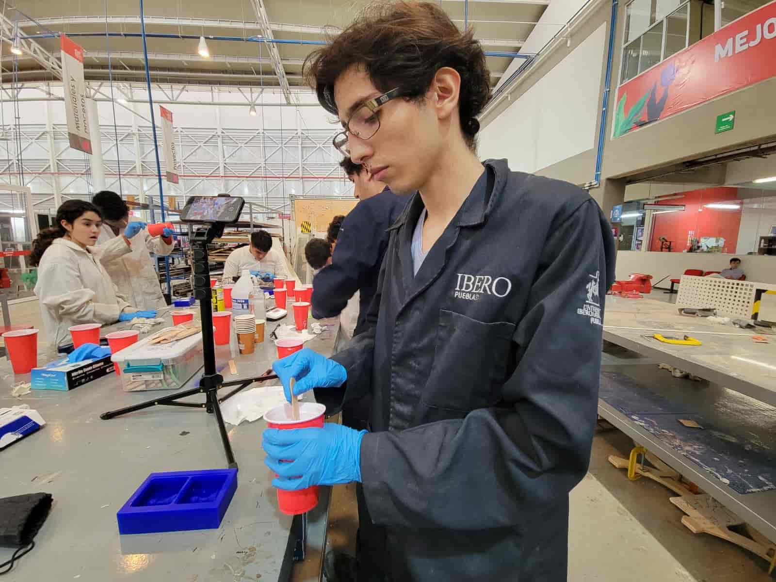
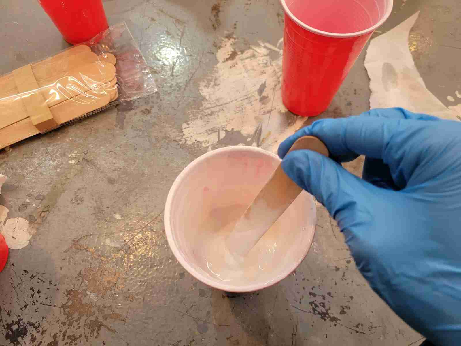
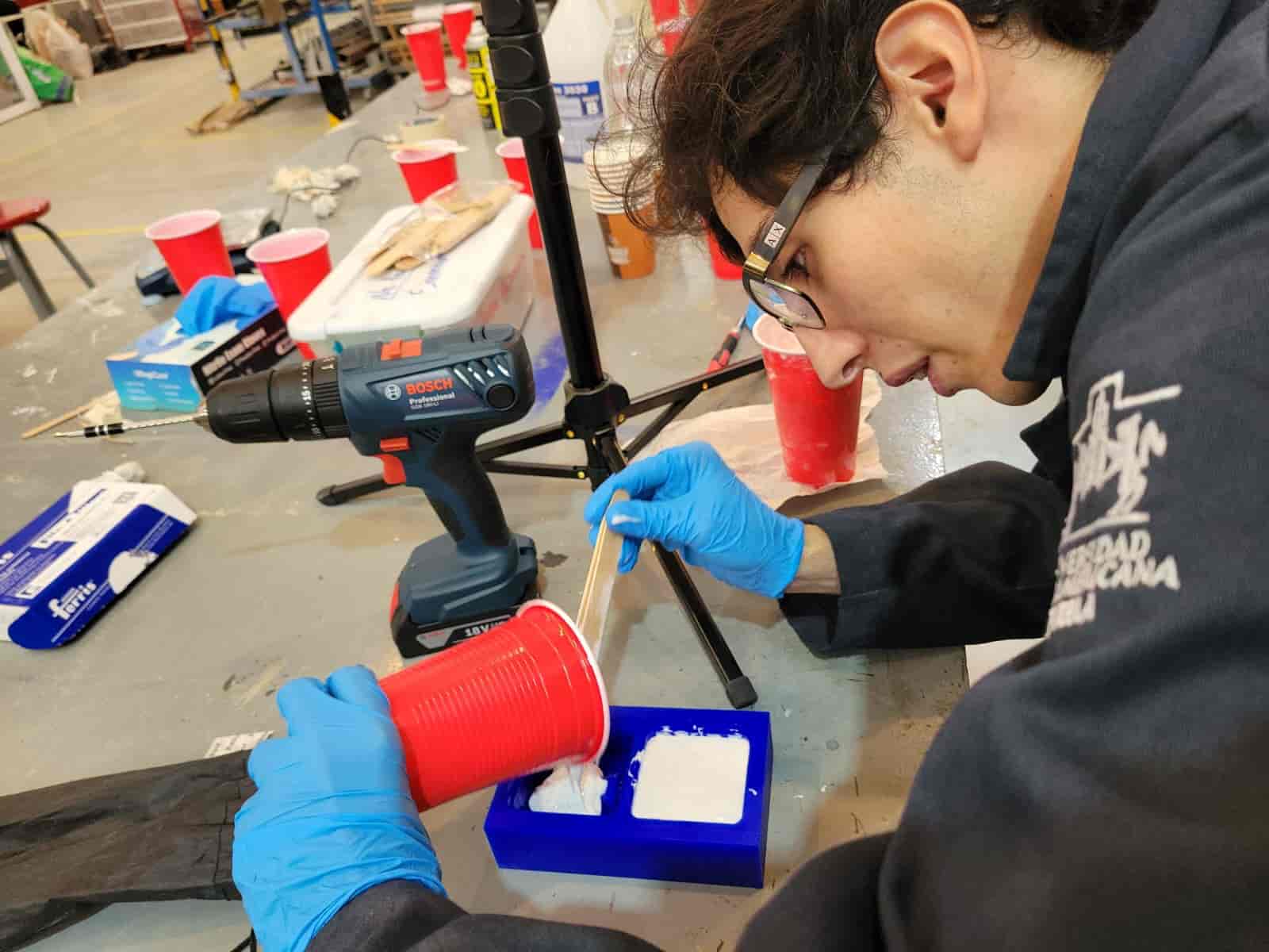
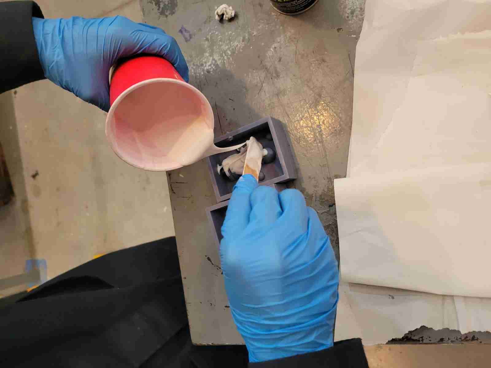
Once the mixture was homogeneous, we poured the silicone into the positive molds (both the 3D printed and milled wax versions). We poured slowly and steadily, aiming to help the silicone flow naturally into all the small details of the geometry and avoid trapping air pockets. Lightly tapping the molds helped release some of the air bubbles; however, using a vacuum chamber would have been a more professional approach to completely eliminate trapped air.
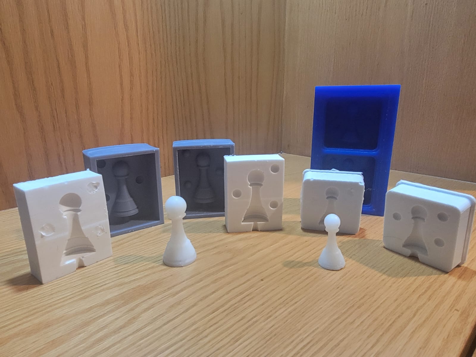
After filling the molds, we let the silicone cure at room temperature for 12 to 16 hours. Although I did not use demolding spray for these molds, it is generally recommended to ease the later removal of the silicone.
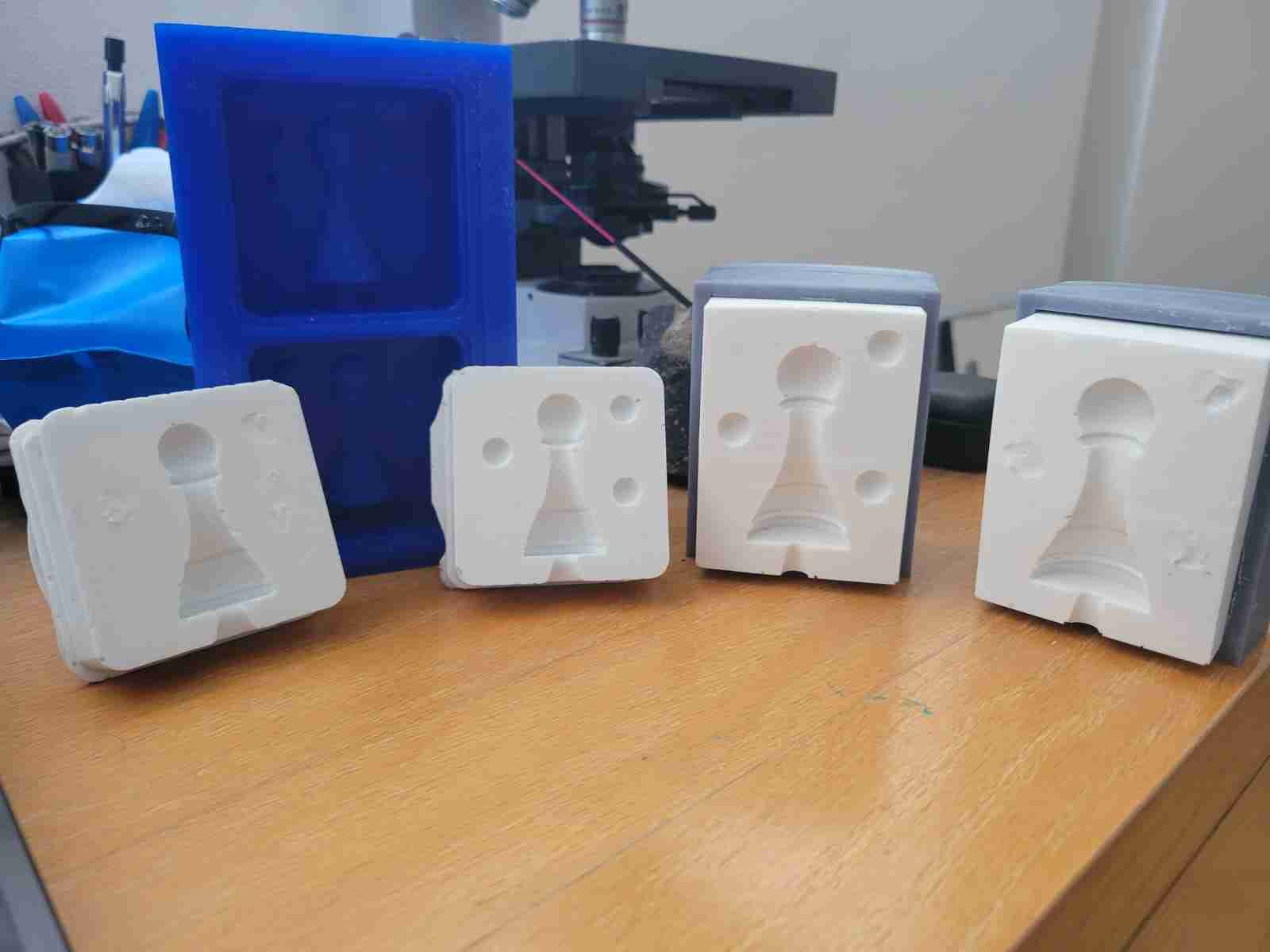
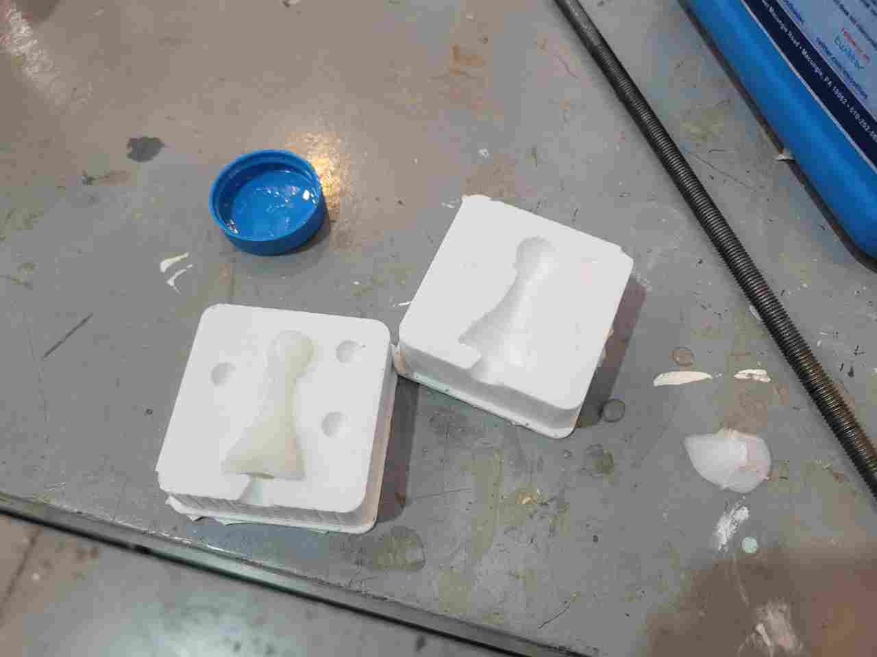
After curing, and removing the failed guiding spheres, I was left with these results:
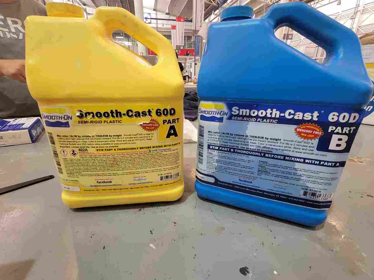
6. Final Part Casting with Smooth-Cast 60D
For the final casting step, we used Smooth-On Smooth-Cast 60D, a semi-rigid plastic that offers excellent durability and a clean finish. The process began with the preparation of both materials and molds.
Here's the datasheet.
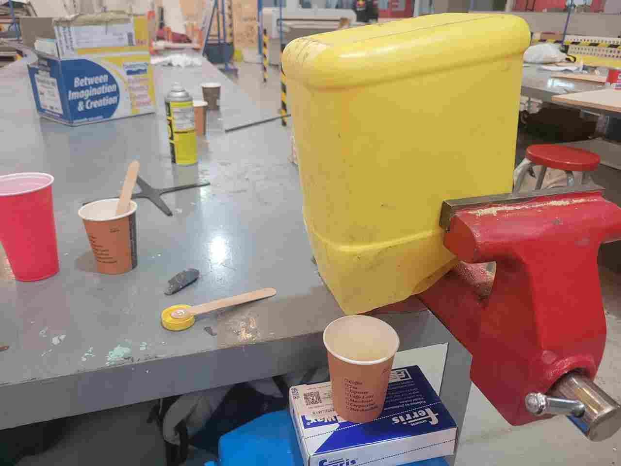
The first challenge encountered was with Component A, which had developed a thick, solidified layer on top. After puncturing this hardened layer, the contents were still difficult to pour. To solve this, I used a vice press to hold the container vertically, allowing the fluid portion to slowly drain into a cup positioned below.
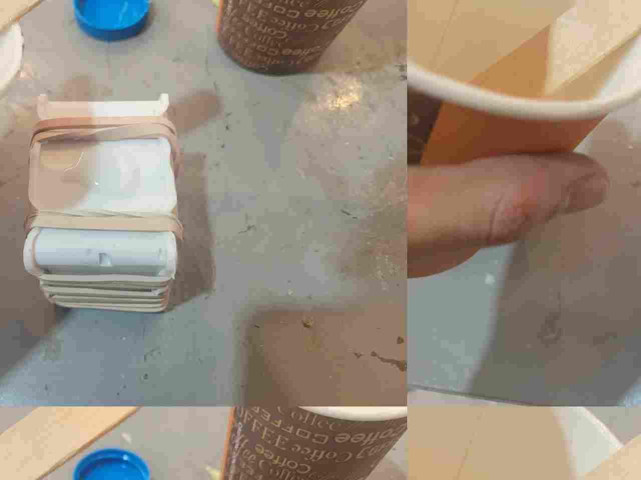
Next, I prepared the silicone molds created in the previous step for casting, by firmly securing the two halves with numerous rubber bands. Special care was taken to keep both halves properly aligned to avoid defects in the final parts.
6.1 Small Pawn Casting
The recommended mixing ratio for Smooth-Cast 60D is 100A:93B by weight. For the small pawn mold:
- Component A: 15.00 g
- Component B: 13.95 g
I poured Component B into the cup containing Component A and gently stirred the mixture for about one minute, making sure to integrate both parts completely while minimizing the introduction of air bubbles. The moment the mixture reached a uniform, more fluid consistency, I slowly poured it into the silicone mold through the inlet cone.
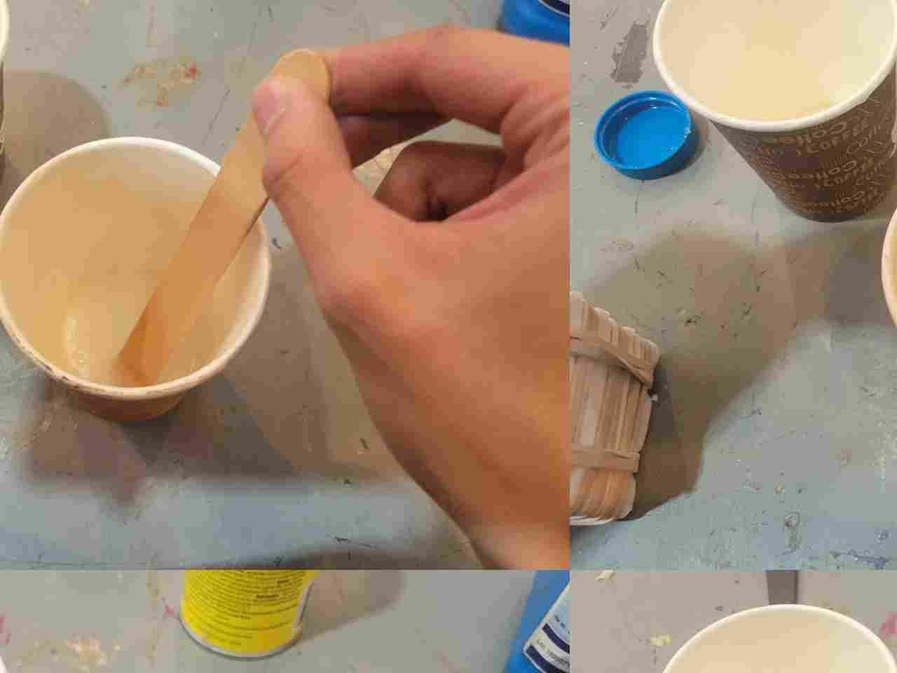
To eliminate any trapped air, I lightly tapped and shook the mold. This helps encourage bubbles to rise to the top and escape the final part.
6.2 Large Pawn Casting
The process was repeated for the larger mold using slightly greater quantities:
- Component A: 20.00 g
- Component B: 18.80 g
Just like before, the mixture was stirred for one minute and poured into the mold slowly and carefully. Once again, I tapped the mold to dislodge any potential air pockets.
The chemical reaction that causes Smooth-Cast 60D to cure is exothermic, which means it releases heat. This change was noticeable approximately two minutes after mixing, as the molds began to warm up.
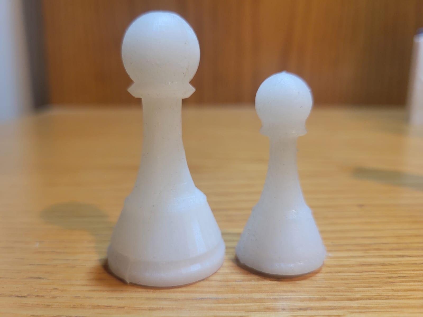
The parts were allowed to cure for about 30 minutes. After that, the rubber bands were removed, and the final pieces were carefully extracted from the molds. The result was a solid, cleanly finished replica of the original model.
HERO SHOTS
7. Comments and Recommendations
Throughout the process of molding and casting, several important lessons and insights emerged that may serve future students well in avoiding common pitfalls and improving results.
7.1 Guide Geometry Orientation
A critical oversight occurred during the design of the guide spheres intended to align both halves of the mold. While one side featured extruding spheres and the other side matching holes, they were not properly mirrored during the modeling stage. As a result, the spheres did not align with the intended sockets, rendering the guide system nonfunctional. The workaround was to remove the spheres entirely and rely on external supports (rubber bands) for alignment, but this experience highlights the importance of verifying symmetrical features during CAD design and simulation.
7.2 Router Tool Selection
The milling process was mostly successful, but it revealed the limitations of the available tooling. The 1/4” tool used for roughing had a chipped flute, which could have compromised the finish or caused mechanical failure if pushed too hard. To mitigate this, the feed rate was reduced by 30%, which preserved the tool for the duration of the task but slightly increased machining time.
In addition, the 1/8” flat endmill used for finishing produced visible tool marks on the wax surface. A ball endmill would have resulted in smoother contours, especially for curved surfaces like the pawn's body. For future users, consider sourcing a ball nose bit for finishing passes and using lower stepover values (e.g., 5-8%) for enhanced surface quality.
7.3 Silicone Casting and Air Removal
While casting the silicone molds, I took care to mix slowly and tap the filled molds to release trapped air. However, this manual method is limited in effectiveness. Some small bubbles were still present in fine details of the mold. The optimal solution would be to use a vacuum degassing chamber after pouring it into the mold. This would eliminate air bubbles before they can become permanent features in the final mold, significantly improving casting fidelity and reducing the likelihood of surface defects.
These observations, while stemming from setbacks, were valuable learning experiences and informed the refinement of techniques for future work.
8. Learning Outcomes
This week offered a comprehensive exploration into the world of molding and casting, merging digital fabrication with traditional manufacturing principles. I gained valuable hands-on experience across the entire workflow: from 3D modeling of both positive and negative molds, to the preparation and production of molds using both resin 3D printing and wax CNC milling, and finally, to casting final parts using silicone rubber molds and semi-rigid polyurethane plastic.
Through both successful results and instructive failures, I developed a deeper understanding of design considerations such as part orientation, wall thickness, material shrinkage, and tool accessibility. I also learned about the importance of selecting the appropriate tools and machining parameters, how to calculate material quantities based on density and volume, and the value of careful mixing and air bubble control during casting.
Ultimately, this week highlighted the versatility and accessibility of molding and casting for replicating complex geometries, as well as the interdisciplinary nature of digital fabrication. I now feel confident in applying these techniques to future projects — both for prototyping and small-scale production.
Files
- SolidWorks 3D Printer Pawn, first half
- SolidWorks 3D Printer Pawn, second half
- SolidWorks Wax Block Pawn